Pima Captain 6 Installation guide
- Category
- Touch screen monitors
- Type
- Installation guide

CAPTAIN 6
6-ZONE INTRUDER ALARM SYSTEM
INSTALLATION GUIDE
System ver. 6.XX

Captain 6 Installation Guide
2
Limited Warranty
PIMA Electronic Systems Ltd. does not represent that its Product may not be compromised and/or
circumvented, or that the Product will prevent any death, personal and/or bodily injury and/or damage
to property resulting from burglary, robbery, fire or otherwise, or that the Product will in all cases
provide adequate warning or protection. The User understands that a properly installed and maintained
equipment may only reduce the risk of events such as burglary, robbery, and fire without warning, but
it is not insurance or a guarantee that such will not occur or that there will be no death, personal damage
and/or damage to property as a result.
PIMA Electronic Systems Ltd. shall have no liability for any death, personal and/or bodily injury
and/or damage to property or other loss whether direct, indirect, incidental, consequential or otherwise,
based on a claim that the Product failed to function.
Warning: The user should follow the installation and operation instructions and among other things test
the Product and the whole system at least once a week. For various reasons, including, but not limited
to, changes in environment conditions, electric or electronic disruptions and tampering, the Product
may not perform as expected. The user is advised to take all necessary precautions for his/her safety
and the protection of his/her property.
This document may not be duplicated, circulated, altered, modified, translated, reduced to any form or
otherwise changed, unless PIMA’s prior written consent is granted.
All efforts have been made to ensure that the content of this manual is accurate. Pima retains the right
to modify this manual or any part thereof, from time to time, without serving any prior notice of such
modification.
Please read this manual in its entirety before attempting to program or operate your system. Should
you misunderstand any part of this manual, please contact the supplier or Technician of this system.
Copyright 2012 by PIMA Electronic Systems LTD. All rights reserved. E&OE
Default system codes:
Master: 5555
Technician: 1234

Captain 6 Installation Guide
3
Table of Contents
1. INTRODUCTION ............................................................................................... 5
1.1 Safety Instructions ................................................................................................................ 5
1.2 Version 6.10 updates ............................................................................................................ 5
1.3 Power consumption ............................................................................................................... 6
1.4 Signs in this guide ................................................................................................................. 6
1.5 Main features ....................................................................................................................... 6
1.6 The LCD Keypad ................................................................................................................... 7
1.7 The Control panel ................................................................................................................. 7
1.7.1 Current limit thermal fuses ................................................................................................. 8
1.8 Battery jump-start................................................................................................................. 9
2. CONNECTING AND WIRING ........................................................................... 10
2.1 The system’s BUS ............................................................................................................... 11
2.2 Z1-Z6 zones and power ....................................................................................................... 11
2.2.1 Common zone wiring ....................................................................................................... 11
2.2.2 EOL resistor loops ............................................................................................................ 11
2.3 SMOKE output .................................................................................................................... 11
2.4 PGM output ........................................................................................................................ 11
2.5 SIREN output ..................................................................................................................... 11
2.6 KEYPAD ............................................................................................................................. 12
2.7 AUDIO ............................................................................................................................... 12
2.7.1 MIC-200 ......................................................................................................................... 12
2.7.2 VU-20(U) ........................................................................................................................ 13
2.7.3 Connecting the GSM-200 .................................................................................................. 14
2.7.4 TELEPHONE .................................................................................................................... 15
2.8 TRANSMITTER .................................................................................................................... 15
2.9 JP3: EOL resistor jumper ..................................................................................................... 16
2.10 AC ..................................................................................................................................... 16
2.11 BATTERY ........................................................................................................................... 16
2.12 Zone #6 as key zone ........................................................................................................... 17
3. PROGRAMMING OPTIONS .............................................................................. 17
3.1 Via the PRG-22 ................................................................................................................... 17
3.2 Via the COMAX ................................................................................................................... 18
3.2.1 Locally ............................................................................................................................ 18
3.2.2 Remotely ........................................................................................................................ 18
3.2.3 Via an LCD Keypad .......................................................................................................... 19
3.2.4 Parameters bar................................................................................................................ 19
3.2.5 Default factory codes ....................................................................................................... 19
3.3 Initializing the keypad ......................................................................................................... 20
3.4 Setting date & time ............................................................................................................. 20
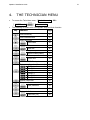
4. THE TECHNICIAN MENU ................................................................................. 21
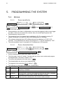
5. PROGRAMMING THE SYSTEM ........................................................................ 22
5.1 Zones ................................................................................................................................ 22
5.1.1 Zone sensitivity ............................................................................................................... 22
5.1.2 Zone characteristics ......................................................................................................... 22
5.1.3 Zone responses ............................................................................................................... 23
5.1.4 Zone name ..................................................................................................................... 23
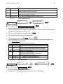
5.2 Monitoring Station communication parameters ....................................................................... 24
5.2.1 PSTN & Radio subscriber IDs, Double Report ...................................................................... 24
5.2.2 Station format, ACK, Kissoff delay ..................................................................................... 24
5.2.3 Automatic communication tests ......................................................................................... 25
5.2.4 GSM-200 cellular module .................................................................................................. 26

Captain 6 Installation Guide
4
5.2.5 Reporting codes .............................................................................................................. 27
5.2.1 Central Monitoring Station telephones, rings ....................................................................... 28
5.3 The SIREN and SMOKE outputs ............................................................................................ 28
5.4 System configuration ........................................................................................................... 29
5.4.1 Config 1 .......................................................................................................................... 29
5.4.2 Config 2 .......................................................................................................................... 29
5.4.3 Config 3 .......................................................................................................................... 30
5.4.4 Config 4 .......................................................................................................................... 30
5.4.5 Config 5 .......................................................................................................................... 31
5.4.6 Config 6 .......................................................................................................................... 32
5.5 System responses ............................................................................................................... 32
5.5.1 PANIC alarm response ..................................................................................................... 32
5.5.2 AC failure response .......................................................................................................... 33
5.5.3 Battery failure response ................................................................................................... 33
5.5.4 Phone line failure response ............................................................................................... 33
5.5.5 Zone fail response ........................................................................................................... 33
5.5.6 The response to arming/disarming by a key switch ............................................................. 34
5.6 The Entry/Exit delay times ................................................................................................... 34
5.6.1 User partitions ................................................................................................................. 34
5.7 The Technician code ........................................................................................................... 35
5.8 Defaulting the system & fast loading ..................................................................................... 35
5.8.1 Defaulting the system ...................................................................................................... 35
5.8.2 Fast parameter loading .................................................................................................... 35
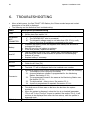
6. TROUBLESHOOTING....................................................................................... 36
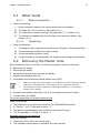
6.1 Other faults ........................................................................................................................ 37
6.1.1 Radio transmitter ............................................................................................................. 37
6.1.2 Telephone ...................................................................................................................... 37
6.2 Retrieving the Master code .................................................................................................. 37
7. PARTITIONS ................................................................................................... 38
7.1 Additional information ......................................................................................................... 38
8. SUPPLEMEN TARY PRODUCT .......................................................................... 39
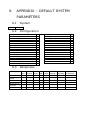
9. APPENDIX – DEFAULT SYSTEM PARAMETERS ............................................... 40
9.1 System .............................................................................................................................. 40
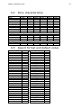
9.2 Configuration...................................................................................................................... 40
9.3 Responses .......................................................................................................................... 40
9.4 Zone characteristics ............................................................................................................ 41
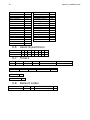
9.5 Report format and default codes .......................................................................................... 41
9.6 Users & partitions ............................................................................................................... 42
9.7 Timers ............................................................................................................................... 42
9.8 Default codes ..................................................................................................................... 42
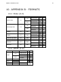
10. APPENDIX B - FORMATS ................................................................................ 43
10.1 Pulse (4-2) ......................................................................................................................... 43
10.2 DTMF (4-2) ........................................................................................................................ 43
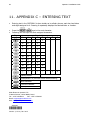
11. APPENDIX C – ENTERING TEXT ..................................................................... 44

Captain 6 Installation Guide
5
1. INTRODUCTION
This guide provides the installation, wiring and programming instructions for PIMA’s CAPTAIN
6 intruder alarm system.
The CAPTAIN 6 has many features that fits customer’s individual needs, and yet it remains
easy to install and simple to program and use, both by the end-user and the Technician.
CAPTAIN 6 is secured against Radio-Frequency (RF) and Electro-Magnetic Interferences (EMI).
Information on programming user codes and other end user parameters can be found in the
CAPTAIN 6 User Guide.
1.1 Safety Instructions
Your CAPTAIN 6 Alarm System has been registered in accordance with EN60950 and its rules.
EN 60950 requires us to advise you the following information:
1. In this alarm system hazards of fire and electric shock exist. To reduce the risk of fire or
electric shock, do not expose this alarm system to rain or moisture. Pay attention:
Telephone cords could be a good conductor for lightings energy.
2. Do not open the door of the alarm system. Dangerous high voltages are present inside of
the enclosure. Refer servicing to qualified personnel only.
3. This alarm system should be used with AC 230V/110V, 50/60Hz, protected by anti-
electric shock breaker. To prevent electric shocks and fire hazards, do NOT use any
other power source.
4. Do not spill liquid of any kind onto the unit. If liquid is accidentally spilled onto the unit,
immediately consult a qualified service.
5. Install this product in a protected location where no one can trip over any line or power cord.
Protect cords from damage or abrasion.
6. Disconnect all sources of power supply before proceeding with the installation.
7. Do not install low voltage wires near AC power wires; they should be separated.
8. Use only standard AC transformer.
9. Connect the AC transformer output to the terminal block on the control panel as marked.
10. Connect the AC line cord to the terminals as marked (GND; N; L).
1.2 Version 6.10 updates
Added feature: battery jump-start. See section 1.8.
New PCB version C with the following major changes:
1. The siren type jumpers have been cancelled.
2. A new EGND (earth ground) terminal for connecting grounding was added.
3. The AC & battery terminals are now detachable.

Captain 6 Installation Guide
6
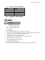
1.3 Power consumption
Module
Details
LCD keypad
12VDC 20mA rms
LCD keypad illuminating
12VDC 110mA rms
GSM-200
13.8VDC 250mA rms
MIC-200
12VDC 5mA rms
TRU/TRV
13.8VDC 10mA rms
VU-20N/U
12VDC 45mA rms
RXN-400/410
13.8VDC 15-20mA rms
1.4 Signs in this guide
Warning
Note
Press briefly
Press and hold a key until a
confirmation beep is sounded
1.5 Main features
6 alarm zones
Up to 2 partitions
Up to 4 Monitoring Station telephone numbers and 3 owner’s
Various ways for arming and disarming: keypad, key switch, remote control auto-arming
Keypad types: LCD screen (RXN-400/410), LED (RX-6/406)
2 operating modes: Full and partial (“Home”)
System operations are fully logged, part in a non-volatile memory
Various codes: Master, 8 Users, Short
User Code #8 can serve for Duress alarm
Temporary zone bypassing
“Chime” monitoring mode per zone
Built-in PSTN dialer and optional long-range radio and cellular communication

Captain 6 Installation Guide
7
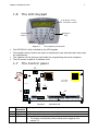
1.6 The LCD Keypad
System
Status
Functions
LCD display, 2 lines,
16 characters in each
Navigation
keys
Diagram 1. LCD keypad keys and screen
The CAPTAIN 6 is fully controlled by the LCD keypads.
The keypads number buttons are used for accessing the user and technician menus and
for programming.
The 4 buttons on the right are used mostly for programming and menu navigation.
The LCD screen is made of 2 character lines.
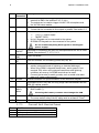
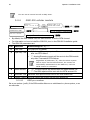
1.7 The Control panel
Diagram 2. CAPTAIN 6 PCB
No.
Terminal/
Connector
Description
1
Z1-Z6
6 inputs for dry contact detectors & (-) terminal
2
(+)/(-)
Power supply for PIR/ultrasonic/etc., detectors
3
SMOKE
Output for resetting Smoke & Fire detectors
The output is temporarily disconnected when triggered. See
section 5.3.
-
AC
BATT
U11
TRANSMITTER
PIMA-6
JP3
F3
+V
KEYPAD
11
15
12
13
14
1 2 3 4 6 7 8 102 5 9
F1
P/N 3610105 Rev. C
Z1Z2Z3Z4Z5Z6
Z O N E S +VSMOKE PGMSRN
OUTPUTS-
1KEYPADOUTLINE
TELEPHONE
SET
-AUDIO
IN
F2
Z7Z8234
+INOUT-EGND
+
-

Captain 6 Installation Guide
8
No.
Terminal/
Connector
Description
4
PGM
Auxiliary output. When triggered, it can be disconnected or
switched to GND. See sections 5.4.3, 5.4.4.1.
The output can be used to trigger the MIC-200 microphone and
the VU-20N voice module.
5
SRN +/-
Siren Output
2 sirens can be connected to this output in parallel. See section 2.5
6
KEYPAD
Terminals for connecting the system BUS. The terminals are:
(+V)/ (-): power supply
IN/OUT: DATA
Up to 6 keypads can be connected to the system
All PIMA LED keypads can be connected to the system
Do not connect anything but keypads to the keypad
power supply!
7
AUDIO (-)
/IN/OUT
Terminals for connecting the MIC-200 microphone and the VU-20 voice
module. See sections 2.7, 2.7.2, 5.1.3.
8
TELEPHONE
LINE
Line-in terminals
9
TELEPHONE
SET
Line-out terminals for connecting phone sets, fax, etc.
10
EGND
Earth Ground terminal. Can be used in areas of severe electrical
activity (abnormal levels of lightning or electrical discharge).
When using PIMA’s integrated transformer, earth ground is not
required. Only when using external transformer and lightning
conditions are severe, the EGND terminal can be used.
Connect the terminal to earth grounds, such as metal cold water
pipe or AC power outlet ground
11
KEYPAD
A Molex connector for quick connection of the technician keypad
12
Transmitter
A connector to the TRV/TRU-100 long range radio transmitters and the
GSM-200 cellular module
13
Backup
Battery
cables
RED cable: (+)
BLACK cable: (-)
Inverting the battery contacts can damage the PCB
14
AC
14-16 VAC Voltage input
The cross-section area of the AC cable must be at least 0.75mm2
15
JP3
EOL resistor loops jumper. See section 2.9
1.7.1 Current limit thermal fuses
Fuse
Details
F1
0.9A, siren power supply
F2
750mA, Keypads and detectors power supply
F3
Battery

Captain 6 Installation Guide
9
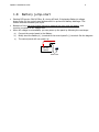
1.8 Battery jump-start
Starting PCB version 3610105 Rev. B., during AC fault, if the backup Battery’s voltage
drops under 8V, the control panel disconnects it to prevent full battery discharge. This
feature extends the battery life cycle.
Because of this, the control panel cannot be powered up using only the battery, and
must be connected to AC voltage first.
When AC voltage is not available, you can power up the panel by following the next steps:
a) Connect the control panel to the Battery.
b) Briefly short the Battery’s (-) terminal to the control panel’s (-) terminal. See the diagram.
c) The control panel will now power up.
+-
7A
Backup
battery
Short wire
(-)

Captain 6 Installation Guide
10
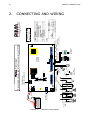
2. CONNECTING AND WIRING
Diagram 3. CAPTAIN 6 wiring diagram
TRU/TRV-100,
GSM-200, SMS-100
Captain 6 (Ver. C )
Key switch/
Remote control
(-)
To zone #6
terminal
JP3: is set to reflect
the EOL loops
Fax, answering
machine, telephones
MIC-200, VU-20U,
GSM-200 Voice Telephone
line-in
(-)
Sirens
Warning. High voltage!
Disconnect AC power and telephone line prior to servicing
(+)
RED
(-)
BLACK
14-16VAC
Transformer
22 JUL 11 22:40
--_----FB__--A-_
4 (IN)
3 (OUT)
2 (+)
1 (-)
BUS
To Expanders
& Keypads
(+)
To zone
input Fire/Smoke
Detector
Z1Z2Z3Z4Z5(-)
N.O./N.C.,
2 EOL
Resistors
N.O.,
1 EOL
Resistor
N.C.,
1 EOL
Resistors
N.O.N.C.
AAAAA
T
T
T
T
T: Tamper
A: Alarm
R2R1R1R1
-
AC
U11
TRANSMITTER
PIMA-6
JP3
F3
+V
KEYPAD
Z1Z2Z3Z4Z5Z6
Z O N E S +VSMOKE PGMSRN
OUTPUTS-
1KEYPADOUTLINE
TELEPHONE
SET
-AUDIO
IN
F2
Z7Z8234
+INOUT-EGND
+
F1
P/N 3610105 Rev. C
Rechargeable
Lead-Acid battery
BATT
-
Earth
Ground
Detector’s
voltage (+)/(-)Dry contact
zone inputs

Captain 6 Installation Guide
11
2.1 The system’s BUS
The system’s BUS is made of 4 wires: 2 for Power - (+)/(-) and 2 for DATA - (IN)/(OUT).
The BUS uses PIMA proprietary protocol.
The overall length of the BUS cannot exceed 500 meters. Call PIMA support when a
longer distance is required.
2.2 Z1-Z6 zones and power
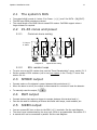
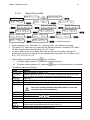
2.2.1 Common zone wiring
Diagram 4. Optional zone wiring
2.2.2 EOL resistor loops
To set a zone as an EOL resistor loop, see the “Zone Characteristics” menu, section 5.1.2.
Set the number of EOL resistors (one or two) per system, in the “Config. 5” menu. See
section 5.4.4.1.
2.3 SMOKE output
Connect smoke or fire detector’s power between this terminal and (+).
When the alarm is set off, the output is disconnected for a minute to reset the detector.
To manually reset the output,
2.4 PGM output
Connect devices that require a trigger to operate, between this terminal and (+).
Can also be used for indicating on alarms and faults with lamps, vocal modules, etc.
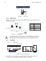
2.5 SIREN output
You can connect DC siren or Horn to the SRN (+)/(-) terminals. See the next diagram.
The siren’s type is determined by the siren tone, which is programmable. See section 5.3.
A second siren can be connected in parallel. See the next diagram.
Z1Z2Z3Z4Z5(-)
N.O./N.C.,
2 EOL
Resistors
N.O.,
1 EOL
Resistor
N.C.,
1 EOL
Resistors
N.O.N.C.
AAAAA
T
T
T
T
T: Tamper
A: Alarm
R2R1R1R1

Captain 6 Installation Guide
12
Diagram 5. Siren wiring
2.6 KEYPAD
Keypads are connected to the control panel’s KEYPAD terminals over the BUS. See the
next figure and table.
Diagram 6. Keypad wiring
Keypad
Control Panel
1 -
1 -
2 +
+2
3 OUT
3 IN
4 IN
4 OUT
The keypads power should only be used for keypads and expanders.
The BUS wires should not be passed too close to telephone wires.
2.7 AUDIO
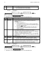
2.7.1 MIC-200
Diagram 7. MIC-200 wiring diagram
The MIC-200 is a microphone that is used for listen-in, when the alarm is set off.
To program a zone to activate the MIC-200, follow the next steps:
CAPTAIN 6
Sirens
+V
SMOKE PGM
SRN -
1
-2 3 4
+ IN OUT
OUTPUTS KEYPAD
+
Control panel
MIC-200
(-)12(+) CON.OUT TAMP
Tamper
MIC-200
(-)12(+) CON OUT TAMP
+V
SMOKE PGM
SRN -
1KEYPAD OUT
-AUDIO
IN
2 3 4
+IN OUT -
+
OUTPUTS
(-)
(+) AUD IN
PGM
(+) CON OUT
To a zone
input

Captain 6 Installation Guide
13
In the “Zone responses” screen (see section 5.1.2), go to the zone that should
activate the MIC-200 and set “G” (PGM) to “+”. This will set the zone to trigger the
PGM output, to which the MIC-200 is connected, when the zone is triggered.
In the “Config 3” (see section 5.4.3) set “G” (delayed PGM) to “+”1. This will delay
the triggering of the PGM output, so the dialer can call the subscriber first.
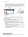
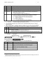
2.7.2 VU-20(U)
Diagram 8. VU-20(U) wiring diagram. The Yellow & white wires are not in use!
The VU-20(U) is a voice module that can play a recorded message over the phone,
when the alarm is set off.
The message is played instead of the synthesized siren sound and can contain, for
example, the zone name where the alarm was set off.
The trigger to the voice module can come from either the SMOKE or PGM outputs.
To program a zone to trigger the VU-20U, follow the next steps:
In the “Zone responses” screen (see section 5.1.2), go to the zone that should
trigger the VU-20U and set “G-PGM” or “F-Fire” to “+”, so the zone will trigger the
PGM/SMOKE output, to which the VU-20N will be connected, when the zone is
triggered.
If the module will be triggered by the PGM output, in the “Config 3” screen, set “V-
Voice unit” and “G-delayed PGM” to “+” (see section 5.4.3).
If the module will be triggered by the SMOKE output, in the “Config 5” screen, set
“S-delayed SMOKE” to “+” (see section 5.4.5).
This will cause the control panel to play the recorded messages and to delay the
triggering of the output.
1 You cannot program a delay for the PGM output and the SMOKE output together. In such a case, the
system ignores the SMOKE delay.
+VSMOKE PGMSRN
OUTPUTS-
1KEYPADOUT
-AUDIO
IN
234
+INOUT-
+
Control panel
Blue
Red
Black
Green M1
M2
GND
+12V
Audio
VU-20(U)
CONT.
V
(+) AUDIO
IN
VU-20(U)
GND
)-(
PGM/
SMOKE
Blue
Red
Black
Green
Yellow
White
Loose
Control panel

Captain 6 Installation Guide
14
2.7.2.1 Recording a message
Diagram 9. VU-20(U) module
1. Switch the module’s REC/PLAY button to the REC position (down).
11. Press and hold the M1 or M2 buttons (the red LED should illuminate) wait one second (for
the recording to start) and record your message. Speak up loudly and clear, 20 cm away
from the module. The message should not exceed 20 seconds.
12. When you finish recording, release the button and switch the REC/PLAY button back to “PLAY”.
13. Test your recording by triggering an alarm.
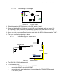
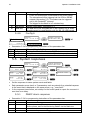
2.7.3 Connecting the GSM-200
Diagram 10. GSM-200 wiring
The GSM-200 is PIMA’s cellular module.
To connect GSM-200:
Connect the GSM-200 YELLOW wire to AUDIO IN;
Connect the ORANGE wire to AUDIO OUT;
Connect the serial wire braid between the module and the TRANSMITTER terminal
on the control panel.
VU -20 U
Audio
+12 V
GND
M1
M2 PLAY
REC
LED
M1 M2
CONT
Orange
Yellow
OUT IN
GSM-200
OUTLINE
TELEPHONE
SET
AUDIO
IN
-EGND
TRANSMITTER
TRANSMITTER
BATT
AUDIO

Captain 6 Installation Guide
15
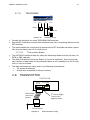
2.7.4 TELEPHONE
Diagram 11. Telephone wiring
Connect the telephone line wires TELEPHONE LINE terminals.
Use the SET terminals to connect other telephone sets, fax or answering machine to the
SET terminals.
This setup enables the control panel to disconnect the SET terminals and make a phone
call, when an alarm is set off or a fault occurs.
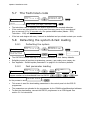
2.7.4.1 The system dialer
The CAPTAIN 6 includes a dialer for calling the Monitoring Station and the end user, via
PSTN or GSM networks.
The dialer first calls the Monitoring Station (if you are a subscriber), then the end user;
each number is called twice and a synthesized alarm or voice message (if a VU-20 voice
unit is in use) is sounded.
The dialer terminates the calling cycle in the following circumstances:
The system is disarmed;
All calls were completed (2 calls per number).
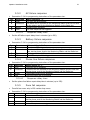
2.8 TRANSMITTER
Diagram 12. Radio transmitter wiring
Line-in
LINE
TELEPHONE
SET
DIO
INEGND
Line-out
TRV/TRU-100
Control Panel
To the
System F2 Program
TRANSMITTER
2nd channel trigger.
Connects to a
triggering output
1
Molex female
connectors
harness

Captain 6 Installation Guide
16
The TRANSMITTER terminal is used for connecting (one by one) PIMA’s TRV/TRU-100
long-range radio transmitters, The GSM-200 cellular module and the SMS-100 module.
To use the radio transmitters, connect them between the “To the system” terminals and
the control panel’s TRANSMITTER socket.
To use the second channel2, connect the wire to a triggering output, e.g., PGM.
2.9 JP3: EOL resistor jumper
Set the JP3 jumper, according to the EOL resistor loops. See the next table.
Resistors (KΩ)
Short pins
10, 13 (default)
10, 10
5.1, 6.8
No jumper
2.10 AC
The cross-section area of the AC wires must be at least 0.75mm2.
The hole through which the main cable passes must have either a grommet or bushing.
The wires must be tied together with a cable tie. The flammability of the cable tie must
be UL 94 V-2 or better.
Connect the wires to the AC terminals of the transformer housing.
Check the continuity between the PCB grounding holes and the grounding of the
premises. The resistance must be less than 1.
The AC voltage must be supplied from a transformer (2A/16VAC).
Do not connect the control panel to a direct power source!
The system should be connected to an automatic circuit breaker.
If Earth Grounding is required, connect it to the EGND terminal on
the PCB. See section 1.7.
2.11 BATTERY
Connect a rechargeable Lid-acid 12V battery.
The charging voltage is 13.8VDC.
The system performs a load test in the following:
Every time it is armed;
Every 4 hours;
Upon connecting to power;
The battery’s voltage is checked every 3 minutes;
To manually test the battery -
If the test fails, the system will respond as programmed in the “System responses” screen
- sounding the siren, calling the Monitoring Station, etc. See section 5.1.3.
2 The second channel must be in the same range (VHF or UHF)
3 2 1
3 2 1

Captain 6 Installation Guide
17
2.12 Zone #6 as key zone
Zone #6 can be used for connecting dry contact key switch, remote control, etc.
Connect the accessories between zone #6 input and a (-) terminal.
Program zone #6 as “Normally Open” (see section 5.4.3).
IF you connect a key, set it as momentary or latch type (see section 5.4.3).
For better protection, it is recommended to connect a 10K EOL resistor in serial to the
key/remote control.
Diagram 13. Key switch wiring
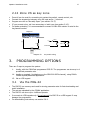
3. PROGRAMMING OPTIONS
There are 3 ways to program the system:
1. Locally, with the PIMA Fast programmer PRG-22. The programmer can store up to 4
predefined parameter sets.
14. Locally or remotely (via telephone or the GSM-200 DATA channel), using PIMA’s
COMAX Upload/Download application.
15. Via an LCD keypad.
3.1 Via the PRG-22
The PRG-22 is a memory card used for storing parameter sets for fast downloading and
quick installation.
The sets are uploaded by the COMAX application.
The PRG-22 can store up to 4 different presets.
It connects to LCD keypads only. Do not connect the PRG-22 to a LED keypad. It may
damage the programmer.
For downloading instructions, see section 5.8.2.
(-)
N.O.
N.C.
Captain 6
RR
Key switch
(-)
Zone # 6
Z O N E S
-Z1 Z2 Z3 Z4 Z5 Z6
R

Captain 6 Installation Guide
18
Diagram 14. Connecting PRG-22 to LCD Keypad
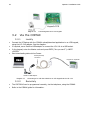
3.2 Via the COMAX
3.2.1 Locally
Connect the PC/laptop with the COMAX upload/download application to an LCD keypad,
using the LCL-11A adaptor. See the diagram.
If required, use a Serial-to-USB adaptor to connect the LCL-11A to a USB socket.
In the keypad, enter the Master code and press ENTR (“Are you sure?”)->NEXT-
>ENTER.
Start downloading data via the Comax.
Diagram 15. Connecting a PC with the COMAX to an LCD keypad via the LCL-11A
3.2.2 Remotely
The CAPTAIN 6 can be programmed remotely, via the telephone, using the COMAX.
Refer to the COMAX guide for information.
COMAX
Serial (RS-232)
connector
LCL-11A
Keypad or expander
Serial-to-USB adaptor

Captain 6 Installation Guide
19
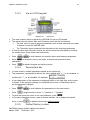
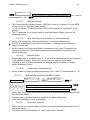
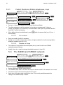
3.2.3 Via an LCD Keypad
Diagram 16. LCD screen
The most common way to program the CAPTAIN 6 is via an LCD keypad.
The system has two menus: User and Technician, each with its own screens:
The User menu is used to program parameters such as time, date and user codes.
To access it, enter the MASTER code.
The Technician menu contains all the technical and the reporting parameters.
In both the User and Technician menus, the various screens are accessed by pressing
the number keys. Some menus have sub-menus.
Press / to scroll between the number menus and between parameters.
Press to access the menu, and again, to access sub-menus and store
parameters.
Press to discard changes and exit the menus.
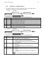
3.2.4 Parameters bar
In some screens, multiple parameters appear as an options bar.
The parameters, represented by letters, are either marked with “+”, i.e. are enabled, or
marked with “-”, i.e. are disabled. For example:
A short description of the parameter is displayed briefly on the right side, as the curser
is moved. In the previous example, the parameters are zone #1 characters and the
current parameter is Bypass.
Press / to scroll between the parameters on the same screen.
Press (toggle mode) to set as “+” (enable) or “-” (disable).
To save and move the cursor to the next parameter, press
In the zone characters screens, press a number between 1-6 to display the desired
zone, or press to display the next zone without saving.
3.2.5 Default factory codes
CAPTAIN 6 factory default codes are as follows:
Master: 5555 Technician: 1234
ENTR
BOFHIDE Bypass
---++-- Zn.Char1
ENTR

Captain 6 Installation Guide
20
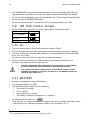
3.3 Initializing the keypad
Upon connecting the keypad to power a long tone is sounded, followed by the next
initialization screens:
Keypad Ver. 1.15
Keypad ID:0
Starting
Please wait...
Clock 00:00
------
. . . . . . . .
The first screen displays the keypad version and ID.
The third is the system’s main screen. It shows the hour and the zones’ status
indicators.
The word “Clock” and the flashing hour indicate that the time is not set and that it
should be (see section 3.4). Because of that, the RED Fault LED will be flashing. Other
faults, if exist, will also be displayed.
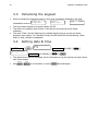
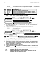
3.4 Setting date & time
MASTER code
HOUR
0 :0
current time (HH:MM)
YEAR MONTH DAY
12 1 1
current date (YY:MM:DD)
The system time must be accurately set for the system to log the events and report them
with a time stamp.
Use / to correct data, or press and start again.
ENTR
ENTR
Page is loading ...
Page is loading ...
Page is loading ...
Page is loading ...
Page is loading ...
Page is loading ...
Page is loading ...
Page is loading ...
Page is loading ...
Page is loading ...
Page is loading ...
Page is loading ...
Page is loading ...
Page is loading ...
Page is loading ...
Page is loading ...
Page is loading ...
Page is loading ...
Page is loading ...
Page is loading ...
Page is loading ...
Page is loading ...
Page is loading ...
Page is loading ...
-
 1
1
-
 2
2
-
 3
3
-
 4
4
-
 5
5
-
 6
6
-
 7
7
-
 8
8
-
 9
9
-
 10
10
-
 11
11
-
 12
12
-
 13
13
-
 14
14
-
 15
15
-
 16
16
-
 17
17
-
 18
18
-
 19
19
-
 20
20
-
 21
21
-
 22
22
-
 23
23
-
 24
24
-
 25
25
-
 26
26
-
 27
27
-
 28
28
-
 29
29
-
 30
30
-
 31
31
-
 32
32
-
 33
33
-
 34
34
-
 35
35
-
 36
36
-
 37
37
-
 38
38
-
 39
39
-
 40
40
-
 41
41
-
 42
42
-
 43
43
-
 44
44


Pima Captain 6 Installation guide
- Category
- Touch screen monitors
- Type
- Installation guide
Ask a question and I''ll find the answer in the document
Finding information in a document is now easier with AI
Related papers
-
Pima LCL-11A Installation guide
-
-
-
Pima ALARM User manual
-
-
-
-
-
-
Other documents
-
Cumberland Farm Hand Series Alarm Connection Owner's manual
-
-
Velleman HAM841K User manual
-
teko Astra-10 User manual
-
 T-Minus 7 DAY PROGRAMMABLE DIGITAL TIMER User manual
-
olympia electronics BS-1632 User manual
-
NTI E-AVDS-CELC V3 User manual
-
Inter-m PE-9103N Operating instructions
-
PARADOX MG-6130 Installation guide
-
PARADOX Spectra SP4000 Programming Manual
