Ridetech Complete Air Suspension System | 1968-1972 GM A-Body Operating instructions

Type
Operating instructions

This manual is also suitable for

1812-482-2932
Installation
Instructions
Recommended Tools
www.ridetech.com
Front Components:
11243001 Front ShockWaves
11222899 Front Lower StrongArms
11223699 Front Upper StrongArms
11009310 Ridetech Tall Spindle
11249120 Front SwayBar
Rear Components:
11246699 Rear Upper StrongArms
11224499 Rear Lower StrongArms
11227299 Axle R-Joint & Installation Tool
11225401 Rear ShockWaves
11239122 Rear SwayBar
Miscellaneous Components:
85000000 Spanner Wrench
Table of contents
Pages 2-5................. Front ShockWaves
Pages 6-9................. Front Lower StrongArms
Pages 10-15............. Front Upper StrongArms
Pages 16-19............. Tall Spindle
Pages 20-22............. Front SwayBar
Pages 23-25............. Rear Upper StrongArms
Pages 26-28............. Rear Lower StrongArms
Pages 29-33............. Front Axle Housing R-Joint & Tool
Pages 34-40............. Rear ShockWave Kit
Pages 41-44............. Rear SwayBar
1968-1972 GM “A” Body Air Kit
Installation Instructions
Part # 11240298 - 1968-1972 GM “A” Body HQ ShockWave System
REV7 8/15/23
2
www.ridetech.com
Installation
Instructions
Recommended Tools
www.ridetech.com
Part # 11243001 - 68-72 GM A-Body Front HQ Series Shockwave
1000 Series Bellow, 2.75” Stud/Eye 3.6” Shock
Installation Instructions
ShockWave Dimensions:
Center of bearing to Center of bearing:
Compressed: 11.05”
Ride Height: 12.85”
Extended: 14.05”
THE DELRIN BALL REQUIRES A 3/4” HOLE FOR THE FLANGE TO
GO THROUGH. THIS CAN BE DRILLED WITH A UNIBIT.
Table of contents
Page 3.......... Included Components
Page 4-5...... Shockwave Installation
3812-482-2932
Installation
Instructions
Major Components .....In the box
Item
#Part # Description QTY
1 982-10-803 3.6” Stroke HQ Series Shock 2
2 90009989 2.75” Stud Top (Installed on Shock) - Includes Adjuster Knob & Screw 2
3 24090199 1000 Series 6.5” Double Convoluted AirSpring 2
4 234-00-153 AirSpring Locking Ring (Installed on shock) 2
5 99055000 Locking Ring Set Screw (Installed on shock) 2
6 90002062 Spacers - INCLUDED WITH STRONGARMS 4
7 90002313 2.75” Aluminum Stud Top Base 2
8 90001904 Bottom Delrin Ball 2
9 90001903 Top Delrin Ball 2
10 90001902 Delrin Ball Aluminum Top Cap 2
11 99562003 9/16”-18 Thin Nylok Nut 2
12 210-35-120-0 Adjuster Knob - (90009989 assembly) 2
13 90009969 #4-40 X 1/4” SS, 18-8 Pan Head Torx Cap - (90009989 assembly) 2
70012161 2.75” Stud Top Metering Rod (installed in stud top) 2
90001994 5/8” ID Bearing (installed in shock and eyelet) 4
90001995 Bearing Snap Ring (installed in shock and eyelet) 8
3
1
2
45
6
78910 11 12 13
THE DELRIN BALL REQUIRES A 3/4” HOLE FOR THE FLANGE TO GO THROUGH. THIS CAN
BE DRILLED WITH A UNIBIT.
WARNING: ATTEMPTING TO REMOVE THE AIR FITTING WILL DAMAGE IT AND VOID THE
WARRANTY.
4
www.ridetech.com
Installation
Instructions
ShockWave Installation
1. Drill the OEM shock hole out to 3/4”. This
can be done with a Unibit. The Shockwave
top can come in contact with the coil spring
retaining fingers. Test fit the ShockWave to
determine if they need cut off. A die grinder
works well here.
2. Some trimming must also be done on the
outside of the frame pocket to allow clearance
for the Shockwave.
3. To allow clearance for the Shockwave,
some trimming must be done on the inside of
the coil spring pocket as shown by the white
line in the picture. This is best done with
either a cut off wheel or plasma cutter. Grind
all cuts smooth when finished.
Note: It may be helpful to go ahead and install
the lower StrongArms and Shockwaves to
determine exactly what needs to be removed.
2.
1.
3.
DRILL TO 3/4”
CUT OFF FINGERS
5812-482-2932
Installation
Instructions
ShockWave Installation
Note: The airline must also be routed at this
time. It can be ran through the subframe to-
ward the rear of the vehicle.
4. The air fitting location can be rotated by
twisting the bellow assembly separate of the
shock. Place the Shockwave into the coil spring
pocket with the stud sticking through the OEM
shock hole. See assembly Diagram 4. OEM
Shock hole must be drilled out to ¾”
1. Stud top aluminum base
2. Delrin ball lower half
3. Delrin ball upper half
4. Aluminum cap
5. 9/16” SAE Nylok jam nut
6. Threaded stud (screwed onto shock shaft)
7. Rebound adjusting knob
8. Screw
5. Raise the lower arm up to the Shockwave
and bolt them together using the 1/2” x 3 ¼”
bolt and Nylok supplied w/ the lower arms. An
aluminum spacer will be on each side of the
bearing. Torque to 75 ftbs.
6. Raise the lower control arm to full compres-
sion and double-check to make sure the Shock-
wave does not rub on anything at anytime. Al-
lowing the Shockwave to rub on anything will
cause failure and is not a warrantable situation.
7. The best ride quality will occur around 50-
60% suspension travel; depending on vehicle
weight this typically occurs around 85-100 psi.
4.
5.
1. Stud top aluminum base
2. Delrin ball lower half
3. Delrin ball upper half
4. Aluminum cap
5. 9/16” SAE Nylok jam nut
6. Threaded stud (screwed onto shock
shaft)
7. Rebound adjusting knob
8. Screw
6
www.ridetech.com
Installation
Instructions
Recommended Tools
www.ridetech.com
Table of contents
Page 7......... Lower Control Arm Components
Page 8......... Getting Started & Installation
Page 9......... Installing Spindles and Steering Stop
Part # 11222899 - 1964-1972 GM A-Body Front Lower StrongArms
1964-1972 GM A-Body Lower StrongArms
Installation Instructions
7812-482-2932
Installation
Instructions
1
2
3
4
5
6
3
7
8
9
10
7
8
6
Lower Control Arm Components .....In the box
Driver Side Shown
Item
#Part Number Description QTY
1 90001224 Driver Lower Control Arm (Shown) 1
1 90001225 Passenger Lower Control Arm 1
2 90000898 Lower Ball Joint Assembly - Proforged # 101-10013 2
3 70010759 Delrin Bushing - with 2” Diameter Ledge 8
4 90002062 CoilOver Bearing Spacers 4
5 90000516 1/2” ID Inner Sleeve 4
6 99501005 1/2”-13 x 3 1/2” Hex Bolt 6
7 99502009 1/2”-13 Nylok Nut 6
8 99503014 1/2” SAE Flat Washer 6
9 99371005 3/8”-16 x 1 1/4” Hex Bolt 2
10 99372012 3/8”-16 Hex Nut 2
8
www.ridetech.com
Installation
Instructions
Getting Started.........
Congratulations on your purchase of the Ridetech A-Body StrongArms. These StrongArms have been
designed to give your A-Body excellent handling along with a lifetime of enjoyment. Some of the key features
of the TruTurn System: Balljoint angles have been optimized for the lowered ride height, Delrin bushings are
used to eliminate bushing deflection along with providing free suspension movement through the entire
travel. The Geometry has been optimized for excellent handling, driveabilty and minimal bumpsteer. The
Delrin bushings are made from a material that is self lubricating so no grease zerks are needed.
Note: These control arms are designed for use with the Ridetech CoilOvers and the MuscleBar swaybar.
The factory shocks and springs or the factory sway bar will not fit these arms.
Installation
1. Remove the entire lower control arms from the car. If you are replacing the upper control arms and
spindle, remove them too. Refer to a Factory Service Manual for the proper method.
2. Drill the factory upper shock mounting hole to 3/4”. This can be done easily with a Unibit.
3. 3. After removing the factory lower control arm,
clean the bushing mounting surfaces on the
frame. The Control Arms are marked “D” for
Driver and “P” for Passenger. The Ballpoint Pin
points up and the Sway bar mount is on the front
side of the arm. Install a 1/2” flat washer on
each of (2) 1/2”-13 x 3 1/2” bolts. Insert the bolt/
washers through the mounting holes. Install a
1/2” flat washer and 1/2”-13 nylok nut. Torque
to 75 ft-lbs.
Note: On some cars the frame brackets may
be pinched and will need to be spread back
apart to allow the bushing to slide in.
Install the CoilOvers at this time.
Refer to the CoilOver instructions
for Assembly.
4. Insert the Bearing Spacers into the lower shock
bearing. The SMALL end goes into the bearing.
Swing the Control Arm up, line up the 1/2” holes
with the bearing spacers, insert 1/2”-13 x 3 1/2”
bolt. Install a 1/2” flat washer and nylok nut.
Torque to 75 ft-lbs. Note: The shock bolt will
need to be installed from the rear with the
threads pointing to the front of the car.
DRIVER
4.
9812-482-2932
Installation
Instructions
Installing Spindle & Setting Steering Stop
5. Attach the Spindle to the control arms.
Torque Specs:
Lower Balljoint - 65 ftlbs and tighten to line up
cotter pin.
Install the Cotter Pin after tightening the ball
joint nut.
6. Thread the 3/8”-16 nut onto the 3/8”-16
x 1 ¼” bolt. Thread it into the front hole of
the ball joint plate. You will need to adjust the
steering stop to suite your needs. This setting
will vary depending on wheel and tire size and
other suspension components. Torque to 12
ft-lbs.
5.
6.
7. Tighten all fasteners. If you are going to install the Ridetech MuscleBar, now is a good time to do it.
Suggested Alignment Specs:
Camber: Street: -.5 degrees
Caster: Street: +3.0 to + 5.0 degrees
Toe: Street: 1/16” to 1/8” toe in
10
www.ridetech.com
Installation
Instructions
Recommended Tools
www.ridetech.com
Table of contents
Page 11......... Upper Control Arm Components
Page 12......... Getting Started
Page 13......... Caster Explained
Page 14......... Offset Upper Control Arm Crossshaft
Page 15......... Installing Spindle and Alignment
Part # 11223699 - 1964-1972 GM A-Body Front Upper StrongArms
1964-1972 GM A-Body Upper StrongArms
Installation Instructions
REV3 5/16/23
11 812-482-2932
Installation
Instructions
1a
2
2
2
34
5
6
7
8
9
10
11
12
5
8
12
Upper Control Arm Components .....In the box
Driver Side Shown
Item
#Part Number Description QTY
1a 90001222 Driver Upper Control Arm (Shown) 1
1b 90001223 Passenger Upper Control Arm 1
2 90000908 kit Upper Ball Joint Kit - Proforged # 101-10015 2
3 90003375 Caster Slug Crossshaft 2
4 70010883 Caster Slug 4
5 70010759 Outer Delrin Bushing with 2” Lip 4
6 70010827 Inner Delrin Bushing with 1.75” Lip 2
7 70010826 Inner Delrin Bushing with No Lip 2
8 90002737 Aluminum T-Washer 4
9 99253012 1/4” SAE Flat Washer 8
10 99753007 3/4” x 1 3/4” Flat Washer 2
11 99183002 M18 Flat Washer 2
12 99622005 5/8”-18 Lock Nut 4
99433004 7/16” USS Flat Washer - NOT SHOWN 4
12
www.ridetech.com
Installation
Instructions
Getting Started.........
Congratulations on your purchase of the Ridetech A-Body StrongArms. These StrongArms have been
designed to give your A-Body excellent handling along with a lifetime of enjoyment. Some of the key features
of the TruTurn System: Balljoint angles have been optimized for the lowered ride height, Delrin bushings are
used to eliminate bushing deflection along with providing free suspension movement through the entire
travel. The Geometry has been optimized for excellent handling, driveabilty and minimal bumpsteer. The
Delrin bushings are made from a material that is self lubricating so no grease zerks are needed.
When assembling the Control Arms tighten the cross shaft nuts enough to create
drag on the delrin bushings, the arm should still move through its travel by hand.
Installation
1. Remove the entire upper control arms from the car. If you are replacing the lower control arms and
spindle, remove them too. Refer to a Factory Service Manual for the proper method.
2.
3.
2. The Upper Control Arm is attaching the
factory mount using factory hardware. The
driver side arm is shown in Figure “2”. The
Balljoint located on the arm to the front of the
car. Install the Ball Joints in the control arms
using the illustration on the previous page as
a reference. Torque the hardware to 15 ftlbs.
3. The Upper Control Arm is attaching the
factory mount using factory hardware with the
supplied 7/16” Flat Washer under the OEM
Nut. Torque the nuts to 50 ft-lbs. The driver
side arm is shown in Figure “2”. The Arrow
on the Cross shaft points to the front of the car.
Page 4 & 5 has information about Caster and
the Caster Slugs.
13 812-482-2932
Installation
Instructions
Caster Explained
6.50”
6.50”
6.50”
1.203”
1.078”
0.953”
1/8” Forward or Back
Centered
1/4” Forward or Back
These StrongArms come equipped with a changeable caster slug setup. This allows you to add or remove
caster from the front suspension, if desired. The caster slugs that come supplied in the kit are setup to be
centered. The caster slugs allow you to add or remove caster without having to use a stack of shims. If
more or less caster is desired, optional slugs can be purchased from Ridetech or your Ridetech dealer.
1/8”= 70010882
1/4”= 70010881
Caster Explained:
To understand caster you need to picture an imaginary line that runs through the upper balljoint and ex-
tends through the lower balljoint. From the side view the imaginary line will tilt forward or backward. The
tilting of this imaginary line is defined as caster.
Caster is measured in degrees by using a caster gauge. If the imaginary line described above tilts towards
the back of the vehicle at the top, then you have positive caster. If the imaginary line tilts forward then
you have negative caster.
Positive caster provides the directional stability in your vehicle. Too much positive caster will make the steer-
ing effort difficult. Power steering will allow you to run more positive caster. Negative caster requires less
steering effort but will cause the vehicle to wander down the highway.
70010883
70010882
70010881
Front
14
www.ridetech.com
Installation
Instructions
Offset Upper Control Arm Shaft
FRAME
FRAME
STREET
WHEEL SIDE
.375”
.532”
WHEEL SIDE
TRACK
The cross shaft that is used in the upper control arms is offset. The offset combined with the caster slug
option allows you to achieve the alignment setting you desire with minimal shims. To change the direction
the Icon faces simply spin the cross shaft in the control arm.
If you are after a Street Alignment bolt the upper control arm to the frame mount with the arm offset to
the outside of the car. The Ridetech Icon and Caster Slugs will be facing the wheel.
If a more aggressive Track or Autocross alignment is desired, bolt the control arm to the frame bracket
with the arm offset to the inside of the car. The Ridetech Icon and Caster Slugs will be facing the engine.
15 812-482-2932
Installation
Instructions
Installing Spindle and Alignment
4. Attach the Spindle to the control arms.
Torque Specs:
Upper Balljoint - 50 ftlbs and tighten to line up
cotter pin.
Install the Cotter Pin after tightening the ball
joint nut.
4.
5. Tighten all fasteners.
When assembling the Control Arms tighten the cross shaft nuts enough to create
drag on the delrin bushings, the arm should still move through its travel by hand.
Suggested Alignment Specs:
Camber: Street: -.5 degrees
Caster: Street: +3.0 to + 5.0 degrees
Toe: Street: 1/16” to 1/8” toe in
16
www.ridetech.com
Installation
Instructions
Recommended Tools
www.ridetech.com
Part # 11009310 - A/F/X Tall Spindle Kit
A/F/X Tall Spindle Kit
Installation Instructions
Table of contents
Page 17......... Included Components and Hardware
Page 18......... Getting Started and Installation
Page 19......... The Finish
THIS SPINDLE IS DESIGNED TO FIT 64-72 GM A-BODY, 67-69 GM F-BODY, AND 68-74 GM X-BODY.
THESE SPINDLES ARE SYMMETRICAL, THEY AREN’T SIDE SPECIFIC UNTIL THE STEERING ARM IS
BOLTED ON.
THESE SPINDLES ARE A DIRECT REPLACEMENT FOR OEM DISC BRAKE
SPINDLES. IF YOUR CAR HAS DRUM BRAKES, YOU WILL HAVE TO CONVERT
IT TO DISC BRAKES. THEY WILL ACCEPT ANY BRAKE KIT THAT IS DESIGNED
FOR THE OEM DISC BRAKES SPINDLES.
17 812-482-2932
Installation
Instructions
Major Components .....In the box
Item # Part # Description QTY
1 11009307 Spindles (Pair) 1 pair
2 90002743 3/4”-20 Spindle Nut Kit 1 kit
1
2
3
4
5
6
Item # Part # Description Usage QTY
Hardware
3 99501009 1/2”-20 x 1 3/4” Hex Bolt Steering Arm to Spindle 2
4 99502005 1/2”-20 x 2” Hex Bolt Steering Arm to Spindle 2
5 99503015 1/2” Split Lock Washer Steering Arm to Spindle 4
6 99503014 1/2” SAE Flat Washer Steering Arm to Spindle 4
18
www.ridetech.com
Installation
Instructions
Getting Started.........
These spindles will fit ’67-69 Camaro, ’64-’72 Chevelle, and ’68-’74 Nova. They will provide a 2” drop,
and are taller than stock to improve the car’s cornering ability. The raised upper ball joint induces negative
camber gain and positive caster gain. This helps keep the tires flat on the pavement when cornering. This
camber action change also raises the roll center for less body roll, and transfer the car’s center of gravity
inboard in the turn as well. You will see an appreciable improvement in handling.
These spindles are designed around stock disc brake spindles and will accept any disc brake set up designed
for those. The only modification we discovered to be necessary was a small trim on the bottom
of the stamped ¼” steel caliper bracket that holds the caliper. It is an area that is not stressed and
will not cause any loss of strength. Trim only enough to make the caliper bracket clear the spindle. If you
are using the factory dust shields, they will also require trimming. If your car came with drum brakes, be
sure to swap to the appropriate disc brake master cylinder and valving.
Installation
IF YOU HAVEN’T ALREADY DONE SO,
REMOVE THE OEM SPINDLE. IF REUSING
THE EXISTING CALIPERS, BE SURE TO
SUPPORT THEM TO KEEP FROM PUTTING
UNWANTED STRESS ON THE BRAKE LINES.
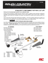
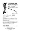
1 & 2. Remove the OEM steering arms from
the spindles that were removed from the car.
The steering arm will bolt to the BOTTOM set
of holes in the spindle using the supplied 1/2”
hardware. The mounting bosses of the steering
arm are 2 different thicknesses. The thicker
boss uses a 1/2”-20 x 2” hex bolt. The thin
boss will use a 1/2”-20 x 1 3/4” bolt. Install a
1/2” split lock washer followed by a 1/2” SAE
flat washer on each bolt. We suggest using
RED Threadlocker on the steering arm
mounting hardware. Line up the steering
arm mounting holes with the bottom 2 holes of
the spindle. Insert the 2” long bolt through the
thick boss and the 1 3/4” long bolt through the
thin boss, threading the bolts into the spindle.
Torque the steering arm hardware to 100 ftlbs.
NOTE: Some steering arms have 7/16”
mounting holes, they will need to be drilled out
using a 1/2” drill bit.
2.
1.
19 812-482-2932
Installation
Instructions
The Finish
3. Attach the spindles to the control arms. Torque the ball joints and tie rods end using the torque specs
below.
Torque Specs:
Lower Ball Joint - 65 ftlbs and tighten to line up cotter pin.
Upper Ball Joint - 50 ftlbs and tighten to line up cotter pin.
Tie Rod End - 35 ftlbs and tighten to line up cotter pin.
Wheel Bearing Tightening:
While turning the rotor, tighten the nut to 12 ftlbs with a torque wrench. Back off the nut one flat and
insert the cotter pin. If the slot and pin hole don’t line up, back off the nut an additional half flat or less as
required to insert the pin. Note: Bearings should have zero preload and .001” to .008” of end movement.
Bend the ends of the cotter pin, replace the dust cap. On a disc brake with the caliper removed, it’s normal
to have a slight amount of play detectable in the bearing.
5. Recheck all hardware before driving.
6. PUMP THE BRAKE PEDAL BEFORE DRIVING TO RESET THE BRAKE PADS TO THE ROTOR. IF
YOU HAD THE CALIPERS REMOVED, BLEED THE BRAKE SYSTEM.
Suggested Alignment Specs:
Camber: Street: -.5 degrees
Caster: Street: +3.0 to + 5.0 degrees
Toe: Street: 1/16” to 1/8” toe in
20
www.ridetech.com
Installation
Instructions
Recommended Tools
www.ridetech.com
Table of contents
Page 21......... Included Components and Hardware List
Page 22......... SwayBar Installation
Part # 11249120 - 1968-1972 GM A-Body Front SwayBar
1968-1972 GM A-Body Front SwayBar
Installation Instructions
Hardware Torque Specifications
5/16”-16................. 17 ftlbs
3/8”-16................... 30 ftlbs
REV2 5/2/22
  • Page 1 1
  • Page 2 2
  • Page 3 3
  • Page 4 4
  • Page 5 5
  • Page 6 6
  • Page 7 7
  • Page 8 8
  • Page 9 9
  • Page 10 10
  • Page 11 11
  • Page 12 12
  • Page 13 13
  • Page 14 14
  • Page 15 15
  • Page 16 16
  • Page 17 17
  • Page 18 18
  • Page 19 19
  • Page 20 20
  • Page 21 21
  • Page 22 22
  • Page 23 23
  • Page 24 24
  • Page 25 25
  • Page 26 26
  • Page 27 27
  • Page 28 28
  • Page 29 29
  • Page 30 30
  • Page 31 31
  • Page 32 32
  • Page 33 33
  • Page 34 34
  • Page 35 35
  • Page 36 36
  • Page 37 37
  • Page 38 38
  • Page 39 39
  • Page 40 40
  • Page 41 41
  • Page 42 42
  • Page 43 43
  • Page 44 44

Ridetech Complete Air Suspension System | 1968-1972 GM A-Body Operating instructions

Type
Operating instructions
This manual is also suitable for

Ask a question and I''ll find the answer in the document

Finding information in a document is now easier with AI