Ridetech 1988-1998 Chevy/GMC C1500 2WD Truck | Complete Coil-Over Suspension System Installation guide

Type
Installation guide
1812-482-2932
Installation
Instructions
Recommended Tools
www.ridetech.com
88-98 GM C1500 Coilover System
Installation Instructions
Table of contents
Pages 2-6............ Front Coilovers
Pages 7-10...........Lower StrongArms
Pages 11-15........ Upper StrongArms
Pages 16..............Spindles
Pages 17-20........ Front MuscleBar
Pages 21-38........ Rear 4Link
Pages 39-40.........Rear CoilOver
Pages 41-42.........Final Adjusting and Preloading the Spring
REV8 2/22/23
!!THE SPINDLES IN THIS KIT INCREASE THE TRACK WIDTH 1/4” PER SIDE!!
Part # 11370202 - 88-98 GM C1500 CoilOver System w/Light Duty Spindle
Front Components:
11372899 Front Lower StrongArms
11373699 Front Upper StrongArms
11379301 Front Spindles
11373510 Front Coilovers
11379100 Front MuscleBar
Rear Components:
11377199 Rear Wishbone System
11376510 Rear Coilover Instructions
Miscellaneous Components:
85000000 Spanner Wrench
THE SPINDLES SUPPLIED IN THIS KIT ARE DESIGNED FOR THE LIGHT DUTY BRAKES, 1” ROTORS.
2
www.ridetech.com
Installation
Instructions
Recommended Tools
www.ridetech.com
Part # 11373510 - 88-98 C1500 Front HQ Series CoilOvers
1988-1998 C1500 HQ Series Front CoilOvers
Installation Instructions
THIS COILOVER KIT IS DESIGNED TO BE USED WITH RIDETECH STRONGARMS. THIS KIT WILL NOT
WORK WITH OEM CONTROL ARMS.
Table of contents
Page 3......... Included Components
Page 4-7...... CoilOver Installation
3812-482-2932
Installation
Instructions
Major Components .....In the box
14
2
34
5
6
7
8
9
10 1112 13 14 15
16
Item
#Part # Description QTY
1 982-10-803 3.6” Stroke HQ Series Shock 2
2 90009989 2.75” Shock Stud (Installed on Shock) - Includes Adjuster Knob & Screw 2
3 59080850 Coilspring 8” 850lb 2
4 70010828 Delrin Spring Washer 4
5 803-00-199(kit) Lower Spring Adjuster Nut (803-00-199 kit) 2
6 803-00-199(kit) Adjuster Nut Locking Screw (803-00-199 kit) 2
7 90002070 Dropped Upper Spring Mount 2
8 803-00-199(kit) CoilSpring Plate Retaining Ring (803-00-199 kit) 2
9 900001337 Upper Shock Mount 2
10 90002312 2” Stud Top Spacer 2
11 90001287 .5” Upper Delrin Ball Cap 2
12 90001903 Lower Delrin Ball for Shock Stud Top 2
13 90001904 Upper Delrin Ball for Stock Stud Top 2
14 99562003 9/16”-18 Nylok Nut 2
15 210-35-120-0 Adjuster Knob 2
16 90009969 4-40 x 1/4” Pan head Torx Screw 2
70012161 2.75” Metering Rod - Installed in Stud Top 2
90001994 5/8” ID Bearing (installed in shock body & eyelet) 2
90001995 Bearing Snap Ring (installed in shock & eyelet body) 4
4
www.ridetech.com
Installation
Instructions
12
3
4
5
6
7
CoilOver Installation
1. Raise and support truck at a safe, comfortable
working height. Let the front suspension hang
freely.
2. Remove the coil spring, shock absorber,
bump stop, upper control arm, and lower
control arm. Refer to factory service manual for
proper disassembly procedure.
3. Install the CoilOver StrongArms. Refer to the
StrongArm instructions.
4. Drill the OEM shock hole out to 3/4”. A
Unibit stepped drill bit works well for this.
5. The CoilOvers will need to be partially
disassembled to install them into the truck. To
disassemble the CoilOver you need to:
a. Remove Screw (1) from center of
Adjustment Knob (2) using a T10 Torx to
remove Adjustment Knob.
b. Remove Nylok Nut(3), Delrin Upper Cap(4),
Delrin Upper Ball(5) and Billet Upper Mount(6).
c. The Delrin Lower Ball(7) will most likely
be stuck in the shock hole of the billet upper
mount. Remove it for the time being.
Repeat on second CoilOver.
5.
4.
BEFORE AFTER
5812-482-2932
Installation
Instructions
CoilOver Installation
6. The Aluminum Upper CoilOver Support has
the center mounting hole offset as is the shock
mounting hole in the frame. They will need to
be test fitted in each side to check for alignment
of the OEM shock hole and the shock hole in the
aluminum upper mount. It may be necessary
to trim the coil spring retaining fingers to get
proper alignment.
7. They will need to be test fitted in each side to
check for alignment of the OEM shock hole and
the shock hole in the aluminum upper mount.
Due to variances throughout the years of these
trucks being produced, it may be necessary
to trim the coil spring retaining fingers to get
proper alignment. Stick the mount up in the
frame pocket with the large opening down.
Rotate the upper mount to get the shock holes
aligned. Determine the orientation the achieves
the best alignment. If the holes DO NOT
perfectly align, trim the necessary coil spring
fingers to get the mount in the correct position
with the holes aligned.
8. We used a die-grinder with a cut off wheel
to trim the fingers. On some trucks, the holes
will line up without trimming
7.
8.
6.
6
www.ridetech.com
Installation
Instructions
54
3
2
1
A
2
1
CoilOver Installation
9. After hole alignment has been achieved,
reinstall the Bottom Delrin Ball and Aluminum
Upper Mount.
10. Insert the CoilOver with the Aluminum
Upper installed into the OEM coil spring pocket.
You may need to rotate the upper mount while
inserting the assembly to get the best alignment
of the shock holes.
11. Hold the CoilOver in place. Install the Upper
Delrin Ball (1), Aluminum Upper Cap (2), 9/16”-
18 Nylok Nut (3), Adjuster Knob (4), & Adjuster
Knob Retaining Screw (5) on the Stud Top (A)
that is sticking through the frame. See below
for nut tightening.
TIGHTENING THE TOP 9/16”-18 NUT: SNUG
THE NUT DOWN AGAINST THE TOP CAP. YOU
NEED TO BE ABLE TO ARTICULATE THE SHOCK
BY HAND. WE TORQUE THE NUT TO 80 INLBS
USING A 7/8” CROWS FOOT WRENCH ON A
TORQUE WRENCH.
10.
11.
9.
FRAME
7812-482-2932
Installation
Instructions
Recommended Tools
812-482-2932
www.ridetech.com
Table of contents
Page 8......... Lower Control Arm Components
Page 9......... Getting Started & Installation
Page 10....... Installing Spindles
Part # 11372899 - 1988-1998 GM C1500 Front Lower StrongArms
1988-1998 GM C1500 Lower StrongArms
Installation Instructions
8
www.ridetech.com
Installation
Instructions
5
4
2
1
Lower Control Arm Components .....In the box
Driver Side Shown
Item
#Part Number Description QTY
1 90001335 Driver Lower Control Arm (Shown) 1
1 90001336 Passenger Lower Control Arm 1
2 90000897 Lower Ball joint Assembly - Proforged # 101-10054 2
3 90000198 Rear Inner Sleeve - 3.0” Long 2
4 70010759 Delrin Bushing - with 2” Diameter Ledge 8
5 90000199 Front Inner Sleeve - 3.5” Long 2
PARTS NOT SHOWN IN DIAGRAM
90002043 CoilOver Bearing Spacers 4
99501050 1/2”-13 x 2 1/2” Hex Bolt 2
99502009 1/2”-13 Nylok Nut 2
99503014 1/2” SAE Flat Washer 4
9812-482-2932
Installation
Instructions
Getting Started.........
Congratulations on your purchase of the Ridetech C1500 StrongArms. These StrongArms have been
designed to give your C1500 excellent handling along with a lifetime of enjoyment. Some of the key
features of these StrongArms: Balljoint angles have been optimized for the lowered ride height, Delrin
bushings are used to eliminate bushing deflection along with providing free suspension movement through
the entire travel. The Delrin bushings are made from a material that is self lubricating so no grease zerks
are needed.
Note: These control arms are designed for use with the Ridetech CoilOvers and the MuscleBar swaybar.
The factory shocks and springs will not fit these arms.
Installation
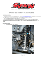
1. Remove the lower control arms from the truck. If you are replacing the upper control arms and spindle,
remove them too. Refer to a Factory Service Manual for the proper method.
3. DRIVER
4.
3. After removing the factory lower control
arm, clean the bushing mounting surfaces on
the frame. The Control Arms are marked “D”
for Driver and “P” for Passenger. The Ball joint
Pin points up and the steering stop is positioned
to the rear of the truck. Fasten the lower arm
to the frame with the OEM hardware. Torque
to 120 ft-lbs.
Note: On some trucks the frame brackets may
be pinched and will need to be spread back
apart to allow the bushing to slide in.
Install the CoilOvers at this time.
Refer to the CoilOvers instructions
for Assembly.
4. Insert the Bearing Spacers into the lower
shock bearing. The SMALL end goes into the
bearing. Swing the Control Arm up, line up
the 1/2” holes with the bearing spacers. Install
a 1/2” flat washers on a 1/2”-13 x 2 1/2”
hex bolt, insert it through the hole. Install a
1/2” flat washer and nylok nut. Torque the
hardware to 75 ftlbs.
10
www.ridetech.com
Installation
Instructions
Installing Spindle
5. Attach the Spindle to the control arms.
Torque Specs:
Lower Balljoint - 94 ftlbs and tighten to line up
cotter pin.
Install the Cotter Pin after tightening the ball
joint nut.
5.
6. Tighten all fasteners. If you are going to install the Ridetech MuscleBar, now is a good time to do it.
Suggested Alignment Specs:
Camber: Street: -.5 degrees
Caster: Street: +3.0 to + 5.0 degrees
Toe: Street: 1/16” to 1/8” toe in
11 812-482-2932
Installation
Instructions
Recommended Tools
Table of contents
Page 12............ Included Components & Getting Started
Page 13-15....... StrongArm Installation
1988-1998 GM C1500 Upper StrongArms
Installation Instructions
Part # 11373699 - 88-98 GM C1500 Front Upper StrongArms
www.ridetech.com
12
www.ridetech.com
Installation
Instructions
Lower Control Arm Components .....In the box
1.
Getting Started.........
1. The OEM upper control arms will need to be
removed from the truck. Start by disconnecting
the brake line from the upper control arm.
Disconnect the ABS cable from the control
arm. You will need to remove one of the ball
joint bolts to disconnect it.
DRIVER TOP
VIEW
4
1
Item # Part Number Description QTY
1 90001333 Driver Upper Control Arm 1
1 90001334 Passenger Upper Control Arm 1
2 90000900 Upper Ball Joint - Proforged # 101-10053 2
3 70010759 Delrin Control Arm Bushing 8
4 90001097 Delrin Bushing Inner Sleeve 4
99251020 1/4”-20 X 1/2” Thread Forming Screw - Not Shown 4
13 812-482-2932
Installation
Instructions
StrongArm Installation
2. 2. Remove the Upper Control Arms. The
Camber Bolts need to be reinstalled in the
same positions they are removed from. We
recommend marking their positions for
reassembly. Refer to the factory service manual
for disassembly procedure. After removing the
factory upper control arm, clean the bushing
mounting surfaces on the frame.
3. If your truck has never needed the caster or
camber changed, it may still have the locating
slugs in the upper control arm mounts. See
Image 3. Skip to Step 6 if your truck has
already had the locating slugs removed.
4. They make a tool for removing the locating
slugs or you can knock them out with an air
chisel. It is best to use a blunt tool in the air
chisel to knock them out. If you are having a
shop align your truck, they will have the tool
needed to knock the slugs out.
4.
3.
14
www.ridetech.com
Installation
Instructions
StrongArm Installation
6.
7.
5. 5. Install the Ball Joint using the supplied
5/16” Hardware. Insert the ball joint into the
arm using Image 5 as a reference. Insert a
5/16”-18 x 1 1/4” Bolt therough the ball joint
and plate. The threads should pointing the
same direction as the ball joint pin. Install a
5/16” Flat Washer and 5/16”-18 Nylok Nut on
the threads of each bolt. Torque to 25 ftlbs.
6. Insert the control arm into the OEM location.
The Brake Line Tab is positioned to the
front of the vehicle. Use the Illustration on
page 2 to help aid in installing the correct
control arm in the correct location.
7. Bolt the arm to the frame using the factory
camber bolts. If you marked the bolts during
disassembly, reinstall them in the correct
position and tighten. Torque to 140 ft-lbs.
15 812-482-2932
Installation
Instructions
8.
StrongArm Installation
8. Slide the ball Joint pin into the spindle and
install the castle nut on each one. Torque the
ball Joint nuts and install cotter pins in each
one.
Ball Joint nut Torque Specs:
Torque to 50 ft lbs and then tighten nut to align
cotter pin hole not exceeding 90 ft lbs.
9. Attach the ABS cable to the control arm
by removing the nut/washer from the front,
inner bolt. Slide the bracket onto the bolt and
replace the washer & nut. Torque the nut to
25 ftlbs.
10. Attach the brake line bracket to the new
upper control arm using the supplied thread
forming bolts. Align the bracket with the tab
on the control arm. Attach it using the thread
forming bolts supplied with the kit. These can
be threaded in using a ratchet. Put downward
pressure on the bolt while turning them.
Torque them to 15 inlbs.
11. Tighten all fasteners.
12. Have the front end aligned.
Suggested Alignment Specs:
Camber: Street: -.5 degrees
Caster: Street: +3.0 to + 5.0 degrees
Toe: Street: 1/16” to 1/8” toe in
10.
9.
16
www.ridetech.com
Installation
Instructions
Recommended Tools
Part # 11379301 - 1988-1998 C1500 Drop Spindles
www.ridetech.com
1988-1998 C1500 Drop Spindles
Installation Instructions
Torque Specs:
Splash Shield to Spindle: 19 ftlbs
Upper Balljoint: 74 ft lbs and then tighten nut to align cotter pin.
Lower Balljoint: 94 ft lbs and then tighten nut to align cotter pin.
Outer Tie Rod: 46 ftlbs and then tighten nut to align cotter pin.
THESE SPINDLES ARE DESIGNED FOR THE LIGHT DUTY BRAKES, 1” THICK ROTORS.
!!THESE SPINDLES INCREASE THE TRACK WIDTH 1/4” PER SIDE!!
REV2 7/1/20
17 812-482-2932
Installation
Instructions
Recommended Tools
www.ridetech.com
Table of contents
Page 18......... Included Components and Hardware List
Page 19......... SwayBar Installation
Part # 11379120 - 1988-1998 GM C1500 Front SwayBar
1988-1998 GM C1500 Front SwayBar
Installation Instructions
Hardware Torque Specifications
M10-1.5................. 37 ftlbs
REV3 2/22/23
18
www.ridetech.com
Major Components .....In the box
Part # Description QTY
90001228 Front Sway Bar 1
90001258 Sway Bar End Link T-Bushing 4
70015016 Lined Sway Bar Bushing 2
90002513 Bushing Strap 2
90001257 Bushing Mount Adapter 2
70014491 Locking Ring 2
Getting Started.........
This sway bar kit utilizes a anti-friction lining in the sway bar bushing. The lining allows the sway bar to move freely
and quietly in the bushing. No lubrication is required.
1. Jack the vehicle up to a safe working height and support with jack stands. Make sure the jack stands
are stable before working under the car.
2. Remove the stock sway bar.
OEM FRAME BRACKET NOTE:
Some 88-98 C1500’s have an OEM frame
bracket on the passenger side that the
sway bar bushings attaches to. This
bracket MUST be used with the Ridetech
sway bar!
HARDWARE KIT......99010086
QTY Part Number Description
ADAPTER PLATE
2 99111001 M10-1.5 x 30mm Flat Head
1 90002263 Red Loctite
QTY Part Number Description
BUSHING STRAP
2 99111003 M10-1.5 x 40mm Hex Bolt
2 99111011 M10-1.5 x 20mm Hex Bolt
4 99113001 M10 Split Lock Washer
4 99433002 7/16” SAE Flat Washer
Part # Description QTY
90003543 90 Degree End Link Spacer 2
90003842 90 Degree End Link 2
99115003 M10-1.5 x 115mm Fully Threaded Stud 2
90002930 End Link Kit 2
99112002 M10-1.5 Nylok Nut 2
END LINK ASSEMBLY
OEM
FRAME
BRACKET
19 812-482-2932
6. Hold the Frame Plate up to the OEM holes, the Counter
Sunk hole will he positioned over the front hole with the
slot to the rear. Apply Red Loctite to the Flat Head Bolt.
Thread a Bolt into the rear hole to help keep the plate
straight. Torque the flat head bolt and remove the rear
bolt.
6.
7. Slide the SwayBar into position on the truck with the
SwayBar arms above the tie rods. Install a Lock Washer
& Flat Washer on the each M10 Hex Bolts. A 30mm
goes in the front, with a 40mm going in the rear. Do
NOT complete tighten the hardware at this time.
7.
8. Install a T-Bushing on each of the 90 degree
end links. The t-bushings are installed with the
large diameter against the shoulder of the end
link.
8.
FRONT
FLAT HEAD
SOCKET CAP
SCREW
9. Insert the 90 degree end link/t-bushing into the
swaybar end with the threads pointing toward the
coilspring. Install a 2nd t-bushing with the small
diameter into the swaybar. Install the nut and
torque. Do this for both sides.
9.
4. Open the sway bar bushing at the split and slide
it OVER the swasy bar. Do this for both bushings.
4.
5. Slip the Bushing Straps over the Sway Bar
Bushings.
5.
20
www.ridetech.com
10. Install the End Links using Diagram 10 as a
reference. Install both end links before tightening
the end link hardware. Tighten the end link nut
until it is flush with the end of the bolt, and then
tighten it 2 more complete rounds.
10. 11.
11. Center the swaybar and torque the strap
hardware. Install the stop rings against the swaybar
bushing. The stop rings will go against the inner
side of the bushing. Take the stop rings apart and
reassemble them against the bushing and tighten.
Control Arm
  • Page 1 1
  • Page 2 2
  • Page 3 3
  • Page 4 4
  • Page 5 5
  • Page 6 6
  • Page 7 7
  • Page 8 8
  • Page 9 9
  • Page 10 10
  • Page 11 11
  • Page 12 12
  • Page 13 13
  • Page 14 14
  • Page 15 15
  • Page 16 16
  • Page 17 17
  • Page 18 18
  • Page 19 19
  • Page 20 20
  • Page 21 21
  • Page 22 22
  • Page 23 23
  • Page 24 24
  • Page 25 25
  • Page 26 26
  • Page 27 27
  • Page 28 28
  • Page 29 29
  • Page 30 30
  • Page 31 31
  • Page 32 32
  • Page 33 33
  • Page 34 34
  • Page 35 35
  • Page 36 36
  • Page 37 37
  • Page 38 38
  • Page 39 39
  • Page 40 40
  • Page 41 41
  • Page 42 42

Ridetech 1988-1998 Chevy/GMC C1500 2WD Truck | Complete Coil-Over Suspension System Installation guide

Type
Installation guide

Ask a question and I''ll find the answer in the document

Finding information in a document is now easier with AI