
MAG
BILL ACCEPTOR
Operation and Service Manual


3
TABLE OF CONTENTS
Section 4: Maintenance
Disassembling the MAG ..................................... 12
Disassembling the Chassis .................................. 15
Disassembling the Lower Housing ...................... 17
MAG50 Cleaning Maintenance Procedure ......... 19
Cleaning Salt Water Damage .............................. 20
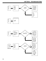
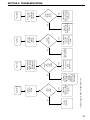
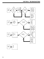
Section 5: Troubleshooting
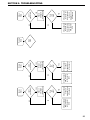
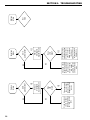
Introduction ......................................................... 21
MAG Diagnostic Flash Codes ............................ 21
Troubleshooting Guide ........................................ 22
Section 6: Parts List
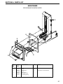
Main Frame (MAG50B/52B/52BX) ................... 27
Main Frame (MAG50SA/52SA) ........................ 28
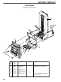
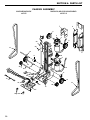
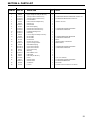
Chassis ................................................................ 29
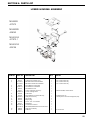
Lower Housing Assembly ................................... 31
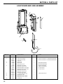
Logic Board and Case Assembly ........................ 32
Intermediate Frame Assembly ............................. 33
Cashbox Assembly .............................................. 33
Harnesses ............................................................ 34
Section 1: General Information
Introduction ........................................................... 4
Models .................................................................. 4
For Your Records ................................................. 4
Features ................................................................. 4
After Unpacking .................................................... 4
Main Logic Board Assembly ................................ 5
Specifications ........................................................ 5
Dimensional Drawing ........................................... 6
Section 2: Installation
Option Switch Settings .......................................... 7
Installing the Bill Validator ................................... 7
Section 3: Operation
Bill Recognition .................................................... 8
Bill Validation ....................................................... 8
Bill Stacking and Credit ........................................ 8
Bill Rejection ........................................................ 8
Component Explanation
Bill Transport and Stacking ........................... 8
Left and Right Alignment Sensors .................. 8
Center Optic Sensor ....................................... 8
Left and Right Optic Sensor ........................... 8
Magnetic Sensor ............................................. 8
Anti-Pullback Levers ...................................... 8
Stacker Home Sensor ..................................... 8
Encoder Sensor ............................................... 8
Component Explanation Drawing .................. 9
Interconnect Drawing (MAG50B/52B) .............. 10
Interconnect Drawing (MAG50SA/52SA) .......... 11

4
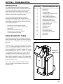
SECTION 1: GENERAL INFORMATION
INTRODUCTION
This manual contains information on installing, operating
and maintaining Coinco's MAG Series bill acceptors.
This manual is intended for owners, route operators and
shop-level technicians as a primary source of informa-
tion. Taking time to read this manual and becoming
familiar with this information will help you obtain the
best performance from your Coinco bill acceptor.
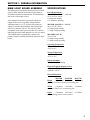
MODELS
MAG Series bill acceptors are self-contained units
designed to work with existing vending machine inter-
faces, plus MDB vendors. Listed below are some of the
models available:
MAG50B MAG bill acceptor, 500 capacity
stacker, 110V AC, Bottler interface
and mask
MAG52BX MAG bill acceptor, 500 capacity
stacker, 24V DC, Bottler mask, MDB
interface only
MAG50SA MAG bill acceptor, 500 capacity
stacker, 110V AC, Snack interface and
mask,
Additional length harness
MAG50B bill acceptors are primarily used in cold drink
vendors which use either the electromechanical, elec-
tronic, or MDB interface. This bill acceptor uses the
"bottler" interface, which communicates to the vendor
through either HIGH LEVEL or MDB communication.
MAG52BX supports MDB communication only.
MAG50SA and MAG52SA bill acceptors are primarily
used in either electronic or MDB snack, coffee or food
machines. These bill acceptors use the "snack" interface
and communicate to the vendor through either PULSE,
SERIAL, PARALLEL or MDB communication.
FOR YOUR RECORDS
A label indicating the model number and serial number is
affixed to the back of the bill acceptor. Refer to the
model and serial number whenever you call upon your
Coinco Service Center for information or service. The
first four digits of the serial number contain the manufac-
turing date code which indicates the beginning of the
warranty period.
EXAMPLE: Serial number 269900135. First and
second digits indicate the week of manufacture. The
third and fourth digits indicate the year (the 26th week
of 1999).
FEATURES
Modular design
Bill Hold Feature.
Center drive belt.
Scalloped bill path for wet bill acceptance.
State-of-the-art electronic logic system
Switch selectable acceptance of the following bills: $1,
$2, $5, $10 and $20.
High capacity bill box.
Vandal resistant design protects against: saltwater, bill
pullback, counterfeit bills.
Utilizes standard mounting and electrical interfaces.
110 and 24 VAC and 24 VDC Multi-Drop Bus
interfaces available.
High impact, non-corrosive plastic construction.
Easily accessible bill path.
Self-diagnostics communicated via status light.
Standard/High Level security switch.
Switch selectable acceptance of bills face up, in one or
both directions.
Optional hasp for locking bill box.
Manufactured and supported by Coinco.
Made in the U.S.A.
AFTER UNPACKING
After unpacking the unit, inspect it for any possible
shipping damage. If the unit is damaged, notify the
shipping company immediately. Only the co-signee (the
person or company receiving the unit) can file a claim
against the carrier for shipping damage. We recommend
that you retain the original carton and packing materials
to reuse if you need to transport or ship your acceptor in
the future.
If the bill acceptor is being stored or used as a spare,
always keep it in its shipping carton when not in use.
This will keep it clean and offer the best protection for
the unit.

5
SECTION 1: GENERAL INFORMATION
MAIN LOGIC BOARD ASSEMBLY
The main logic board contains the microprocessor which
controls all the functions of the bill acceptor based on
information from the vending machine, coin mechanism
and various bill acceptor sensors.
Also contained on the main logic board is the power
supply which receives its primary voltage from the
vending machine. For 117VAC units, the primary AC
voltage is routed to the transformer in the bill acceptor
where it is reduced to 24VAC. This 24VAC is then
routed back to the main logic board where it is rectified
and filtered for logic board operation. For 24VAC and 24
VDC (MDB) units, no transformer is needed. The
primary voltage is rectified and filtered on the main logic
board.
SPECIFICATIONS
Power Requirements
MAG50B, MAG50SA 117V AC
95 to 130 VAC, 60 Hz
0.2 Amp max standby
0.75 Amp max operating
MAG52B, MAG52SA 24V AC
20 to 32 VAC, 60 Hz
0.2 Amp average standby
2.5 Amp average operating
MAG52BX--24V DC
22 to 45 VDC
0.2 Amp average standby
2.5 Amp average operating
Operating Temperature
0°F to 150°F
-18°C to 65°C
Storage Temperature
-22°F to 165°F
-30°C to 74°C
Relative Humidity
5% to 95% non-condensing
Physical Weight in Shipping Carton
5.7 pounds - 117VAC
4 pounds - 24VAC
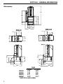
Physical Dimensions
MAG30B MAG50B MAG70B
Height 11.16 inches 11.16 inches 11.16 inches
from top of bill box to bottom of mounting plate
Width 5.26 inches 5.26 inches 5.26 inches
from logic board cover to mounting plate
Depth 4.29 inches 4.92 inches 6.17 inches
from mounting plate to back of stacker

6
3.32
2.87
1.74
MAGxxSA
3.25
.99
2.85
3.32
MAGxxB
Depth
1.21
.53
1.00
4.24
4.97
2.91
Depth
4.231.80
2.26
4.23
6.80
1.33
2.00
3.74
5.26
5.20
4.59
3.25
11.16
Depth
B models SA models
MAG30 4.29 5.03
MAG50 4.92 5.66
MAG70 6.17 6.91
MAG90 8.67* 9.41*
*Add 0.25 for metal cashbox
SECTION 1: GENERAL INFORMATION
Dimensions

7
SECTION 2: INSTALLATION
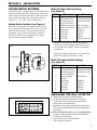
OPTION SWITCH SETTINGS
MAG bill acceptors contain an option switch bank on the
main logic board which allows the unit to be customized
to the requirements of the individual account. This switch
bank is factory set with switch 3 and 8 in the ON posi-
tion and 1, 2, 4, 5, 6, and 7 in the OFF position.
Setting Option Switches (see Figure 1)
Remove power from the bill acceptor. Remove the bill
box. Located on the side of the logic board cover is the
option switch access hole. Insert a small screwdriver
through the access hole to set the option switches as
desired (see Figure 2). Reinstall the bill box. Apply
power and test for proper operation.
Figure 2
Figure 1
MAG**SA Option Switch Settings
(see Figure 2)
MAG**B Option Switch Settings
(see Figure 2)
SWITCH ON OFF
1 High Security Standard Acceptance
2 Accepts bills in one Accepts bills in both
directions only (face directions (face up)
up, green seal first)
3 Standard credit pulse Short credit pulse
150ms on 150ms off 50 ms on 50 ms off
4 $20 Accept $20 Reject
5 $10 Accept $10 Reject
6 $5 Accept $5 Reject
7 $2 Accept $2 Reject
8 $1 Accept $1 Reject (see note)
NOTE: The 407982 logic board with software
67090 will accept $1.00 bills with Switch 8 "OFF",
if no other bills are enabled. This is the maximum
accept mode.
If however, another bill switch is "ON", then $1.00
bills will be rejected if Switch 8 is "OFF".
INSTALLING THE BILL ACCEPTOR
1. Remove power from the vending machine.
2. Set the bill acceptor option switches as desired.
3. Connect the bill acceptor harness to the mating
harness in the vending machine.
4. Mount the bill acceptor according to the instructions
found in the vending machine manual or appropriate
kit literature.
NOTE: Ensure bill acceptor is free of all obstructions
5. Load the vending machine with product and fill the
coin changer with change.
6. Apply power to the vending machine.
7. Test for proper operation.
SWITCH ON OFF
1 High Security Standard Acceptance
2 Accepts bills in one Accepts bills in both
directions only (face directions (face up)
up, green seal first)
3 Serial or Parallel Pulse Interface
Interface
4 $20 Accept $20 Reject
5 $10 Accept $10 Reject
6 $5 Accept $5 Reject
7 $2 Accept $2 Reject
8 $1 Accept $1 Reject
OPTION SWITCH
ACCESS HOLE
#8
#1
O
N
O
F
F
12345678

8
BILL RECOGNITION
When a bill is inserted into the bill acceptor and it blocks
the left and right alignment sensors as well as the center
optic sensor, the transport motor beings to run.
BILL VALIDATION
From the time the transport motor begins to run until the
trailing edge of the bill leaves the alignment sensors,
optical and magnetic sensors send information to the
microprocessor to determine the validity of the bill.
BILL STACKING AND CREDIT
If the bill is determined to be authentic, it is transported
to the stack position. Once the sensors of the lower
housings anti-pullback lever signals the microprocessor
that the bill is in the stacking position, the stacker motor
runs and credit is given.
BILL REJECTION
If the bill is determined to be invalid, the wrong denomi-
nation or the anti-pullback levers are active when the bill
is determined to be in the stack position, the transport
motor will reverse returning the bill to the customer.
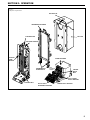
COMPONENT EXPLANATION
(see Figure 3)
Bill Transport and Stacking
The bill transport system is composed of a motor and
gearcase assembly and two sets of pulleys and belts.
When the transport motor is energized, it pulls the bill in
by sandwiching it between the lower housing rollers and
the chassis belts. During the validation process, the bill is
transferred from the lower housing rollers and chassis
belts to the intermediate frame and chassis belts.
The bill stacker is composed of a motor and gearcase
assembly and a pusher plate assembly. When the bill is
transported past the anti-pullback levers into the stacking
position, the stacker motor energizes driving the pusher
plate, which in turn, pushes the bill into the bill box.
Left and Right Alignment Sensors
The left and right alignment sensors send information to
the microprocessor to insure that the bill is the right
width and that it is being fed in correctly.
Center Optic Sensor
The center optic sensor informs the microprocessor that
the bill is ready to be transported if the information from
the alignment sensors is correct.
Left and Right Optic Sensors
The left and right optic sensors and associated circuitry
perform various optical checks on the bill and send that
information to the microprocessor for bill validation.
Magnetic Sensor
The magnetic sensor and its associated circuitry performs
checks on the magnetic properties of the bill and sends
that information to the microprocessor for bill validation.
Anti-Pullback Lever
The lower anti-pullback lever is optically monitored to
tell the microprocessor when the bill has entered the stack
position or if an attempt to defraud the unit is taking
place.
Stacker Home Sensor
The stacker home sensor is an optical sensor that informs
the microprocessor of the position of the stacker pusher
plate.
Encoder Sensor
Connected to the transport motor is an encoder wheel
which is optically monitored to determine the speed of the
transport motor and to determine the position of the bill
in the bill path.
SECTION 3: OPERATION

9
SECTION 3: OPERATION
Figure 3
Component Explanation
BILL BOX LID
INTERMEDIATE FRAME
BILL BOX
STACKER
HOME
SENSOR
PUSHER PLATE
CHASSIS BELT
ENCODER SENSOR
ANTI-
PULLBACK
LEVERS
LEFT & RIGHT
ALIGNMENT SENSORS
INTERMEDIATE
FRAME BELTS
LOWER HOUSING
CENTER OPTIC SENSOR
CENTER
DRIVE
BELT
LEFT & RIGHT
OPTIC SENSORS

10
VALIDATOR MAIN
LOGIC BOARD
407982
OR
408049
BROWN
BLACK
BLUE
2
5
6
1
2
1
2
4
3
5
5
5
5
5
5
5
5
24 AWG
24 AWG
24 AWG
24 AWG
4 PIN POWER HARNESS
(407419-1)
JONES PLUG
POWER HARNESS
(407052-1)
1
2
3
6
5
4
1
2
3
6
5
4
1
5
BLACK
RED
GREEN
WHITE
24 AWG
24 AWG
24 AWG
24 AWG
P. P. -
P. P. -
110 VAC NEU
110 VAC HOT
24 VAC HOT
24 VAC NEU
TRANSFORMER
AND HARNESS ASSEMBLY
(920949-2)
P2
P. P. -
P. P. -
110 VAC NEU
NEU INHIBIT
P. P.
HOT ENABLE
110 VAC HOT 9
8
7
6
5
4
3
P8
P7
11
11
22
22RED
BLU
WHT
WHT
P5
1
2
3
4
5
1
2
3
4
5
BRN
RED
ORG
YEL
DK GRN (W/GRN)
BLU
1
2
3
4
5
6
1
2
3
4
5
6
7
1
2
3
4
5
6
7
PUR
GRY
WHT
BLK
PNK (W/BRN/PNK)
LT BLUE (W/RD/PNK)
LT GRN (W/OR/PNK)
P3
P9
9
8
7
6
5
4
3
TO
CHANGER
CONNECTOR
(920274)
TERMINAL
PIN
(920275)
ANTI
CHEAT
GBR
WHT/GRN
WHT/BLK
WHT/RED
P14B
GBRP14A
LOWER BOARD
AND HARNESS ASSEMBLY
(407125)
P6
BLACK
BLACK
BROWN
BROWN
RED
RED
ORANGE
YELLOW
GREEN
GREEN
BLUE
PURPLE
GRAY
1
2
3
4
5
6
7
8
9
SENSOR COM
LEVER LOWER
VE3
VE2
TRANS. C
REFL. L
REFL. R
GND
+ 12V 1
2
3
4
5
6
7
8
9
BLACK
BROWN
RED
GREEN
N.C.
WHITE
N.C.
WHITE
1
2
3
4
5
6
1
2
3
4
5
6
1
2
3
4
5
6
P11
P. P.
W/RED
WHITE
2
1
24 AWG
24 AWG
MULTI-DROP BUS
CONNECTOR
(920273)
TERMINAL SOCKET
(920276)
CR-
CR+ 2
1
P1
P6
4
2
3
1
5
6
1
2
3
4
5
6
7
8
9
2
1
1
2
3
4
5
6
BRN
RED
ORG
YEL
GRN
(RED DOT)
(RED DOT)
1
2
3
4
5
33
22
11
STACKER BOARD AND
HARNESS ASSEMBLY
(407246)
STACKER
HOME
SENSOR
TRANSPORT MOTOR
(920195-2)
BLUE DOT
STACKER MOTOR
(920195)
P5 P11A P11B
ENCODER
WHEEL
UPPER BOARD
AND HARNESS ASSEMBLY
(407244)
P3
LEVER UPPER
SENSOR COM
TRANS R
TRANS L
SENSOR SINK
+12V
7
8
9
10
11
12
13
1
2
3
4
5
6
POSITION SENSOR
RIGHT SKEW
LEFT SKEW
VE3
REFL. C
ANALOG MAG
GND
CASHBOX
VE2
STACKER HOME
E.W.
+12V
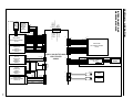
SECTION 3: OPERATION
INTERCONNECTIONS
MAG50B/MAG52B

11
SNACK VALIDATOR MAIN
LOGIC BOARD
408064
TO
CHANGER
CONNECTOR
(920274)
TERMINAL
PIN
(920275)
ANTI
CHEAT
GBR
WHT/GRN
WHT/BLK
WHT/RED
P14B
GBRP14A
LOWER BOARD
AND HARNESS ASSEMBLY
(407125)
P6
BLACK
BLACK
BROWN
BROWN
RED
RED
ORANGE
YELLOW
GREEN
GREEN
BLUE
PURPLE
GRAY
1
2
3
4
5
6
7
8
9
SENSOR COM
LEVER LOWER
VE3
VE2
TRANS. C
REFL. L
REFL. R
GND
+ 12V 1
2
3
4
5
6
7
8
9
BLACK
BROWN
BROWN
RED
GREEN
N.C.
WHITE
N.C.
WHITE
1
2
3
4
5
6
1
2
3
4
5
6
1
2
3
4
5
6
P11
P. P.
BLACK
BLUE
WHITE
4
110V POWER HARNESS
(407473)
CONNECTOR
(908834)
TERMINAL PIN
(908835-1)
MULTI-DROP BUS
CONNECTOR
(920273)
TERMINAL SOCKET
(920276)
1
2
3
6
5
4
1
2
3
6
5
4
BLACK
RED
GREEN
WHITE
24 AWG
24 AWG
24 AWG
24 AWG
P. P. -
P. P. -
110 VAC NEU
110 VAC HOT
24 VAC HOT
24 VAC NEU
TRANSFORMER
AND HARNESS ASSEMBLY
(920949-3, -2)
P2
110 VAC NEU
P. P. -
110 VAC NEU 3
2
1
P13
P6
P8
P7
11
11
22
22RED
BLU
WHT
WHT
(RED DOT)
(RED DOT)
P5
1
2
3
4
5
1
2
3
4
5
1
2
3
4
5
33
22
11
STACKER BOARD AND
HARNESS ASSEMBLY
(407246)
STACKER
HOME
SENSOR
TRANSPORT MOTOR
(920195-2)
BLUE DOT
STACKER MOTOR
(920195)
P5 P11A P11B
ENCODER
WHEEL
UPPER BOARD
AND HARNESS ASSEMBLY
(407244)
P3
BRN
RED
ORG
YEL
DK GRN (W/GRN)
BLU LEVER UPPER
SENSOR COM
TRANS R
TRANS L
SENSOR SINK
+12V
1
2
3
4
5
6
1
2
3
4
5
6
7
1
2
3
4
5
6
7
7
8
9
10
11
12
13
PUR
GRY
WHT
BLK
PNK (W/BRN/PNK)
LT BLUE (W/RD/PNK)
LT GRN (W/OR/PNK)
P3
P9
4
2
3
1
5
6
1
2
3
4
5
6
7
8
9
3
2
1
1
2
3
4
5
6
1
2
3
4
5
6
POSITION SENSOR
RIGHT SKEW
LEFT SKEW
VE3
REFL. C
ANALOG MAG
GND
BRN
RED
ORG
YEL
GRN CASHBOX
VE2
STACKER HOME
E.W.
+12V
1
2
3
4
5
6
7
8
9
24V POWER HARNESS
(407474)
CONNECTOR
(908834)
TERMINAL PIN
(908835-1)
1
2
3
4
5
6
7
8
9
1
2
3
4
5
1
2
3
4
5
P14
BROWN
BLACK
BLUE
WHITE
4
CREDIT+
ENABLE
+12V DC
GROUND
CREDIT-
P1
1
2
3
4
5
6
7
8
9
10
11
12
13
14
15
16
17
18
OUT OF SERVICE
ACCEPT ENABLE
$2 CREDIT (OUT OF SERVICE)
SEND
$1 ENABLE, LOW
$2 ENABLE, LOW
$5 ENABLE, LOW
ESCROW RETURN, LOW
$1 CREDIT
INTERRUPT
$5 CREDIT
GROUND
DATA
ESCROW RETURN HIGH
$5 ENABLE, HIGH
$2 ENABLE, HIGH
$1 ENABLE, HIGH
SECTION 3: OPERATION
INTERCONNECTIONS
MAG50SA/MAG52SA

12
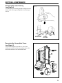
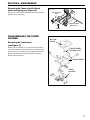
SECTION 4: MAINTENANCE
Removing the Main Logic Board
(see Figure 5)
Using a small screwdriver, release the three tabs that
secure the logic box to the main frame. Separate the
logic box from the lid by releasing the four tabs with a
small screwdriver. (Some units also have a tab that
snaps between the two harness headers.)
Unplug the harnessing from the logic board and place the
logic board in a static-free area.
DISASSEMBLING THE MAG
Removing the Bill Box (see Figure 4)
Push the bill box tab forward while sliding the bill
box up.
Figure 4
BILL BOX TAB
BILL BOX
Figure 5
LOGIC BOARD
BOX
LOCKING TABS
MAIN LOGIC BOARD
LOGIC BOX LID

13
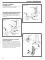
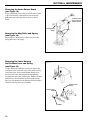
MAINFRAME LOWER
HOUSING
LOCKING
TAB
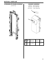
Removing the Intermediate Frame
(see Figure 7)
Using a small straight tip screwdriver, free the ten
locking tabs which secure the intermediate frame to the
main frame and remove the intermediate frame.
SECTION 4: MAINTENANCE
Removing the Lower Housing
(see Figure 6)
To remove the lower housing, push the locking tab on the
bottom of the bill acceptor and pull the lower housing to
the rear.
Figure 7
Figure 6

14
CHASSIS
HARNESS
MAIN
FRAME
CHASSIS
CHASSIS
MAIN FRAME
NUTS
STATIC GROUNDING
SPRING
SNACK
MASK
MOUNTING
FRAME
MAIN FRAME
STATIC GROUNDING
SPRING
MOUNTING
FRAME
BOTTLER
MASK
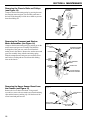
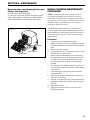
SECTION 4: MAINTENANCE
Removing the Inlet Mask
(see Figure 8 or 9)
Using a Phillips screwdriver, remove the three screws
that secure the mask to the mounting frame.
Removing the Mounting Frame and Static
Grounding Spring (see Figure 8 or 9)
Using a Phillips screwdriver, remove the screws that
attach the mounting plate and grounding spring to the
main frame.
Removing the Chassis from the Main-
frame (see Figure 10)
Remove the phillips screw securing the chassis to the
main frame. Remove the web wrap from the chassis
harness. Spread the main frame apart to release the two
locating pins of the chassis from the main frame then pull
down on the chassis. Carefully feed the chassis harness
through the opening in the main frame. Pull the chassis
out through the lower main frame opening.
Figure 8
MAG50B/MAG52B
Figure 9
MAG50SA/MAG52SA/
MAG50BAB
Figure 10

15
STACKER
BOARD
CHASSIS
ENCODER
SENSOR
SCREWDRIVER
LOCKING
TAB
LOCKING TABS
(BOTH SIDES)
SHOULDER
SCREW
TORX
HEAD
WRENCH
CABLE TIE
CHASSIS
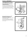
Removing the Encoder Sensor and
Stacker Board (see Figure 12)
Remove the encoder wheel dust cover from the transport
gearcase and motor assembly.
Free the encoder sensor from the top of the transport
motor gear case assembly. Remove the Phillips screw
that secures the stacker board to the chassis and remove
the stacker board.
SECTION 4: MAINTENANCE
DISASSEMBLING THE CHASSIS
Removing the Pusher Plate from the
Chassis (see Figure 11)
Cut the cable tie that secures the chassis harnessing.
Remove the two T15 Torx head shoulder screws that
secure the pusher plate to the stacker gear box assembly.
Pull the pusher plate straight out until the locking tabs of
the stacker slides catch the chassis. Using a small
screwdriver, release the four tabs and remove the pusher
plate.
Figure 11
Figure 12

16
CHASSIS BELT
PULLEY TRANSPORT GEARBOX
& MOTOR ASSEMBLY
BELT TENSIONING
SPRING
STACKER GEARBOX
& MOTOR ASSEMBLY
LOCKING TABS
LOCKING TABS
INLET
ASSEMBLY
SLOTS
STACKER
ASSEMBLY
SLOTS
CHASSIS
BELT
CHASSIS
BELT
TRANSPORT MOTOR
ASSEMBLY
Figure 15
Removing the Upper Sensor Board from
the Chassis (see Figure 15)
Remove the lower chassis belt shaft. Using a small
screwdriver, remove the two metal sensor board retaining
clips and the harness retaining clip. Lift the front of the
sensor board and pull forward.
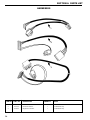
SECTION 4: MAINTENANCE
Removing the Transport and Stacker
Motor Assemblies (see Figure 14)
Compress the belt tensioning spring by pushing up on the
stacker motor and gear case assembly until the three
locking tabs of the gear case can be freed from their
mating slots in the chassis. Remove the stacker motor and
gear case assembly along with the tensioning spring.
Slide the transport motor and gear case assembly down
until its three locking tabs are freed from their mating
slots on the chassis.
Removing the Chassis Belts and Pulleys
(see Figure 13)
Compress the belt tensioning spring by pressing down on
the transport motor and gear case assembly and remove
the belts. Slide the pulleys off the lower shafts to prevent
them from falling off.
Figure 14
Figure 13
UPPER SENSOR
BOARD
SENSOR BOARD
RETAINING CLIP
HARNESS
RETAINING
CLIP
LOWER CHASSIS
BELT SHAFT

17
LOWER
HOUSING
TRANSFORMER
TRANSFORMER
HOLDING HOSE
BOTTOM
COVER
SPRING
ANTI-PULLBACK
LEVER
CENTER CHASSIS
BELT SHAFT
SECTION 4: MAINTENANCE
Removing the Chassis Anti-Pullback
Lever and Spring (see Figure 16)
Remove the center chassis belt shaft and remove the anti-
pullback lever and spring.
DISASSEMBLING THE LOWER
HOUSING
Removing the Transformer
(see Figure 17)
Remove the two Phillips screws from the bottom of the
lower housing that secure the bottom cover. Remove the
bottom cover. Cut the cable tie and separate the harness.
Remove the hose that holds the transformer in place.
Remove the transformer.
Figure 17
Figure 16

18
SECTION 4: MAINTENANCE
Removing the Mag Roller and Spring
(see Figure 18)
Remove the two Phillips screws that secure the roller
spring and remove the spring.
Removing the Lower Housing
Anti-Pullback Lever and Spring
(see Figure 19)
Using a small drift or Phillips screwdriver, depress the
locking tab in the small hole in top of the lower housing.
At the same time, insert a small standard blade screw-
driver into the center slot and push the anti-pullback
assembly back out of the retaining tabs. Remove the anti-
pullback lever from its mount by releasing the locking
tabs. Pay close attention to the placement of the spring to
assure its correct position on reassembly.
Removing the Lower Sensor Board
(see Figure 18)
Remove the Phillips screw that secures the sensor board
to the lower housing, unsnap the lower housing anti-
pullback sensor board and remove the lower sensor
board.
Figure 18
Figure 19
LOWER HOUSING
ANTI-PULLBACK
SENSOR BOARD
LOWER SENSOR
BOARD SPRING
SPRING
ANTI-PULLBACK
LEVER
ANTI-PULLBACK
MOUNT

19
FRONT PULLEY
BACK PULLEY
SHAFT
SECTION 4: MAINTENANCE
Removing the Lower Housing Rollers and
Pulleys (see Figure 20)
Slide the front pulleys off the shaft.
To remove the center belt, slide the back pulleys off the
shaft. Gently tap the back shaft with a small hammer
until the shaft splines are free from the center pulley.
MAG50 CLEANING MAINTENANCE
PROCEDURE
NOTE: Petroleum-based cleaners and freon-based
propellants can damage plastic and some electronic
components. Scouring pads and stiff brushes may harm
the protective coating on the circuit boards and can mar
the plastic. These items should never be used when
cleaning the MAG bill acceptor.
The MAG50 should be cleaned every 20,000 bills or
every two years (or as needed, depending on the environ-
mental conditions of the location). Dust can be removed
with a soft brush or cloth or it can be blown out using
compressed air.
Procedure
1. Disconnect power from the bill acceptor.
2. Remove the bill box and use a soft cloth to wipe any
dust from around the intermediate frame and stacker
plate.
3. Remove the lower housing.
4. Using compressed air or a soft brush, blow or brush
the dust off of the optic sensors.
5. Remove dust from around the rollers on the lower
housing and the sensors on the upper sensor board.
The upper sensors are located directly above the
lower housing sensors when the lower housing is
installed.
6. The bill path can be further cleaned of any dirt or oil
by using a soft cloth moistened with a mild soap and
water solution.
7. Clean the magnetic head with a cotton swab and
isopropyl alcohol.
8. Remove dust from the transport belt areas and any
other places of build up.
9. Once the lower housing is dry, place it back into the
mainframe making sure the tab on the bottom locks
into place.
10. Remount the bill box.
11. Apply power and insert bills to verify the unit is
functioning properly.
Figure 20

20
SECTION 4: MAINTENANCE
MAG50 CLEANING PROCEDURE
FOR SALT WATER POLLUTED
UNITS
NOTE: Petroleum-based cleaners and freon-based
propellants can damage plastic and some electronic
components. Scouring pads and stiff brushes may harm
the protective coating on the circuit boards and can mar
the plastic. These items should never be used when
cleaning the MAG bill acceptor.
Procedure
1. Remove power from the bill acceptor.
2. Remove the bill acceptor from the vending machine.
3. Open the bill box lid and verify that the stacker plate
is in the standby/home position. If it is not in the
home position, apply power and observe that the
stacker plate returns home.
4. Remove the bill box.
WARNING: If moisture is present, allow the unit to dry
thoroughly before applying power to avoid possible
shock hazard. If the stacker plate does not return to the
home position, remove power and carefully remove the
bill box to avoid damaging the bill box and/or stacker
plate.
5. Remove the lower housing.
6. Remove the bottom cover from the lower housing.
7. Run hot water (110°-140°F) over the lower housing
from the top and bottom. Using a soft brush, gently
clean any salt residue. Use a soft, absorbent cloth to
clean residue off the lower housing. If the trans-
former gets wet, allow the unit to dry for 24 hours
before applying power.
8. Remove the front mask. Using hot water and a soft
brush, clean the front mask, upper sensor board and
main frame anti-pullback levers.
CAUTION: The motors are not protected from water,
therefore the unit must be held in a manner that prevents
water from running over them.
9. Verify the anti-pullback levers move freely and that
the spring returns them to their extended position.
10. Allow the unit to dry thoroughly.
11. Clean the magnetic head using a swab and isopropyl
alcohol.
12. Replace the front mask.
13. Replace the lower housing cover.
14. Place the lower housing into the main frame.
15. Remount the bill box.
16. Apply power and insert bills to verify the unit is
functioning properly.
Page is loading ...
Page is loading ...
Page is loading ...
Page is loading ...
Page is loading ...
Page is loading ...
Page is loading ...
Page is loading ...
Page is loading ...
Page is loading ...
Page is loading ...
Page is loading ...
Page is loading ...
Page is loading ...
Page is loading ...
Page is loading ...
-
 1
1
-
 2
2
-
 3
3
-
 4
4
-
 5
5
-
 6
6
-
 7
7
-
 8
8
-
 9
9
-
 10
10
-
 11
11
-
 12
12
-
 13
13
-
 14
14
-
 15
15
-
 16
16
-
 17
17
-
 18
18
-
 19
19
-
 20
20
-
 21
21
-
 22
22
-
 23
23
-
 24
24
-
 25
25
-
 26
26
-
 27
27
-
 28
28
-
 29
29
-
 30
30
-
 31
31
-
 32
32
-
 33
33
-
 34
34
-
 35
35
-
 36
36


Coinco MAG SERIES Operation And Service Manual
- Type
- Operation And Service Manual
Ask a question and I''ll find the answer in the document
Finding information in a document is now easier with AI
Related papers


Other documents
-
GBA ST1 Operating instructions
-
 VENDO V21 User manual
-
 American Changer AC2207 Installation, Operation And Service Manual
-
 Crane Merchandising Systems BevMax MEDIA User manual
-
innovative technology BV50 Technical Manual
-
ICT CC6000 Installation guide
-
Maytag DN3000 User manual
-
Sentinel Unitec Owner's manual
-
 Atronic GPT ARGUS B User manual
-
 Alberici BILLYONE UN1 User manual


