Page is loading ...

Copyright Innovative Technology Ltd 2014 GA717-3
Innovative Technology assume no responsibility for errors, omissions, or damages
resulting from the use of information contained within this manual.
BV50
OPERATIONS
MANUAL

1
Copyright Innovative Technology Ltd 2014 GA717-3
BV100 Operations Manual
Contents
1 INTRODUCTION ................................................................................................................................................... 2
2 ENVIRONMENT AND POWER REQUIREMENTS ................................................................................................. 3
3 GENERAL DESCRIPTION ..................................................................................................................................... 4
4 MACHINE INTERFACES ....................................................................................................................................... 6
4.1 BEZEL LED’s ................................................................................................................................................ 6
4.2 HARDWARE .................................................................................................................................................. 6
4.2.1 POINTS AND BUTTONS ........................................................................................................................ 6
4.2.2 INTERFACE PIN DETAILS...................................................................................................................... 6
4.2.3 CONFIGURATION BUTTON FUNCTIONS ............................................................................................... 7
4.2.4 HARDWARE OPTIONS .......................................................................................................................... 8
4.3 PROTOCOLS ................................................................................................................................................. 8
4.3.1 SMILEY
®
SECURE PROTOCOL (SSP) ................................................................................................... 8
4.3.2 ccTALK
®
................................................................................................................................................ 9
4.3.3 MDB (Multi Drop Bus) ....................................................................................................................... 10
4.3.4 PARALLEL .......................................................................................................................................... 11
4.3.5 PULSE ................................................................................................................................................ 12
4.3.6 BINARY .............................................................................................................................................. 13
4.3.7 NON-ISOLATED SERIALPROTOCOL (NIS) ......................................................................................... 13
5 RE-PROGRAMMING THE BV50 ....................................................................................................................... 14
5.1 BV50 CONFIGURATION VARDS ................................................................................................................ 14
5.2 BANKNOTE VALIDATOR CURRENCY MANAGER SOFTWARE .................................................................. 14
5.3 VALIDATOR PROGRAMMING SYSTEM (DA3)........................................................................................... 15
6 LOW POWER OPTION ....................................................................................................................................... 16
7 MAINTENANCE AND RE-INITIALISATION ......................................................................................................... 17
7.1 ROUTINE MAINTENANCE ......................................................................................................................... 17
7.2 RE-INITIALISATION .................................................................................................................................... 17
8 DIAGNOSTICS................................................................................................................................................... 18
9 SUPPORT .......................................................................................................................................................... 19
9.1 CONFIGURATION CARDS .......................................................................................................................... 19
9.2 VALIDTOR PROGRAMMING SYSTEMS (DA3) .......................................................................................... 19
9.3 INTERNET WEB SUPPORT ........................................................................................................................ 19
9.4 EMAIL SUPPORT ....................................................................................................................................... 19
10 APPENDIX ...................................................................................................................................................... 20
10.1 APPENDIX A – BV50 ORDER FORM ...................................................................................................... 20
10.2 APPENDIX B – DIMENSION DRAWING .................................................................................................. 21
10.3 APPENDIX C – CASHBOX INFORMATION .............................................................................................. 22
10.4 APPENDIX D – CONFIGURATION CARDS............................................................................................... 22
10.5 APPENDIX E – ESCROW FUNCTION ...................................................................................................... 24
10.6 APPENDIX F - IMPLEMENTED ccTALK COMMANDS ............................................................................. 25

2
Copyright Innovative Technology Ltd 2014 GA717-3
BV100 Operations Manual
1 INTRODUCTION
This manual describes the operation of the BV50 Bill Acceptor programmed with Firmware Version 4.04 or
greater.
CAUTIONS:
• THIS PRODUCT MUST BE FITTED WITH A 2 AMP TIME DELAY FUSE BEFORE USE.
• DUE TO DIFFERENT BILL CYCLE TIMES THERE MAY BE TIMING DIFFERENCES FROM THE NV PRODUCTS.
We recommend that you study this manual as there are many new features permitting new uses and more
secure applications.
If you do not understand any part of this manual please contact your local office for assistance, contact
details are available from www.bellis-technology.com. In this way we may continue to improve our product.
WARNING
ONLY SUITABLY TRAINED PERSONNEL SHOULD CARRY OUT ANY WORK ON THIS EQUIPMENT IN
ACCORDANCE WITH ALL CURRENT LOCAL, NATIONAL AND INTERNATIONAL HEALTH AND SAFETY
REGULATIONS.
MAIN HEADQUARTERS
Innovative Technology Ltd
Derker Street – Oldham – England - OL1 4EQ
Tel: +44 161 626 9999 Fax: +44 161 620 2090
E-mail: [email protected]
Web site: www.innovative-technology.co.uk
AUSTRALIA
support@innovative-technology.com.au
BRAZIL
suporte@bellis-technology.com.br
CHINA
support@innovative-technology.co.uk
GERMANY
supportDE@innovative-technology.eu
ITALY
supportIT@innovative-technology.eu
SPAIN
supportES@innovative-technology.eu
UNITED KINGDOM
support@innovative-technology.co.uk
REST OF THE WORLD
support@innovative-technology.co.uk

3
Copyright Innovative Technology Ltd 2014 GA717-3
BV100 Operations Manual
2 ENVIRONMENT AND POWER REQUIREMENTS
ENVIRONMENT
POWER REQUIREMENTS
Table 2 – Power Requirements
Table 3 – Interface Logic Levels
Environment
Minimum
Maximum
Temperature
+3ºC (37F)
+50ºC (122F)
Humidity
5%
95% Non condensing
Table 1 – Environmental Requirements
Electrical Supply
Minimum
Maximum
Supply Voltage (V DC) Absolute
Limits
+11 V
+13.5 V
Supply Ripple Voltage
0 V
0.25 V @ 100 Hz
Supply Currents:
Sleep (low power mode)
TBC
Standby
0.4 A
Validating
1.5 A
Peak (Motor Stall)
3.0 A
Interface Logic Levels
Logic Low
Logic High
Inputs
0 V to + 0.5 V
+3.7 V + 12 V
Outputs with 2K2 pull up
0.6 V
Pull up voltage of host interface
Maximum Current Sink
50mA per output

4
Copyright Innovative Technology Ltd 2014 GA717-3
BV100 Operations Manual
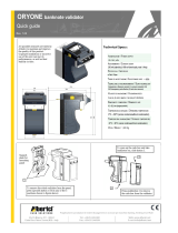
3 GENERAL DESCRIPTION
The BV50 Bill Acceptor is a compact bill-validating machine suitable for
most money machines. It will accept up to 16 different denominations of
bills in the serial control mode. The BV50 is designed for easy installation
in most machines with a choice of interface protocols as described in
chapter 4.3 - Protocols.
Figure 1 - The BV50 bill acceptor
Currency
The BV50 Bill Acceptor leaves the factory pre-set to at least one currency so that it is ready for immediate
installation. If it is required to change the currency dataset this may be done using the PC based Validator
Management software or with the DA3 Validator Programming System, see chapter 5 - Reprogramming the
BV50 for more details.
New currencies and applications are being tested all the time, please refer to our web site or contact your
local office for information concerning specific currencies if they are not already included on our approved
list.
Cash Box
Various size cash boxes are available for the BV50. The standard cash box will hold approximately 300
bills. Cash box spacers can be added at the factory to increase the capacity. Each spacer will add an extra
200 note capacity with a maximum of 3 spacers. This gives a maximum capacity of approximately 900
bills. (see Appendix C – Cash Box Information for more details).
The Required cash box capacity must be stated at the time of ordering. If no capacity is specified, the
standard cashbox will be delivered.
Note: cash box spacers can only be added at our factory, and once fitted cannot be removed.
Mounting
The BV50 is designed to easily mount onto existing mounting studs in many OEM machines. See drawing
number GA800 in Appendix B – Dimension Drawings for location and dimensions of the mounting lugs.
Disconnect all power to the machine and mount the BV50 onto the mounting studs. Connect the interface
cable from the machine to the BV50 and apply power to the machine.
Different harnesses are available depending on the required mode of operation (see chapter 4.2.4 -
Hardware Options).
Bill sizes accepted
Width: 66mm, Length: 156mm
Weight
0.85kg
Bill to bill time
3 seconds
Escrow
Single bill
Cash box capacity
300 used bills for standard cash box.
Up to a maximum capacity of 900 bills.
Interface
SSP, Parallel, Pulse, Binary, ccTalk, MDB.
(Contact ITL for other interface availability)

5
Copyright Innovative Technology Ltd 2014 GA717-3
BV100 Operations Manual
ORDERING INFORMATION
BV50
USD01
404
CCT
300
123456
Product
Dataset
Firmware
Version
Firmware
Interface
Cashbox
Capacity
CcTalk
Encryption
Key
Figure 2 - Order Code Example
Dataset – This code signifies the currency and bills included. For available datasets and dataset codes,
please refer to the currency download section of our website
www.bellis-technology.com.
Firmware – This code is the version of firmware required. If left blank, the latest current version will be
programmed
Interface – This is the 3 letter code of the required communications interface. For more details of available
interfaces, see chapter 4.3 - Protocols.
SSP – Smiley Secure Protocol
MDB – Multi-Drop-Bus (MDB in-line module required)
PL1 – Pulse Mode 1
SP4 – Special Pulse (always enabled)
CCT – ccTalk
PAR – Parallel
BIN – Binary
Cashbox Capacity – The required capacity of the cashbox. Sizes available are 300, 500, 700 or 900.
ccTalk Encryption Key – The required ccTalk encryption key if the selected interface is CCT. If left blank, a
key of 123456 will be used.

6
Copyright Innovative Technology Ltd 2014 GA717-3
BV100 Operations Manual
16
15
1
2
4 MACHINE INTERFACES
4.1 BEZEL LED’s
The Bezel LED’s are used to indicate a variety of status signals as described below in Table 5 - Bezel LED
Diagnostic Codes.
4.2 HARDWARE
4.2.1 POINTS AND BUTTONS
4.2.2 INTERFACE PIN DETAILS
The function of pins 1-8 changes according to which machine interface is being used. See the individual
interface descriptions for details.
Figure 3 – BV50 Cable connections
Number of
LONG flashes
Number of SHORT flashes
1
2
3
4
1
Note Path Open
Note Path Jam
Unit Not
Initialized
2
Cash Box
removed
Cash Box Jam
3
Firmware
Checksum
Interface
checksum
EEPROM
Checksum
Dataset
Checksum
4
PSU too Low
PSU too High

7
Copyright Innovative Technology Ltd 2014 GA717-3
BV100 Operations Manual
Pin
Name
Type
Description
1
Vend 1
Output
Open collector outputs. Function changes
depending on machine interface protocol (see
individual interface descriptions for details)
2
Vend 2
Output
3
Vend 3
Output
4
Vend 4
Output
5
Inhibit 1
Input
Inputs are held high to internal +5V via 10KΩ.
Function changes depending on machine interface
protocol (see individual interface descriptions for
details)
6
Inhibit 2
Input
7
Inhibit 3
Input
8
Inhibit 4
Input
9
Busy
Output
Active LOW when the BV50 is transporting, reading
or stacking a note
10
Escrow
Input
Enable the escrow function by holding LOW in
Parallel, Pulse or Binary modes (See Appendix E –
Escrow Function)
11
-
-
Do not connect
12
-
-
Do not connect
13
Factory Use Only
Do not connect
14
Factory Use Only
Do not connect
15
+Vin
Power
Nominal 12V DC supply
16
0V
Ground
0V supply
Table 6 – 16 way External Connector Pin Out
4.2.3 CONFIGURATION BUTTON FUNCTIONS
The functions available via the Configuration Function Button are detailed in Table 7 - Configuration
Button Functions.
Table 7 – Configuration Button Functions
Configuration Button
Power Status
Function
Press & Hold (>2 secs)
Powered ON
Sets BV50 to Programming
Mode (SSP)
Press Once (<1 sec)
Powered ON
Enables Configuration Card
Programming
Press twice (within half a second)
Powered ON
Current Setting Indicator
Press & Hold (as power is applied)
Powered OFF → ON
Resets ccTalk key to Default
setting

8
Copyright Innovative Technology Ltd 2014 GA717-3
BV100 Operations Manual
BV50 Programming Mode
Press and Hold the Configuration Button for at least 2 seconds while the BV50 is powered up. The Bezel
LED will flash rapidly to indicate that the SSP interface is being loaded. Once this process has finished the
BV50 will reset. The BV50 will now be in Programming Mode (SSP) and allow connection to a PC via a DA1
or DA2 adapter or connection to a DA3.
Note: This mode can only be cancelled by re-programming with a Configuration Card or via the Validator
Manager program. Please ensure you are aware of all the BV50 programmed settings before entering this
mode. Failure to restore the original setting will stop the BV50 from operating in the host machine.
Configuration Card Programming Mode
Press the Configuration Button once while the BV50 is powered up. If done correctly the Bezel LED will
flash every 1-second. This will allow the insertion of a Configuration Card to change the Firmware Protocol
in the BV50. (See chapter 5.1 - BV50 Configuration Card for full details). This mode can be cancelled by
again pressing the Configuration Button once.
Current Setting Indicator Mode
Press the Configuration Button twice within half a second while the BV50 is powered up. The BV50 Bezel
LED will then perform a series of flashes to indicate the current settings within the bill acceptor. (See
Program Check Procedure section of Appendix D – Configuration Cards for details on decoding the flashes)
Encryption Key Reset Function (ccTalk)
Note: This function will only be possible if the BV50 is programmed to ccTalk mode. It is not possible to
reset the key from SSP mode.
Press and hold the Configuration Button while the BV50 powered is off. Apply the power and keep the
button pressed for several seconds. The ccTalk Encryption key will now be restored to the default setting..
4.2.4 HARDWARE OPTIONS
The BV50 can be used in machines with a 110V supply or an MDB machine with the addition of in-line
modules. The in-line modules connect between the BV50 16-pin connector and the host machine. It is
essential that the correct interface is programmed in the BV50 for the bill acceptor to operate correctly For
the 110V option, the SP4 firmware interface must be programmed if the bill acceptor is to be always
enabled. For the MDB option, the MDB Firmware option must be programmed. For more information on
selecting the interface, see chapter 5 - Reprogramming the BV50.
4.3 PROTOCOLS
4.3.1 SMILEY
®
SECURE PROTOCOL (SSP)
SSP is a secure serial interface specifically designed to address the problems experienced by cash
handling systems in gaming machines. Problems such as acceptor swapping, reprogramming acceptors
and line tapping are all addressed. This interface is recommended for all new designs. The interface uses a
master slave model, the host machine is the master and the peripherals (bill acceptor, coin acceptor or
coin hopper) are the slaves. Data transfer is over a multi-drop bus using clock asynchronous serial
transmission with simple open collector drivers. The integrity of data transfers is ensured through the use
of 16 bit CRC checksums on all packets.
BV50 Connections
16
15
1
2

9
Copyright Innovative Technology Ltd 2014 GA717-3
BV100 Operations Manual
Pin
Name
Type
Description
1
Vend 1
Output
Serial Data Out (Tx)
2
Vend 2
Output
Not Used
3
Vend 3
Output
Not Used
4
Vend 4
Output
Not Used
5
Inhibit 1
Input
Serial Data In (Rx)
6
Inhibit 2
Input
Not Used
7
Inhibit 3
Input
Not Used
8
Inhibit 4
Input
Not Used
9
Busy
Output
Not Used
10
Escrow
Input
Not Used
11
-
-
Do not connect
12
-
-
Do not connect
13
Factory Use Only
Do not connect
14
Factory Use Only
Do not connect
15
+Vin
Power
Nominal 12V DC supply
16
0V
Ground
0V supply
Table 8 - SSP Pin Description
Other information:
Minimum time between Polls: - 200ms
Default SSP address: - 0x00
For detailed information and full protocol specification please refer to SSP Interface Specification ITL
(Drawing GA138), this is available from the Bellis Technology website www.bellis-technology.com.
To help in the software implementation of the SSP, ITL can provide DLL controls and Visual Basic
applications on request. Please contact supportusa@bellis-technology.com for more information.
4.3.2 ccTALK
®
ccTalk® is a serial communication protocol commonly used in gaming machines. The protocol allows
various types of cash handling equipment to be connected to the same 3-wire bus (+12V, 0V and Data). To
use the BV50 in ccTalk mode, pins 1 and 5 (Tx and Rx) must be connected together as the data line.
BV50 Connections
1
2
16
15
5
Data
+12V
0V

10
Copyright Innovative Technology Ltd 2014 GA717-3
BV100 Operations Manual
Connections:
Pin
Name
Type
Description
1
Vend 1
Output
Serial Data. Must also be connected to pin 5
2
Vend 2
Output
Not Used
3
Vend 3
Output
Not Used
4
Vend 4
Output
Not Used
5
Inhibit 1
Input
Serial Data. Must also be connected to pin 1
6
Inhibit 2
Input
Not Used
7
Inhibit 3
Input
Not Used
8
Inhibit 4
Input
Not Used
9
Busy
Output
Not Used
10
Escrow
Input
Not Used
11
-
-
Do not connect
12
-
-
Do not connect
13
Factory Use Only
Do not connect
14
Factory Use Only
Do not connect
15
+Vin
Power
Nominal 12V DC supply
16
0V
Ground
0V supply
Table 9 - ccTalk Pin Description
Other Information:
For a list of supported commands please see Appendix F – Implemented ccTalk Commands
For detailed information and full protocol specification, please refer to www.cctalk.org
Default ccTalk address: - 0x28 (40 dec)
Encrypted ccTalk uses 16 bit CRC checksum. If the encryption is disabled, the user can select either simple
8 bit or 16 bit CRC checksums.
4.3.3 MDB (Multi Drop Bus)
MDB is a serial bus interface commonly used in electrically controlled vending machines. This is a 9600
Baud Master-Slave system where the BV50 Bill Acceptor is a slave to a master controller. A Vending
Machine Controller (VMC) has the capability of communicating with 32 peripherals or slaves.
BV50 Connections:
To use the BV50 in MDB mode, an MDB in-line module is required. The in-line module regulates the power
supply and opto-isolates the communication lines.
Other Information:
MDB address: - 0x30
The BV50 supports the MDB Protocol Version 1, Level 1.
For detailed information and full protocol specification, please refer to www.vending.org.

11
Copyright Innovative Technology Ltd 2014 GA717-3
BV100 Operations Manual
1
2
16
15
4.3.4 PARALLEL
In parallel mode the BV50 will issue a 100ms (±3%) active LOW pulse on the relevant vend line. A
maximum of 4 channels can be used.
BV50 Connections:
Pin
Name
Type
Description
1
Vend 1
Output
Channel 1 credit, 100ms (±3%) active LOW pulse.
2
Vend 2
Output
Channel 2 credit, 100ms (±3%) active LOW pulse.
3
Vend 3
Output
Channel 3 credit, 100ms (±3%) active LOW pulse.
4
Vend 4
Output
Channel 4 credit, 100ms (±3%) active LOW pulse
5
Inhibit
1
Input
Inhibit channel 1 by holding this pin HIGH, hold LOW to
enable.
6
Inhibit
2
Input
Inhibit channel 2 by holding this pin HIGH, hold LOW to
enable.
7
Inhibit
3
Input
Inhibit channel 3 by holding this pin HIGH, hold LOW to
enable.
8
Inhibit
4
Input
Inhibit channel 4 by holding this pin HIGH, hold LOW to
enable.
9
Busy
Output
Active LOW when the NV200 is transporting, reading or
stacking a note
10
Escrow
Input
Enable the escrow function by holding LOW (See
APPENDIX E – ESCROW FUNCTION)
11
-
-
Do not connect
12
-
-
Do not connect
13
Factory Use Only
Do not connect
14
Factory Use Only
Do not connect
15
+Vin
Power
Nominal 12V DC supply
16
0V
Ground
0V supply
Table 10 - Parallel and Binary Pin Description
Vend Signals: Pins 1-4. Each of the four channels have their own individual output. If a bill is recognized
and stacked then the relevant vend line is set low for a period of 100ms ±3%. Pulses outside these limits
should be rejected as a precaution against false triggering.
Inhibit Inputs: Pins 5-8. Channels 1 to 4 have their own inhibit input to allow the host machine to refuse
specified bills. To inhibit a channel, the relevant inhibit input must be held high. To enable a channel, the
corresponding inhibit must be latched low so that bills may be accepted.
If all four inhibits are high simultaneously then the BV50 will be disabled. In this state the bezel will not
illuminate and if a bill is inserted the motor will run in reverse preventing the insertion of the bill.
All four inhibits may be connected together to create a 'global' inhibit. In this way the BV50 may be brought
in and out of operation by the host machine.
Busy Output: Pin 9. This is a general-purpose busy signal. It is active low while the BV50 is in operation.
Escrow Control: Pin 10. Hold this pin Low to enable the single bill escrow function. (See Appendix E –
Escrow Function).

12
Copyright Innovative Technology Ltd 2014 GA717-3
BV100 Operations Manual
1
2
16
15
4.3.5 PULSE
In Pulse mode the BV50 outputs a number of pulses on Vend 1. The number of pulses for
each channel is different and set to default values within the dataset. The number of pulses and duration
can be modified using the Validator Manager software. Also a pulse multiplier and the pulse duration can
be modified using a configuration card.
A maximum of 16 channels can be used in Pulse mode.
BV50 Connections:
Pin
Name
Type
Description
1
Vend 1
Output
Credit pulse stream output
2
Vend 2
Output
Not used
3
Vend 3
Output
Not used
4
Vend 4
Output
Not used
5
Inhibit
1
Input
Inhibit channel 1 by holding this pin HIGH, hold LOW to
enable
6
Inhibit
2
Input
Inhibit channel 2 by holding this pin HIGH, hold LOW to
enable
7
Inhibit
3
Input
Inhibit channel 3 by holding this pin HIGH, hold LOW to
enable
8
Inhibit
4
Input
Inhibit channel 4 by holding this pin HIGH, hold LOW to
enable
9
Busy
Output
Active LOW when the BV50 is transporting, reading or
stacking a note
10
Escrow
Input
Enable the ESCROW function by holding LOW
11
-
-
Do not connect
12
-
-
Do not connect
13
Factory Use Only
Do not connect
14
Factory Use Only
Do not connect
15
+Vin
Power
Nominal 12V DC supply
16
0V
Ground
0V supply
Table 11 - Pulse Mode Pin Description
NOTES:
• Channels higher than 4 cannot be individually inhibited, but will be globally inhibited if inhibits 1 to 4 are
inhibited simultaneously.
• When using the 110V PSU in-line module, the Special Pulse interface (SP4) must be used. This operates
the same as the standard pulse mode but the bill acceptor is always enabled whatever the state of the
inhibit lines.
• Red Wire: 12V DC power supply (min.1.5 amp) DC only.
• Black Wire: Ground Power Supply.
• Green Wire: Credit pulse (active low) to board or coin switch.

13
Copyright Innovative Technology Ltd 2014 GA717-3
BV100 Operations Manual
4.3.6 BINARY
In Binary mode, the BV50 will issue a binary pattern on vend lines 1 to as shown in Table 12 - Binary Credit
Outputs. A maximum of 15 channels can be used.
Vend
1
Vend
2
Vend
3
Vend
4
Credit
Channel
LOW
HIGH
HIGH
HIGH
Channel1
HIGH
LOW
HIGH
HIGH
Channel 2
LOW
LOW
HIGH
HIGH
Channel 3
HIGH
HIGH
LOW
HIGH
Channel 4
LOW
HIGH
LOW
HIGH
Channel 5
HIGH
LOW
LOW
HIGH
Channel 6
LOW
LOW
LOW
HIGH
Channel 7
HIGH
HIGH
HIGH
LOW
Channel 8
LOW
HIGH
HIGH
LOW
Channel 9
HIGH
LOW
HIGH
LOW
Channel 10
LOW
LOW
HIGH
LOW
Channel 11
HIGH
HIGH
LOW
LOW
Channel 12
LOW
HIGH
LOW
LOW
Channel 13
HIGH
LOW
LOW
LOW
Channel 14
LOW
LOW
LOW
LOW
Channel 15
Table 12 - Binary Credit Outputs
Connections: Connections in Binary mode are the same as for Parallel mode described in Table 10 -
Parallel and Binary Pin Description
NOTE: Channels higher than 4 cannot be individually inhibited, but will be globally inhibited if inhibits 1 to 4
are inhibited simultaneously.
4.3.7 NON-ISOLATED SERIALPROTOCOL (NIS)
To use NIS mode the NIS option of the interface firmware must be loaded into the BV50. This is available
within the IF_02 download file.
There is a single output DATA line from the BV50 and three control lines: two from the controller ‘’ACCEPT
ENABLE’’ and ‘’SEND’’ and one from the bill acceptors IRQ (INTERRUPT) (see table 13).
For further details on this protocol please refer to the series 2000 interface manual (reference number
20105-002850046-PS), or contact supportusa@bellis-technology.com
Connection Details:
Signal
BV50 (Harness Wire Color)
+12V
15 (Red)
0V
16 (Black)
ACCEPT ENABLE
6 (Yellow)
SEND
7 (Brown)
IRQ (INTERRUPT)
2 (White)
DATA
1 (Orange)
OUT_OF_SERVICE
3 (Blue)
Table 13- Extended Interface USA Serial

14
Copyright Innovative Technology Ltd 2014 GA717-3
BV100 Operations Manual
5 RE-PROGRAMMING THE BV50
5.1 BV50 CONFIGURATION VARDS
The Configuration Cards offer the following functions:
• Select required Communication Interface (SSP, Pulse, Parallel etc).
•Adjust the channel and pulse configuration on a pre-programmed BV50 to your own requirements.
The Configuration Card Programming Function of the BV50 is enabled by pressing the ‘Configuration
Button’ on the right hand side of the BV50 (see Chapter 4.2.1 - Ports and Buttons for the button location).
For details on how to complete the configuration cards please see Appendix D – Configuration Cards
1. Press the Configuration button once (<1second) while the bill acceptor is powered up.
2. The bezel LED’s will now flash with a steady heartbeat until a Configuration Card is entered.
3. Once the Configuration Card has been entered the bill acceptor reads the card and immediately returns
it.
4. The LEDs then flash rapidly while the interface is being changed. If the LEDs flash a number of times
slowly, it is an indication of an error (For details of the Error Flash codes please see Appendix D –
Configuration Cards
5. When the changes are complete the bill acceptor resets.
If a configuration card is not entered, this function can be cancelled by pressing the button again once. It
is now possible to check the programmed settings of the BV50 by pressing the Configuration button twice
quickly (double click). For details see Appendix D – Configuration Cards.
5.2 BANKNOTE VALIDATOR CURRENCY MANAGER SOFTWARE
The ITL BNV Currency Manager software offers the following functions:
• Adjust the channel and pulse configuration on a pre-programmed BV50 to your own requirements.
• Select required Communication Interface (SSP, ccTalk, Parallel etc).
• Program the bill acceptor by downloading pre-prepared download files via the DA1 or DA2 kit.
• Check the firmware version and currency set already loaded on a BV50 unit.
• Download an updated version of firmware onto the BV50.
• Use diagnostic functions to check bill acceptors operation
The BV50 is connected to either the serial port of a PC using a DA1 kit, or the USB port using a DA2 kit and
set to programming mode using the configuration.
1. Press and hold the Configuration button (>2 seconds) while the bill acceptor is powered up.
2. The bezel LED’s will illuminate. Release the configuration button. The Bezel LED’s will flash rapidly as
the SSP interface is being programmed
3. Use the ITL Bank Note Validator Currency Manager Software and select ‘set validator options’ from the
‘tools’ menu
4. The interface and other configurations can be altered to the desired settings
5. Click the apply changes button on the ‘update changes’ tab to download the new settings to the
acceptor.
Notes:
• The Bill acceptor must be set to Programming Mode (SSP) when connected to a computer or DA3 (See
Chapter 4.2.3 - Configuration Button Functions).
• The programming mode can only be cancelled by re-programming with a Configuration Card or via the
Validator Manager program. Please ensure you are aware of all the BV50 programmed settings before
entering this mode. Failure to restore the original setting will stop the BV50 from operating in the host
machine.
•ITL BNV Currency Manager 3.2.2 or higher must be used to access the BV50 functions.

15
Copyright Innovative Technology Ltd 2014 GA717-3
BV100 Operations Manual
5.3 VALIDATOR PROGRAMMING SYSTEM (DA3)
The DA3 is a programming system designed to enable the programming of ITL Bill Acceptors in the field
without the use of a PC.
Once the DA3 has been programmed the user can:
• Update the existing software within a bill acceptor to the latest versions using the BNV Match
Download function.
• Reprogram the bill acceptor to accept a different currency using the BNV Override Download function
• Test the functionality of the bill acceptor away from the host machine.
For full DA3 operation and functionality details please refer to the DA3 User Manual (Document number
GA339).
When programming a BV50 using the DA3 BNV Override Download function, the firmware interface is
unchanged. A Configuration Card must be used after re-programming if a different interface is required.

16
Copyright Innovative Technology Ltd 2014 GA717-3
BV100 Operations Manual
6 LOW POWER OPTION
Low power Mode can be used with all none serial communication protocols to reduce the power
consumption of the BV50 when idle in Parallel, Pulse and Binary Interfaces.
The BV50 goes into low power mode approximately 6 seconds after the bill acceptor is powered up and
remains in this state until a bill is entered (Time A). Following a bill insertion the BV50 returns to Low Power
mode approximately 1 second after the Busy line goes High (Time B).
NOTE:
• Low Power Mode can ONLY be used with Parallel, Pulse and Binary protocols
• Low power mode can only be enabled by correctly completing the configuration cards or via the ITL BNV
Currency Manager software
• In low power mode the front sensor is checked every 1 second which can lead to a delay in accepting the
bill when it is presented
• Configuration button functions are only available during power up before the BV50 goes into low power
mode.
Table 14 - Electrical Supply Specification
Figure 4 – Low Power Mode Timing Diagram
Electrical Supply
Minimum
Maximum
Supply Voltage (Absolute
Limits)
+11 V
+13.5 V
Supply Ripple Voltage
0 V
0.25 V @ 100 Hz
Supply Currents:
Sleep (low power mode)
TBC
Standby
0.4 A
Validating
1.5 A
Peak (Motor Stall)
3.0 A

17
Copyright Innovative Technology Ltd 2014 GA717-3
BV100 Operations Manual
7 MAINTENANCE AND RE-INITIALISATION
7.1 ROUTINE MAINTENANCE
The BV50 Bill Acceptor has been designed to minimise any performance variation over time. Much of this
is achieved by careful hardware and software design. However, depending upon the environment the BV50
may at some time require cleaning.
CAUTION: Do not use solvent based cleaners such as alcohol, petrol, methylated spirits, white spirit or pcb
cleaner. This will result in permanent damage to the bill acceptor, only use a mild detergent.
To clean, push down the latch plates on the side of the bill acceptor, and allow the stacker/cashbox
assembly to lower. The note path is now exposed for cleaning. Carefully wipe the surfaces with a soft lint
free cloth that has been dampened with a water and mild detergent solution (i.e. household washing up
liquid). Ensure the note path is clean and dry before closing the unit and inserting bills.
7.2 RE-INITIALISATION
The BV50 has an in-built self-calibration system that maintains the optical sensors at their best operating
point. However if the BV50 is disassembled for any reason it will need to be re-initialized. Re-initialization
may only be performed under license from ITL, contact support@innovative-technology.co.uk for further
details. Re-initialization can only be performed in conjunction with the diagnostics function within the Bank
Note Validator Currency Manager.

18
Copyright Innovative Technology Ltd 2014 GA717-3
BV100 Operations Manual
8 DIAGNOSTICS
Symptom
Possible Cause
Corrective Action
All Bills are rejected
(Bezel LED’s are on)
Incorrect currency file
programmed
Check that the required dataset
is programmed in to the bill
acceptor using the validator
manager software
Bills are not included in the
currency file
Check that the required
denomination and issue are
included in the currency file using
the validator manager software
Bills are inhibited by the
host machine
Ensure the machine is ready to
accept bills. If a coin hopper is in
the machine ensure it is not
empty. Ensure the maximum
allowed credit on the host
machine has not been exceeded.
Bills are not taken in (no
bezel LED’s)
No Power
Ensure the correct specification
power is applied to the bill
acceptor.
Incorrect interface is
programmed
Check which interface is
programmed into the bill
acceptor by double clicking the
configuration button. The
displayed code indicates which
interface is programmed as
described in Appendix D –
Configuration Cards: Program
Check Procedure.
Bills stacked but no
credit given
Incorrect interface is
programmed
Check which interface is
programmed into the bill
acceptor by double clicking the
configuration button. The
displayed code indicates which
interface is programmed as
described in Appendix D –
Configuration Cards: Program
Check Procedure.
Rear bill detect sensor
obscured
Remove the cash box and ensure
no foreign objects are obstructing
the sensors
Bezel LED’s are flashing
See 4.1 for details of LED
Status signals
Motor continues to run
Foreign object or bill is
stuck in the note path
Ensure the note path is clear and
reset the bill acceptor. It may also
be necessary to reset the host
machine.

19
Copyright Innovative Technology Ltd 2014 GA717-3
BV100 Operations Manual
9 SUPPORT
The following support tools are available for use with the BV50 Bill Acceptor:
- Configuration Cards.
- ITL Bank Note Validator Currency Manager Software.
- Validator Programming System (DA3)
- Downloads from the Bellis Technology website: www.belis-technology.com
- E-mail Support via supportusa@bellis-technology.com
9.1 CONFIGURATION CARDS
For full details of the use and function of the Configuration Cards please see Appendix D – Configuration
Cards.
9.2 VALIDTOR PROGRAMMING SYSTEMS (DA3)
For full details of the use and function of the Validator Programming System and DA3, see chapter 5.3 -
Validator Programming System (DA3) and the DA3 User Manual (Document number GA339).
9.3 INTERNET WEB SUPPORT
The Bellis Technology website provides the means to download new and updated currency sets and new
versions of firmware for the BV50. You can obtain these along with technical bulletins by visiting
www.bellis-technology.com.
9.4 EMAIL SUPPORT
If the data you require is not available over the Internet Bellis Technology supports an e-mail system to
help customers with unusual requirements. The address is: s[email protected]om.
/