Page is loading ...

EVCO S.p.A. | EVJH95 | Instruction sheet ver. 1.1 | Code 104JH95E113 | Page 1 of 3 | PT 17/23
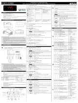
EVJH95 Controller for DHW heat pump heaters
EN
ENGLISH
- power supply 115... 230 VAC
- DHW tank upper and lower probe, evaporator probe (PTC/NTC/Pt 1000)
- photovoltaic, HP and multi-purpose digital input (see i0)
- compressor relay 16 A res. @ 250 VAC
- alarm buzzer
- TTL MODBUS slave port for EVconnect app, EPoCA remote monitoring system or for
BMS.
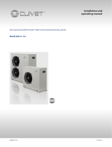
1 MEASUREMENTS AND INSTALLATION
Measurements in mm (inches). Front installation on a plastic or metal panel (with elastic
holding flaps).
N.B.
The thickness of a metal panel must be between 0.8 and 1.5 mm (1/32 and 1/16 in),
while that for a plastic panel must be between 0.8 and 3.4 mm (1/32 and 1/8 in).
INSTALLATION PRECAUTIONS
-Ensure that the working conditions are within the limits stated in the TECHNICAL
SPECIFICATIONS section.
-Do not install the device close to heat sources, equipment with a strong magnetic field,
in places subject to direct sunlight, rain, damp, excessive dust, mechanical vibrations
or shocks.
-In compliance with safety regulations, the device must be installed properly to ensure
adequate protection from contact with electrical parts. All protective parts must be
fixed in such a way as to need the aid of a tool to remove them.
2 ELECTRICAL CONNECTION
N.B.
-Use cables of an adequate section for the current running through them.
-To reduce any electromagnetic interference connect the power cables as far away
as possible from the signal cables.
PRECAUTIONS FOR ELECTRICAL CONNECTION
-If using an electrical or pneumatic screwdriver, adjust the tightening torque.
-If the device has been moved from a cold to a warm place, the humidity may have
caused condensation to form inside. Wait about an hour before switching on the
power.
-Make sure that the supply voltage, electrical frequency and power are within the set
limits. See the section TECHNICAL SPECIFICATIONS.
-Disconnect the power supply before doing any type of maintenance.
-Do not use the device as safety device.
-For repairs and for further information, contact the EVCO sales network.
3 FIRST-TIME USE
1. Carry out the installation following the instructions given in the section MEASUREMENTS
AND INSTALLATION.
2. Power up the device as set out in the section ELECTRICAL CONNECTION: an internal
test will start up.
The test normally takes a few seconds; when it is finished the display will switch off.
3. Configure the device as shown in the section Setting configuration parameters.
Recommended configuration parameters for first-time use:
PAR. DEF. PARAMETER MIN... MAX.
SP1 55.0 setpoint in economy mode r3... r4
SP2 65.0 setpoint in comfort mode r1... r2
P0 1 type of probe 0 = PTC 1 = NTC
2 = Pt 1000
P2 0 temperature measurement unit 0 = °C 1 = °F
P3 1 enabled probes 0 = DHW tank upper probe + high
pressure input
1 = DHW tank upper and lower
probe
d1 2 type of defrost 0 = electric 1 = hot gas
2 = compressor stopped
3 = hot gas balancing the pressure
Then check that the remaining settings are appropriate; see the section
CONFIGURATION PARAMETERS.
4. Disconnect the device from the mains.
5. Make the electrical connection as shown in the section ELECTRICAL CONNECTION
without powering up the device.
6. For the connection in an RS-485 network connect the interface EVIF22TSX or
EVIF23TSX, to activate real time functions connect the module EVIF23TSX, to use the
device with the EPoCA remote monitoring system, connect the EVIF25TWX module, to
use the device with the app EVconnect connect the interface EVIF25TBX; see the
relevant instruction sheets. If EVIF22TSX or EVIF23TSX is used, set parameter
bLE to 0.
7. Power up the device.
4 USER INTERFACE AND MAIN FUNCTIONS
4.1 Switching the device on/off
1. Touch the ON/STAND-BY key for 4 s.
If the device is switched on, the display will show the P5 value ("DHW tank upper temperature"
default); if the display shows an alarm code, see the section ALARMS.
LED
ON
OFF
FLASHING
compressor switched
on compressor switched
off - compressor protection active
- setpoint being set
fans switched on fans switched off fans switched on with low speed
anti-legionella function
active - -
AUX 1
heaters switched on heaters switched off -
AUX 2
auxiliary load on auxiliary load off -
defrost active - -
reserved - -
time band active - -
temperature display - -
HACCP alarm active - -
compressor
maintenance request - operation with EVconnect app ac-
tive
When 30s have elapsed without the keys being pressed, the display will show the "Loc" label
and the keypad will lock automatically.
4.2 Unlocking the keypad
Touch a key for 1 s: the display will show the label “UnL”.
4.3 Setting the setpoint Economy
Check that the keypad is not locked.
1. Touch the SET key: the display will show the label “SP1”.
2. Touch the SET key.
3. Touch the UP or DOWN keys within 15 s to set the value within
the limits r3 and r4 (default "40... 55”).
4. Touch the SET key (or take no action for 15 s).
5. Touch the ON/STAND-BY key.
4.4 Setting the Comfort setpoint
Check that the keypad is not locked.
1. Touch the SET key: the display will show the label “SP1”.
2. Touch the UP or DOWN key to select the label “SP2”.
3. Touch the SET key.
4. Touch the UP or DOWN keys within 15 s to set the value within
the limits r1 and r2 (default "40... 70”).
5. Touch the SET key (or take no action for 15 s).
6. Touch the ON/STAND-BY key.
4.5 Setting the overboost activation threshold
Check that the keypad is not locked.
1. Touch the SET key: the display will show the label “SP1”.
2. Touch the UP or DOWN key to select the label “SP3”.
3. Touch the SET key.
4. Touch the UP or DOWN keys within 15 s to set the value within
the limits 10 and r2 (default “10... 70”).
5. Touch the SET key (or take no action for 15 s).
6. Touch the ON/STAND-BY key.
4.6 Setting the fan speed (if u1 = 3)
Check that the keypad is not locked.
1. Touch the SET key: the display will show the label “SP1”.
2. Touch the UP or DOWN keys within 15 s to select the label “FCn”
or “FCF”.
LAB. MEANING
FCn fan speed if compressor on
FCF fan speed if compressor off
3. Touch the SET key.
4. Touch the UP or DOWN keys within 15 s to set the value.
LAB. MEANING
0 off
1 low speed
2 high speed
5. Touch the SET key (or take no action for 15 s).
6. Touch the ON/STAND-BY key.
Between the deactivation of a relay and the activation of the other there is a delay of 5/10 s.
4.7 Activating manual defrost
Check that the keypad isn’t locked and that the anti-legionella and overboost functions aren’t
active.
1. Touch the DEFROST key for 4s.
If P4 = 1 or 2 (default), defrost is activated provided that the evaporator temperature is lower
than the d2 threshold.
4.8 Silencing the alarm buzzer (if u9 = 1)
Touch a key.
5 FUNCTIONS AND LOAD OPERATIONS
5.1 Economy
- compressor on if DHW tank lower temperature < “SP1 setpoint - r0 differential” and off
if DHW tank lower temperature > “SP1 setpoint”
- fans on if compressor on
- heaters switched off in normal operation (on if needed during defrost).
5.2 Comfort
- compressor on if DHW tank lower temperature < “SP5 setpoint - r0 differential” and off
if DHW tank lower temperature > “SP5 setpoint”
- fans on if compressor on
- heaters on, with a single probe configured (P3 = 0), if DHW tank upper temperature <
“SP2 - r6 threshold - r7 differential” and off if DHW tank upper temperature > “SP2 -
r6 threshold”
- heaters on, with two probes configured (P3 = 1), if DHW tank upper temperature <
“SP2 – r0 differential” and off if DHW tank upper temperature > “SP2”
- support heaters on, with a single probe configured (P3 = 0), if DHW tank upper
temperature < “SP2 - r6 threshold - r8 differential” and off if DHW tank upper
temperature > “SP2 - r6 threshold”
- heaters on, with two probes configured (P3 = 1), if DHW tank upper temperature <
“SP2 – r8 differential” and off if DHW tank upper temperature > “SP2”.
5.3 Anti-legionella
It activates at “H0 intervals” or at “Ant time”, provided that DHW tank lower temperature >
“SP1 setpoint” and > “SP2 setpoint”
- compressor switched off
- fans switched off
- heaters switched on until DHW tank upper temperature > “H1 threshold” and then for
“H3 time”.
5.4 Overboost
It activates in manual mode, provided that DHW tank upper and lower temperature < “SP3
threshold”
- compressor, fans and heaters on until DHW tank upper temperature > “SP1 setpoint”.
5.5 Defrosting
It activates with evaporator temperature < “d17 threshold” for “d18 time” or in manual mode,
provided that the anti-legionella and overboost functions are not active
- compressor switched on if d1 = 1
- defrost relay active if d1 = 1 or 2
- fans switched on if d1 = 2
- heaters switched on to prevent too high temperature drop in the storage tank.
5.6 Photovoltaic system
It activates with photovoltaic input active
- operation as in comfort mode, except for “SP2 setpoint” which becomes “SP6 setpoint”.
5.7 Green
It activates with multi-purpose input active and DHW tank upper and lower temperature > “SP8
setpoint”
- compressor switched off
- fans switched off
- heaters switched off.
5.8 Antifreeze
This function is used to prevent the water freezing. It is activated when tank upper
temperature < “SP7 setpoint” – “r0 differential” and this function is deactivated when tank
upper temperature > “SP7 setpoint”
- heaters are switched on.
This function can be active only if the controller is in stand-by.
5.9 Pre opening hot gas defrost valve
This function is used to balance the pressure at the compressor start-up, and it is activated
only if “d1” = 3.
This function switch on the defrost output “i11” seconds before the start-up of the compressor,
this occurs every time the compressor started, even if there is no defrost request.
5.10 Fan operation
The fan operates depending on the active function, normally C12 second before the switch on
of the compressor. There are some exceptions:
- defrost: in case of hot gas (d1=1) compressor is active but fan is off. In case of
compressor stop (d1=2) compressor is off but fan is active
- alarms: in case of LHP compressor is off but fan is active.

EVCO S.p.A. | EVJH95 | Instruction sheet ver. 1.1 | Code 104JH95E113 | Page 2 of 3 | PT 17/23
6 ADDITIONAL FUNCTIONS
6.1 Activating/deactivating comfort operation in manual mode
Check that the keypad is not locked.
1. Touch the DOWN key: the display will show a code.
2. Touch the UP or DOWN key within 15 s to select a label.
COD. DESCRIPTION
Auto activates comfort operation
ECO deactivates comfort operation
3. Touch the SET key.
4. Touch the ON/STAND-BY key (or take no action for 60s) to exit
the procedure.
6.2 Activating/deactivating antilegionella function in manual mode
Check that the keypad is not locked.
1. Touch the DOWN key: the display will show the label “Ant”
flashing.
2. Touch the SET key to activate the function.
3. Touch the ON/STAND-BY key to deactivate the function.
6.3 Activating the overboost function
Check that the keypad isn’t locked.
1. Touch the DOWN key for 1 s: the display will show a code.
2. Touch the UP or DOWN key within 15 s to select “ObS”.
3. Touch the SET key.
4. Touch the ON/STAND-BY key (or take no action for 60s) to exit
the procedure.
6.4 Displaying the operating mode
Check that the keypad is not locked.
1. Touch the DOWN key: the display will show a code.
COD. DESCRIPTION
ECO economy
ObS overboost
Auto comfort
Anti anti-legionella; if flashing, DHW tank lower temperature > “SP1 setpoint” and
> “SP2 setpoint”
dEFr defrost
in2 photovoltaic function
2. Touch the ON/STAND-BY key (or take no action for 60s) to exit
the procedure.
6.5 Displaying/deleting compressor functioning hours
Check that the keypad is not locked.
1. Touch the DOWN key for 1 s: the display will show a code.
2. Touch the UP or DOWN key within 15 s to select a label.
COD. DESCRIPTION
CH display compressor working hours in hundreds
rCH delete compressor working hours
3. Touch the SET key.
4. Touch the UP or DOWN key to set “149” (to select rCH).
5. Touch the SET key.
6. Touch the ON/STAND-BY key (or take no action for 60s) to exit
the procedure.
7 SETTINGS
7.1 Setting configuration parameters
1. Touch the SET key for 4 s: the display will show the label “PA”.
2. Touch the SET key.
3. Touch the UP or DOWN key within 15 s to set -19”.
4. Touch the SET key (or take no action for 15 s): the display will
show the label “SP”.
5. Touch the UP or DOWN key to select a parameter.
6. Touch the SET key.
7. Touch the UP or DOWN key within 15 s to set the value.
8. Touch the SET key (or take no action for 15 s).
9. Touch the SET key for 4s (or take no action for 60s) to exit the
procedure.
7.2 Set the date, time and day of the week (if module EVIF23TSX, EVIF25TWX or
interface EVIF25TBX is connected)
N.B.
- Do not disconnect the device from the mains within two minutes since the setting
of the time and day of the week.
- if the device communicates with the EVconnect app, the date, time and day of the
week will be automatically set by the smartphone or tablet.
Check that the keypad is not locked.
1. Touch the UP key.
2. Touch the UP or DOWN key within 15 s to select the label “rtc”.
3. Touch the SET key: the display will show the label “yy” followed
by the last two figures of the year.
4. Touch the UP or DOWN key within 15 s to set the year.
5. Repeat actions 3. and 4. to set the next labels.
LAB. DESCRIPTION OF THE NUMBERS FOLLOWING THE LABEL
n month (01… 12)
d day (01… 31)
h time (00… 23)
n minute (00… 59)
6. Touch the SET key: the display will show the label for the day of
the week.
7. Touch the UP or DOWN key within 15 s to set the day of the
week.
LAB. DESCRIPTION
Mon Monday
tuE Tuesday
UEd Wednesday
thu Thursday
Fri Friday
Sat Saturday
Sun Sunday
8. Touch the SET key: the device will exit the procedure.
9. Touch the ON/STAND-BY key to exit the procedure beforehand.
7.3 Restoring factory settings (default)
N.B.
- check that the factory settings are appropriate; see the section CONFIGURATION
PARAMETERS.
1. Touch the SET key for 4 s: the display will show the label “PA”.
2. Touch the SET key.
3. Touch the UP or DOWN key within 15 s to set “149”.
4. Touch the SET key (or take no action for 15 s): the display will
show the label “dEF”.
5. Touch the SET key.
6. Touch the UP or DOWN key within 15 s to set “1”.
7. Touch the SET key (or take no action for 15 s): the display will
show “- - -” flashing for 4 s, after which the device will exit the
procedure.
8. Disconnect the device from the power supply.
9. Touch the SET key for 1s before action 6 to exit the procedure
beforehand.
8 CONFIGURATION PARAMETERS
No. PAR. DEF. SETPOINT MIN... MAX.
1 SP1 52.0
setpoint in economy mode r3... r4
2 SP2 60.0
setpoint in comfort mode r1... r2
3 SP3 40.0
overboost activation threshold 10 °C/°F... r2
4 SP5 52.0
heat pump switch-off threshold r1... SP2
5 SP6 70.0
photovoltaic system setpoint 40... 100 °C/°F
6 SP7 5.0 setpoint in antifreeze mode 0... 40 °C/°F
7 SP8 40.0
setpoint in green mode 0... 100 °C/°F
8 SP9 -7.0 cold evaporator alarm threshold -25... 25 °C/°F
9 SPA -25 evaporator failure alarm
threshold -50... 25 °C/°F
No. PAR. DEF. ANALOGUE INPUTS MIN... MAX.
10 CA1 0.0 DHW tank upper probe offset -25... 25 °C/°F
11 CA2 0.0 DHW tank lower probe offset -25... 25 °C/°F
12 CA3 0.0 evaporator probe offset -25... 25 °C/°F
13 P0 1 type of probe 0 = PTC 1 = NTC
2 = Pt 1000
14 P1 1 enable decimal point °C 0 = no 1 = yes
15 P2 0 temperature measurement unit 0 = °C 1 = °F
16 P3 1 enabled probes 0 = DHW tank upper probe
+ high pressure input
1 = DHW tank upper and
lower probe
17 P4 2 evaporator probe function 0 = disabled (defrost every
d18 minutes)
1 = defrost activation and
defrost end
2 = defrost activation
18 P5 0 value displayed 0 = DHW tank upper
temperature
1 = setpoint in comfort
mode
2 = DHW tank lower
temperature
3 = evaporator temperature
19 P8 5 display refresh time 0... 250 s: 10
No. PAR. DEF. REGULATION MIN... MAX.
20 r0 2.0 setpoint differential 1... 30 °C/°F
21 r1 20.0
minimum setpoint in comfort
mode 10 °C/°F... r2
22 r2 60.0
maximum setpoint in comfort
mode r1... 100 °C/°F
23 r3 20.0
minimum setpoint in economy
mode 10 °C/°F... r4
24 r4 52.0
maximum setpoint in economy
mode r3... 100 °C/°F
25 r5 0 enable setpoint blocking in
economy and comfort modes 0 = no 1 = yes
26 r6 0.0 heater threshold in comfort
mode 0... 50 °C/°F
27 r7 15.0
heater threshold differential in
comfort mode 1... 30 °C/°F
28 r8 20.0
support heater threshold
differential in comfort mode r7... 30 °C/°F
No. PAR. DEF. COMPRESSOR MIN... MAX.
29 C0 3 compressor on delay from
power-on 0... 240 min
30 C1 3 minimum time between two
power-ons of compressor 0... 240 min
31 C2 3 minimum compressor-off time 0... 240 min
32 C3 0 minimum compressor-on time 0... 240 s
33 C10 0 compressor hours for
maintenance 0... 999 h x 100
0 = disabled
34 C11 120 interval for cold evaporator
control 0... 999 min
35 C12 60 compressor-on delay from fan
on for cold evaporator control 0... 240 s
36 C13 20 compressor-on delay from green
multi-purpose input reset 0... 240 min
37 C14 20 compressor-on consecutive time
for evaporator failure control -1... 240 min
-1 = disabled
No. PAR. DEF. DEFROST MIN... MAX.
38 d1 3 type of defrost 0 = electric
1 = hot gas
2 = compressor stopped
3 = hot gas balancing the
pressure
39 d2 3.0 defrost end threshold -50... 50 °C/°F
40 d3 3 defrost duration 0... 99 min
0 = defrost disabled
If P4 = 1, maximum duration
41 d17 -2.0 evaporation threshold for defrost
interval count -50... 50 °C/°F
42 d18 30 defrost interval 0... 240 min
0 = manual only
No. PAR. DEF. ALARMS MIN... MAX.
43 A0 0 select value for low temperature
alarm 0 = DHW tank upper
temperature
1 = DHW tank lower
temperature
2 = evaporator temperature
44 A1 10.0
low temperature alarm threshold
0... 50 °C/°F
45 A2 0 low temperature alarm type 0 = disabled
1 = absolute
46 A3 0 select value for high
temperature alarm 0 = DHW tank upper
temperature
1 = DHW tank lower
temperature
2 = evaporator temperature
47 A4 75.0
high temperature alarm
threshold 0... 199 °C/°F
48 A5 1 high temperature alarm type 0 = disabled
1 = absolute
49 A6 1 high temperature alarm delay
from power-on 0... 240 min
50 A7 15 high/low temperature alarm
delay 0... 240 min
51 A10 0 power failure duration for alarm
recording 0... 240 min
52 A11 10.0
high/low temperature alarm
reset differential 1... 30 °C/°F
No. PAR. DEF. FAN MIN... MAX.
53 F0 1 enable fan 0 = no 1 = yes
54 FCn 2 fan speed if compressor on 1 = low speed
2 = high speed
55 FCF 1 fan speed if compressor off 0 = off
1 = low speed
2 = high speed
56 FdF 1 fan speed in defrost 1 = low speed
2 = high speed
No. PAR. DEF. ANTI-LEGIONELLA MIN... MAX.
57 H0 30 anti-legionella interval 0... 99 d (days)
0 = none
58 H1 65.0
anti-legionella thermal threshold 10... 199 °C/°F
59 H3 2 anti-legionella thermal threshold
maintenance duration 0... 240 min
0 = function disabled
No. PAR. DEF. DIGITAL INPUTS MIN... MAX.
60 i0 1 multi-purpose input function 0 = disabled
1 = pressure switch
2 = green
61 i2 5 compressor-on delay from
pressure switch alarm reset 0... 120 min
62 i3 1 enable photovoltaic system 0 = no 1 = yes
63 i4 0 photovoltaic system input
activation 0 = with contact closed
1 = with contact open
64 i5 0 high pressure input activation 0 = with contact closed
1 = with contact open
65 i8 3 number of pressure switch
alarms for unit blocked alarm 0... 15
0 = disabled
66 i9 240 counter reset time for pressure
switch alarms 1... 999 min
67 i10 24 pressure switch alarm delay
from compressor-on 0... 240 sx10
68 i11 60 time pre opening hot gas defrost
valve 0... 240 s
69 i12 0 fan off during pressure
switch/unit blocked alarm 0 = no 1 = yes
No. PAR. DEF. DIGITAL OUTPUTS MIN... MAX.
70 u1 3 relay K5 configuration 0 = disabled
1 = circulation pump
2 = support heaters
3 = low speed fan
71 u2 60 compressor on delay from
circulation pump on and
circulation pump off delay from
compressor off
0... 240 s
0 = on if device on
72 u9 1 enable alarm buzzer 0 = no 1 = yes
N. PAR. DEF. CLOCK MIN... MAX.
73 Hr0 0 enable clock 0 = no 1 = yes
74 Hd1 1 time for switch on on Monday 1 = with On1 e OF1
2 = with On2 e OF2
75 Hd2 1 time for switch on on Tuesday 1 = with On1 e OF1
2 = with On2 e OF2
76 Hd3 1 time for switch on on
Wednesday 1 = with On1 e OF1
2 = with On2 e OF2
77 Hd4 1 time for switch on on Thursday 1 = with On1 e OF1
2 = with On2 e OF2
78 Hd5 1 time for switch on on Friday 1 = with On1 e OF1
2 = with On2 e OF2
79 Hd6 2 time for switch on on Saturday 1 = with On1 e OF1
2 = with On2 e OF2
80 Hd7 2 time for switch on on Sunday 1 = with On1 e OF1
2 = with On2 e OF2
81 HOn1
- - - time for time band 1 on 00:00... 23:59 h:min
00:00 = disabled
82 HOF1
- - - time for time band 1 off 00:00... 23:59 h:min
00:00 = disabled
83 HOn2
- - - time for time band 2 on 00:00... 23:59 h:min
00:00 = disabled
84 HOF2
- - - time for time band 2 off 00:00... 23:59 h:min
00:00 = disabled
85 Ant - - - time anti-legionella on 00:00... 23:59 h:min
00:00 = disabled
N. PAR. DEF. SAFETIES MIN... MAX.
86 PA1 426 level 1 password -99... 999
87 PA2 824 level 2 password -99... 999
N. PAR. DEF. DATA-LOGGING EVLINK MIN... MAX.
88 bLE 1 enable Bluetooth 0 = no 1 = sì
>1 reserved
89 rE0 15 data-logger sampling interval 0... 240 min
90 rE1 1 recorded temperature 0 = nessuna
1 = DHW tank upper
2 = DHW tank lower
3 = evaporator
4 = DHW tank upper and
lower
5 = tutte
N. PAR. DEF. MODBUS MIN... MAX.
91 LA 247 MODBUS address 1... 247
92 Lb 2 MODBUS baud rate 0 = 2.400 baud
1 = 4.800 baud
2 = 9.600 baud
3 = 19.200 baud
93 LP 2 parity 0 = none 1 = odd
2 = even
9 ALARMS
CODE
DESCRIPTION RESET TO CORRECT
Pr1 DHW tank upper probe
alarm automatic - check P0
- check probe integrity
- check electrical connection Pr2 DHW tank lower probe
alarm automatic
Pr3 evaporator probe alarm automatic
rtc clock alarm manual set date, time and day of the week
AL low temperature alarm automatic check A0, A1 and A2
AH high temperature alarm automatic check A3, A4 and A5
PF power failure alarm manual - touch a key
- check electrical connection
LHP pressure switch/unit
blocked alarm automatic/
manual - switch the device off and on
- check i0, i8 and i9
HP high pressure alarm manual - switch the device off and on
- check P3
FiL compressor maintenance
alarm automatic check C10
by silencing the buzzer you delete the
compressor functioning hours
UtL evaporator failure alarm manual - switch the device off and on
- check SPA and C14
10 TECHNICAL SPECIFICATIONS
Purpose of the control device
Function controller
Construction of the control device
Built-in electronic device
Container black, self-extinguishing.
Category of heat and fire resistance
D

EVCO S.p.A. | EVJH95 | Instruction sheet ver. 1.1 | Code 104JH95E113 | Page 3 of 3 | PT 17/23
Mounting methods for the control device front installation on a plastic or metal panel
(with elastic holding flaps)
Degree of protection provided by the
covering IP65 (front)
Connection method
Fixed screw terminal blocks for wires up to
2.5 mm² (removable screw terminal blocks
for wires up to 2,5 mm² by request)
Pico-Blade connector
Maximum permitted length for connection cables
Power supply: 10 m (32.8 ft)
Analogue inputs: 10 m (32.8 ft)
Digital inputs: 10 m (32.8 ft) Digital outputs: 10 m (32.8 ft)
Operating temperature
From -5 to 55 °C (from 23 to 131 °F)
Storage temperature
From -25 to 70 °C (from -13 to 158 °F)
Operating humidity Relative humidity without condensate from
10 to 90%
Pollution status of the control device
2
Conformity
RoHS 2011/65/CE WEEE 2012/19/EU REACH (EC) Regulation
1907/2006
EMC 2014/30/UE LVD 2014/35/UE
Power supply 115... 230 VAC (+10% -15%), 50/60 Hz (±3
Hz), max. 6 VA insulated
Earthing methods for the control device
None
Rated impulse-withstand voltage
2.5 KV
Over-voltage category
II
Software class and structure
A
Analogue inputs 2 for PTC, NTC or Pt 1000 probes (DHW tank
upper probe and evaporator probe)
PTC probes
Sensor type
KTY 81-121 (990 @ 25 °C, 77 °F)
Measurement field
From -50 to 150 °C (from -58 to 302 °F)
Resolution
0.1 °C (1 °F)
NTC probes
Sensor type
ß3435 (10 K @ 25 °C, 77 °F)
Measurement field
From -40 to 105 °C (from -40 to 221 °F)
Resolution
0.1 °C (1 °F)
Pt 1000
Measurement field: from -100 to 650 °C (from -148 to 999 °F)
probes Resolution: 0.1 °C (1 °F).
Digital inputs 2 dry contact (photovoltaic and multi-purpose
input)
Dry contact
Contact type
5 VDC, 2 mA
Power supply
None
Protection
None
Other inputs can be configured for analogue input (DHW tank lower probe)
or for digital input (high pressure input)
Digital outputs 5 with electro-mechanical relay
Relay K1
SPST, 16 A res. @ 250 VAC
Relay K2
SPDT, 8 A res. @ 250 VAC
Relay K3
SPST, 8 A res. @ 250 VAC
Relay K4
SPST, 3 A res. @ 250 VAC
Relay K5
SPST, 3 A res. @ 250 VAC
The device guarantees double insulation between each digital output connector and the rest
of the components of the device
Type 1 or Type 2 Actions
Type 1
Additional features of Type 1 or Type 2
actions C
Displays
Custom display, 3 digit, with function icons
Alarm buzzer
Incorporated
Communications ports 1 TTL MODBUS slave port for EVconnect app,
EPoCA remote monitoring system or for BMS
N.B.
The device must be disposed of according to local regulations governing the collection
of electrical and electronic waste.
This document and the solutions contained therein are the intellectual property of EVCO and thus
protected by the Italian Intellectual Property Rights Code (CPI). EVCO imposes an absolute ban on the
full or partial reproduction and disclosure of the content other than with the express approval of EVCO.
The customer (manufacturer, installer or end-user) assumes all responsibility for the configuration of the
device. EVCO accepts no liability for any possible errors in this document and reserves the right to make
any changes, at any time without prejudice to the essential functional and safety features of the
equipment.
EVCO S.p.A.
Via Feltre 81, 32036 Sedico (BL) ITALY
Tel. 0437/8422 | Fax 0437/83648
email inf[email protected]t | web www.evco.it
/