Page is loading ...

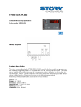
Controller interface
250 - 350 - 500
N


2
INDEX
1 CONSERVATION OF THE MANUAL ...................................................................................................................................... 5
1.1 GRAPHIC SYMBOLS USED IN THE MANUAL .............................................................................................................................. 5
2 PERMITTED USES ................................................................................................................................................................ 5
3 GENERAL SAFETY GUIDELINES ............................................................................................................................................ 5
3.1 PERSONAL PROTECTION EQUIPMENT ....................................................................................................................................... 5
3.2 HEALTH AND SAFETY OF WORKERS ........................................................................................................................................ 6
4 PURPOSES AND CONTENTS OF THE MANUAL ..................................................................................................................... 7
5 USER CONTROLLER INTERFACE ........................................................................................................................................... 7
5.1 MENU STRUCTURE DIAGRAM .................................................................................................................................................. 8
5.2 MENU CONTENTS .................................................................................................................................................................... 8
5.2.1 Setpoint menu [SEt] ....................................................................................................................................................... 8
(*) if the DHW function is active .................................................................................................................................................... 8
5.2.2 Password menu [PSS] .................................................................................................................................................... 9
5.2.3 Sensors menu [tP] .......................................................................................................................................................... 9
5.2.4 Alarms’ menu [Err] ........................................................................................................................................................ 9
5.2.5 Digital inputs menu [Id] ................................................................................................................................................. 9
5.2.6 Parameters menu [PAr] ................................................................................................................................................. 9
5.2.7 Operation’s hours menu [OHr]...................................................................................................................................... 9
5.2.8 Firmware Version [Fir] ................................................................................................................................................. 9
5.2.9 Alarm History [HiSt] .................................................................................................................................................... 10
5.2.10 USB menu [USb] .......................................................................................................................................................... 10
5.2.10.1 Firmware Upgrade [UPdF] ...................................................................................................................................................... 10
5.2.10.2 Parameters’ upgrade [UPPA] ................................................................................................................................................... 10
5.2.10.3 EXPORT PARAMETERS [ESP] ............................................................................................................................................ 10
5.2.11 Display ......................................................................................................................................................................... 11
5.2.12 LED .............................................................................................................................................................................. 11
5.3 INPUT/OUTPUT (I/O) PORTS OF THE SYSTEM ......................................................................................................................... 11
5.3.1 Standard configuration................................................................................................................................................. 11
5.3.2 Configuration with GI module accessory (code 00264034) ......................................................................................... 11
6 OPERATION CONTROL LOGIC ........................................................................................................................................... 12
6.1 DYNAMIC SETPOINT ADJUSTMENT ........................................................................................................................................ 12
6.1.1 Settings for standard climatic curves ........................................................................................................................... 13
6.2 SETPOINT ADJUSTMENT FROM 0-10V INPUT ......................................................................................................................... 13
6.3 CIRCULATOR ........................................................................................................................................................................ 14
6.3.1 Operation by mean of the thermoregulator .................................................................................................................. 14
6.3.2 Operation under thermoregulator call with periodic activation .................................................................................. 15
6.3.3 Operation with active electric heater ........................................................................................................................... 15
6.3.4 Continuous operation ................................................................................................................................................... 15
6.3.5 Linear adjustment of the circulating pump–double water ΔT ...................................................................................... 15
6.3.6 Air purging of the system.............................................................................................................................................. 15
6.4 COMPRESSORS’ CONTROL LOGIC .......................................................................................................................................... 16
6.4.1 Systems with multiple inverter compressors ................................................................................................................. 16
6.4.2 DHW logic control ....................................................................................................................................................... 16
6.4.3 Defrosting cycle ............................................................................................................................................................ 16
6.4.3.1 Forced manual defrost .................................................................................................................................................................. 16
6.4.4 Safe time periods .......................................................................................................................................................... 16
6.4.5 Modulation for oil return ............................................................................................................................................. 16
6.4.6 Inverter compressor control in cooling mode .............................................................................................................. 16
6.4.7 Heating function control .............................................................................................................................................. 17
6.5 HEAT DISSIPATION FAN MOTOR CONTROL ............................................................................................................................. 17
6.5.1 Fan speed control ......................................................................................................................................................... 18
6.5.2 Fan speed control in cooling mode .............................................................................................................................. 18
6.5.3 Fan speed control in heating mode .............................................................................................................................. 18
6.6 COMPRESSOR CRANKCASE HEATER ...................................................................................................................................... 19
6.7 ANTIFREEZE PROTECTION ELECTRIC HEATERS (IF THE KA ACCESSORY IS PRESENT CODE 00264035) .................................. 19
6.8 REMOTE FUNCTIONS ............................................................................................................................................................. 20
6.8.1 Remote switch On/Off ................................................................................................................................................... 20
6.8.2 Summer/Winter mode commutation ............................................................................................................................. 20

3
6.9
PLANT CIRCUIT REMOTE SENSOR .......................................................................................................................................... 20
6.10 ENABLEMENT OF DOMESTIC HOT WATER PRODUCTION (DHW) ............................................................................................ 21
6.10.1 Memorization of the sensor in heating mode ................................................................................................................ 21
6.10.2 Sanitary mode calling from digital input ...................................................................................................................... 22
6.10.3 Heating mode on domestic hot water tank ................................................................................................................... 22
7 OTHER CONTROL FUNCTIONS WITH THE PLANT MANAGEMENT GI-MODULE (OPTIONAL CODE 00264034) ..................... 22
7.1 AUXILIARY HEATING ELEMENTS ........................................................................................................................................... 22
7.1.1 Plant’s auxiliary electric heater ................................................................................................................................... 22
7.1.2 Auxiliary electric heater of the plant in defrost cycle ................................................................................................... 23
7.1.3 Auxiliary electric heater of DHW production .............................................................................................................. 23
7.1.4 One auxiliary electric heater for both plant side and DHW production ...................................................................... 23
7.1.5 Selection mode of auxiliary electric heaters ................................................................................................................. 23
7.1.6 Management of the circulator with active electric heater ............................................................................................ 23
7.2 BOILER ENABLEMENT ........................................................................................................................................................... 24
7.3 ACTIVATION OF AUXILIARY ELECTRIC HEATER AND BOILER DURING THE JOINT/IN SUBSTITUTION OPERATION TO THE
COMPRESSOR
..................................................................................................................................................................................... 24
7.3.1 Operation in heat pump mode ...................................................................................................................................... 25
7.3.2 In joint operation (ZONE I) .......................................................................................................................................... 25
7.3.3 In joint operation (ZONE II) ........................................................................................................................................ 25
7.3.4 In substitution operation .............................................................................................................................................. 25
7.3.5 Operation zone - activation of the auxiliary electric heater and boiler (plant circuit water temperature sensor is not
enabled) 25
7.3.6 Auxiliary systems offset management ........................................................................................................................... 29
7.4 DOUBLE SET-POINT ............................................................................................................................................................... 29
7.4.1 Settings ......................................................................................................................................................................... 30
7.5 MANAGEMENT OF THE SECONDARY CIRCULATOR (RELAUNCHING PUMP) ............................................................................ 32
7.6 SIGNALIZATIONS ................................................................................................................................................................... 32
7.6.1 Plant season signalization ............................................................................................................................................ 32
7.6.2 Defrosting cycle signalization ...................................................................................................................................... 32
7.6.3 Alarm signalization ...................................................................................................................................................... 32
7.6.4 Heat pump alarm codes ................................................................................................................................................ 33
8 AVAILABLE FUNCTIONS WITH TOUCH SCREEN_N (OPTIONAL CODE 00369719) ................................................................ 33
9 USER’S AND INSTALLER’S ALLOWED PARAMETERS .......................................................................................................... 33
9.1 SET POINT CONFIGURATION PARAMETERS ............................................................................................................................ 34
9.2 SETTINGS OF CONFIGURATION PARAMETERS ........................................................................................................................ 34
9.3 ALARMS CONFIGURATION PARAMETERS ............................................................................................................................... 35
9.4 ADJUSTMENT PARAMETERS .................................................................................................................................................. 36
9.5 CONDENSATION PARAMETERS .............................................................................................................................................. 36
9.6 PUMP CONFIGURATION PARAMETERS ................................................................................................................................... 37
9.7 DEFROSTING PARAMETERS ................................................................................................................................................... 37
9.8 COMPRESSOR PARAMETERS CONFIGURATION ....................................................................................................................... 37
9.9 “GI” MODULE CONFIGURATION PARAMETERS ..................................................................................................................... 37
9.10 CONFIGURATION PARAMETERS OF THE HEATING ELEMENTS ................................................................................................. 38
9.11 DEFROSTING PARAMETERS ................................................................................................................................................... 39
10 GLYCOL-WATER SOLUTIONS ............................................................................................................................................. 39
11 ALARMS ........................................................................................................................................................................... 39
11.1 E001 – HIGH PRESSURE ........................................................................................................................................................ 39
11.2 E002 – LOW PRESSURE ......................................................................................................................................................... 39
11.3 E016 – INVERTER PUMP THERMAL PROTECTION ................................................................................................................... 39
11.4 E003 - ON/OFF COMPRESSOR THERMAL PROTECTION ......................................................................................................... 40
11.5 E005 – ANTIFREEZE ALARM ................................................................................................................................................. 40
11.6 E006 – FLOW SWITCH ALARM ............................................................................................................................................... 40
11.7 E008 CONSTRAINED STOP OF THE COMPRESSORS FOR LACK OF LUBRICATION ...................................................................... 40
11.8 E018 – HIGH TEMPERATURE ................................................................................................................................................. 40
11.9 E042 – POOR HEAT EXCHANGE IN DEFROSTING CYCLE ......................................................................................................... 40
11.10 E101, E102 – I/O MODULE COMMUNICATION TIMEOUT ....................................................................................................... 40
11.11 ALARMS’ SENSORS ............................................................................................................................................................... 40
11.12 POWER FAILURE.................................................................................................................................................................... 40
11.13 [E020] INVERTED TRANSDUCERS ......................................................................................................................................... 41
11.14 INVERTER COMPRESSORS’ ALARMS ...................................................................................................................................... 41
11.15 ALARMS LIST ........................................................................................................................................................................ 42


5
1 CONSERVATION OF THE MANUAL
The manual has to be always kept for future reference. It has to be stored in a safe place, away from dusts and moisture. It has to
be also available and accessible to all users who shall consult it any time they are in doubt on how to operate the equipment.
The company reserves the right to modify its products and related manuals without necessarily updating previous versions of the
reference material. It declines also any responsibility for possible inaccuracies in the manual if due to printing or transcription
errors.
The customer shall store any updated copy of the manual or parts of it delivered by the manufacturer as an attachment to this
manual.
The company is available to give any detailed information about this manual and to give information regarding the use and the
maintenance of its own units.
1.1 Graphic symbols used in the manual
Indicates prohibited operations.
Indicates operations that can be dangerous for people and/or disrupts the correct operation of the equipment.
Hazardous electrical voltage - risk of electric shock
Indicates important information that the operator has to follow in order to guarantee the correct operation of the
equipment in complete safety. It indicates also general notes.
2 PERMITTED USES
• The company excludes any contractual and extra contractual liabilities for damages caused to persons, animals or objects, by
incorrect installation, setting and maintenance, improper use of the equipment, and the partial or superficial reading of the
information contained in this manual.
• These units have been designed only for heating and/or cooling water. Any other use not expressly authorized by the
manufacturer is considered improper and therefore not allowed.
• The execution of all works must be performed by skilled and qualified personnel and competent in the existing rules in the
country in which the appliance will be installed.
3 GENERAL SAFETY GUIDELINES
Before beginning any operation on the units, every user and operator has to be perfectly knowledgeable about the operation of
the equipment and its control functions and has to have read and understood the information listed in this manual.
3.1 Personal protection equipment
It’s necessary to use the below personal protective equipment when operating and maintaining the HP_OWER N units,
Protective clothing: Service man or who operates on the plant systems should wear protective clothing that
complies with the basic safety requirements currently in force. In case of slippery floors, users have to wear
safety shoes with non-slip soles.
Gloves: Protection gloves should be used during maintenance or cleaning operations.
Mask and goggles: Respiratory protection (mask) and eye protection (goggles) should be used during
cleaning and maintenance operations.

6
3.2 Health and safety of workers
The European Community has adopted a number of directives on workplace’s health and safety, which include 89/391/CEE,
89/686/CEE, 2009/104/CE, 86/188/CEE and 77/576/CEE directives. Every employer shall implement such provisions and ensure
that workers respect them:
It’s forbidden:
• To remove and/or tamper with any safety device.
• The access to the electrical board by unauthorized persons
• To carry out any work on the equipment under voltage
• To touch the equipment if you are not allowed.
• The use of the appliance by children or unassisted disabled persons.
• To touch the appliance when barefoot or parts of the body are wet or damp
• To clean the unit when the power is ‘ON’.
• To pull, remove or twist the electrical cables coming out from the unit.
• To step with your feet on the appliance, sit down and/or place any type of object.
• To spray or pour water directly on the unit.
• To dispose of, abandon or leave within reach of children packaging materials (cardboard, staples, plastic bags,
etc.) as they may represent an environmental and health hazards.
• To tamper with or replace parts of the equipment without the specific consent of the manufacturer. The
manufacturer shall have no whatsoever civilian or penal responsibility in case of unauthorized operations.
WARNING:
• Before proceeding, you should read the user’s-installer manual accompanying appliance.
• All the operations described below must be carried out only by QUALIFIED PERSONNEL.
• The wiring to the terminal block must be performed by qualified personnel.
• Any routine and/or not-routine maintenance operation shall be carried out when the equipment has been shut
down, disconnected from electric power supply.
• Do not put neither your hands nor inse
rt screwdrivers, spanners or other tools into moving parts of the
equipment
• The equipment’s supervisor and the service man have to receive suitable training for performing their tasks in
safety.
• The access to the electric panel is limited only for authorized personnel.
• Operators have to know how to use personal protective devices and have to know the accident-prevention
guidelines contained in national and international laws and norms.
• The operator’s workplace has to be kept clean, tidy and free from objects that may prevent free movements.
Appropriate lighting of the work place shall be provided so as to allow the operator to carry out the required
operations safely. Poor or too strong lighting can cause risks.
• Ensure that the work places are always adequa
tely ventilated and that aspirators are working, in good
condition and in compliance with the requirements of the laws in force.
• Not all the configurations can be simultaneously enabled and/or changed.
• Other values different than default ones can ensure the proper operation of the unit, in case of doubt about the
value to be set contact please our office.
• The company excludes any contractual and extra contractual liabilities for damages caused to persons, animals
or objects, by incorrect installation, setting and maintenance, improper use of the equipment, and the partial or
superficial reading of the information contained in this guide.
• The access to the electrical board by unauthorized persons is forbidden.
• It’s forbidden to carry out any work on the equipment under voltage.
•
It’s forbidden to touch the equipment if you are not allowed.
Requirements before performing electrical work on the control panel:
• Turn off the unit from the control panel ("OFF" displayed).
• Put the “QF” general differential switch on OFF position
• wait for 15 seconds before getting access to the electric board
• Check the ground connection before beginning any operation.
• Be sure that you are well insulated from the ground, with dry hands and feet, or by using insulating platforms
and gloves.
•
Check that there is no foreign material near the system.

7
4 PURPOSES AND CONTENTS OF THE MANUAL
This manual provides basic information for the configuration of the control panel of i-HP/i-HP LT units.
It is addressed to the installer/user of the unit: it is intended to operate this equipment efficiently, even if the user does not have
any previous specific knowledge of it.
Not all the described functions can be individually and/or at the same time selected. Please contact the technical office for any
information.
This manual describes the characteristics of the equipment when it was being put on the market; therefore, it may not capture
later technological improvements introduced by the company as part of its constant endeavour for enhancing the performance,
ergonomics, safety and functionality.
The company introduces also technological improvements and is not constrained to update the manuals for previous versions of
appliances that could not be compatible. So make sure to refer to the manual provided with the unit.
The user is recommended to follow the instructions contained in this manual, especially those concerning the safety and routine
maintenance.
5 USER CONTROLLER INTERFACE
It can be used to select the operating mode, and to reset the manual resetting alarms. The operating mode
changes as per the sequence below each time you press the Mode button:
off cool heat off
If the Domestic Hot Water (DHW) mode is enabled, the sequence is as follows:
off cool cool+san heat heat+sanoff
During the parameters’ setting, this button can be used to revert BACK to the previous level.
It allows you to enter into the setting menu parameters and to select the cool/summer, heat/winter and DHW
set point value.
UP button: In the setting mode, this button allows you to move up to a higher menu or to increase the value of a
parameter when you are in the “edit” mode.
DOWN button: In the setting mode, this button allows you to shift to a lower menu or to decrease the value of a
parameter when you are in the “edit” mode.
WARNING
All the operations described below must be carried out only by qualified personnel.
Not all the configurations can be simultaneously enabled and/or changed.
Other values different than those of default can ensure the proper operation of the unit, in case of doubt about
the value to be set contact please our office.
The company excludes any contractual and extra contractual liabilities for damages caused to persons, animals
or objects, by incorrect installation, setting and maintenance, improper use of the equipment, and the partial or
superficial reading of the information contained in this manual.

8
5.1 Menu structure diagram
Level 0 (U) = this level is always visible
Level 1 (M) = this level can be visible if you enter the maintainer or manufacturer password
Level 2 (C) = this level can be visible if you enter the manufacturer password
Level 3 (A) = this level can be visible only via Modbus.
5.2 Menu contents
The main functions of the menus are listed below, especially when there are some unambiguous functions. The main menu
manages the following parameters:
MENU
LABEL
LIVEL OF PASSWORD
OTHER CONDITIONS
Setpoint
SEt
User
Not accessible if the unit is connected to Touch Screen
Sensors
tP
Installer
---
Alarms
Err
User
Only in case of active alarms
Digital inputs
Id
Installer
---
Parameters
PAr
Installer
---
Password
PSS
User
---
Number of operating hours
oHr
Installer
---
USB
USb
Installer
Only if the USB flash drive is present with its files
Firmware Version
Fir
Installer
Version, Revision and Sub
Alarm History
HiSt
Installer
Only if you have data in the history
Enter in the password menu and insert its “password code” in order to enable an access with a greater privilege. Note that, once
you exit completely from the menus, the password concession will be lost and you should re-enter it in order to get access again.
5.2.1 Setpoint menu [SEt]
You can display and modify the different setpoints.
SETPOINT
DESCRIPTION
UNIT
DEFAULT
RANGE
Coo
First setpoint in the summer
°C
7.0
H03 ÷ Co2
HEA
First setpoint in the winter
°C
45.0
He2 ÷ H01
*SAn
DHW setpoint
°C
48.0
H02 ÷ H01
Coo2
Second setpoint in the summer
°C
18.0
Coo ÷ H03
HEA2
Second setpoint in the winter
°C
35.0
H02 ÷ Hea
**rCoo
---
°C
15.0
0.0 ÷ 80
**rHEA
---
°C
30.0
0.0 ÷ 80
**ACS
---
°C
0.0
0.0 ÷ 80
(*) if the DHW function is active
(**) Menu not active

9
5.2.2 Password menu [PSS]
Enter and confirm the password for the desired access level. The controller will automatically open the desired access level and
then the items which can be enabled from this level will appear.
5.2.3 Sensors menu [tP]
The value of the different sensors will appear. The number of visible sensor depends on the presence or not of the I/O expansion
modules.
Particular cases:
• Err = Sensor is faulty
• --- = Sensor not used (no function is associated to such sensor)
By entering the maintainer password in the menu of analog inputs "tP", at the level 1 of the structure diagram menu of the on-
board control panel, you can read the values of the current sensors:
tp DESCRIPTION Unit
t01
Water inlet temperature
(°C)
t02
Water outlet temperature
(°C)
t03
Compressor intake temperature
(°C)
t04
Compressor discharge temperature
(°C)
t05
Outdoor air temperature
(°C)
t06
Domestic hot water temperature (if enabled)
(°C)
t07
Plant water temperature remote sensor (if enabled)
(°C)
t09
Low pressure
(bar)
t10
High pressure
(bar)
5.2.4 Alarms’ menu [Err]
This menu appears only in case of alarms warning. You can check all active alarms. The alarms are divided by circuit for multi-
circuit units (the ALCx label allows to get access to the alarms of the circuit number x).
5.2.5 Digital inputs menu [Id]
You can check the status of the digital inputs as below:
0 = disabled input
1 = enabled input
----=input not configured
5.2.6 Parameters menu [PAr]
The parameters are collected into groups; each group is identified by a three-digit code, while the index of each parameter is
preceded by a letter.
DESCRIPTION
GROUP’S IDENTIFICATIVE CODE
PARAMETER’S INDEX
VISIBILITY
Configuration
CnF
H-
INSTALLER
Compressor
CP
C-
INSTALLER
Fan motor
FAn
F-
INSTALLER
Alarms
ALL
A-
INSTALLER
Regulation
rE
b-
INSTALLER
Pump
PUP
P-
INSTALLER
Electric heaters
Fro
r-
INSTALLER
Defrosting
dFr
d-
INSTALLER
Maximum Hz
LbH
L-
INSTALLER
Electronic valve
EEu
U-
INSTALLER
Offset
oFF
o-
INSTALLER
Inverter compressors
nCP
n-
INSTALLER
5.2.7 Operation’s hours menu [OHr]
You can display the number of operating hours of the compressors and of the pumps.
Press the ESC button for 3 seconds to resets the actual number of operating hours. Note that, you can enter into this menu only
via password.
5.2.8 Firmware Version [Fir]
Firmware version (uEr), Firmware revision (rEu) and sub (SUb) can be displayed.
Note that the menu can only be accessed with a password.

10
5.2.9 Alarm History [HiSt]
Appears only if there are active alarms.
5.2.10 USB menu [USb]
The available functions through the use USB flash drive that is connected to the board are indicated below.
5.2.10.1 Firmware Upgrade [UPdF]
You can update of the controller’s firmware in case of new versions release, this can be done by mean of a USB flash dive via its
proper port on the controller.
For the update:
1. Copy the updated files in the main directory of a USB pen-drive;
2. Place the unit in standby mode and turn it off, placing the main switch on OFF position;
3. Introduce the USB pen-drive into its port on the controller;
4. Turn ON the unit by placing the main switch in ON position;
5. Enter at the page of the parameters PRGPSSPRG(introduce the maintainer password)PRGUSBUPdFPRG.
The automatic firmware updating process starts with the selection of this option, the display shows the transferred data
in Kilobytes. When the update is completed the display shows "boot" then the LEDs will light up in sequence.
6. .Once the update is completed, the board returns to normal operation and the appliance is ready to start operation.
7. Turn off the unit by placing the main switch in OFF position.
8. Remove the USB pen-drive from its port.
9. Feed the unit by placing the main switch on the ON state.
5.2.10.2 Parameters’ upgrade [UPPA]
You can upgrade the parameters in case of new ones, using the USB pen-dive via its port on the controller.
For the updating:
1. Copy the update files in the main directory of a USB pen-drive;
2. Place the unit in standby mode and turn it off, placing the main switch in OFF position;
3. Introduce the USB pen-drive in its port on the controller;
4. Turn ON the unit by placing the main switch in the ON position;
5. Enter at the page of the parameters PRGPSSPRG(introduce the maintainer password)PRGUSBUPPAPRG.
The automatic firmware update process starts with the selection of this option, the display shows the transferred data in
Kilobytes. When the update is completed the display shows "boot" then the LEDs will light up in sequence.
6. Once the update is completed, turn off the unit by placing the main switch on OFF position.
7. Remove the USB pen-drive from its port.
8. Turn ON the unit by placing the main switch on the ON state
5.2.10.3 EXPORT PARAMETERS [ESP]
You can export the parameters from control board to USB pen, using the USB pen-drive via its port on the controller.
For exporting:
1 Place the unit in standby mode and turn it off, placing the main switch in OFF position;
2 Introduce the USB pen-drive in its port on the controller;
3 Turn ON the unit by placing the main switch in the ON position;
4 Enter at the page of the parameters PRGPSSPRG(introduce the maintainer password)PRGUSBESPPRG.
The automatic para
meters export process starts with the selection of this option, the display shows the transferred data in
Kilobytes. When the update is completed the display shows "boot" then the LEDs will light up in sequence.
5 Once the update is completed, turn off the unit by placing the main switch on OFF position.
6 Remove the USB pen-drive from its port.
7 Turn ON the unit by placing the main switch on the ON state
WARNING
All the operations with installer visibility must be carried out by qualified personnel.
The company excludes any contractual and extra contractual liabilities for damages caused to persons,
animals or objects, by incorrect installation, setting and maintenance, improper use of the equipment, and
the partial or superficial reading of the information contained in this manual.

11
5.2.11 Display
In normal view, it shows the outlet water temperature in tenths of degrees or the alarm code if at least one alarm is active. In case
of multiple alarms activation, it will display the first alarm, while the second appears when the first is reset. Into the menu mode,
the display depends on the current position where you are.
5.2.12 LED
Compressor LED
• ON if the compressor is running
• OFF if the compressor is off
• FLASHING if timings are in progress waiting for compressor’s start up
Sanitary water LED
• ON if sanitary mode is active
• OFF if the sanitary mode is not active
•
FLASHING if sanitary production in progress (sanitary valve is active)
Defrosting LED
• ON in defrost operating mode
• OFF if defrosting mode is disabled or completed
•
FLASHING if defrosting cycle interval’s time is in progress.
Antifreeze electric heater LED
• The LED is ON if the antifreeze electric heater is active.
Water pump LED
• The LED is ON if the water pump is running.
Alarm LED
• The LED is ON if an alarm is active.
Heating mode LED
• The LED is ON if the unit is the heating mode operation.
Cooling mode LED
• The LED is ON if the unit is the cooling mode operation.
5.3 Input/Output (I/O) ports of the system
The I/O (inputs/outputs) which can be configured in order to enable the control functions.
In order to configure the I/O ports from the onboard controller, you need to introduce the maintainer password in order to get
access to the parameters PRGPSSPRG(introduce the maintainer password)PRGParPRGCnF.
5.3.1 Standard configuration
(I/O) PORTS
Terminals
Function
Parameter
Description
Analog
input
ST6 / ST6
DHW temperature sensor
(It’s not active by default)
H17=6
Configurable analog input with NTC
sensor 10kΏ at 25°C β 3435
Configuration as a digital input is
possible (see §9)
Analog
input
ST7 / ST7
Plant water temperature remote sensor
(It’s not active by default)
H18=41
Configurable analog input with NTC
sensor 10kΏ at 25°C β 3435
Configuration as a digital input is
possible (see §9)
Digital
input
ID2 / ID2
Remote summer/winter operation mode
(It’s not active by default)
H46=3
Free voltage digital input
To enable this function, see. 6.8.2
(1)
Digital
input
ID3 / ID3 Remote on/off control from digital input H47=2
Free voltage digital input
Active function by default.
Digital
input
ST8 / ST8
Digital input for sanitary calling
(It’s not active by default)
H53=28 Free voltage digital input
(2)(
Output
DO4 (phase)
DO4N (neutral)
Undervoltage out for Antifreeze kit heating element
(It’s active by default if Antifreeze kit is present)
H82=14
Under voltage output single phase
230Vac, 50Hz, 2A (AC1)
Output
DO5 (phase)
DO5N (neutral)
Undervoltage output for DHW valve
(It’s not active by default)
H83=6
Under voltage output single phase
230Vac, 50Hz, 2A (AC1)
(3)
Output
DO6 (phase)
DO6N (neutral)
Undervoltage output of primary system circuit
external signal circulator
H84=7
Under voltage output single phase
230Vac, 50Hz, 2A (AC1)
(1)
Enabled in the factory
(2)
Output not available if Antifreeze kit is present
(3)
Output not available if primary system circuit external circulator is present
5.3.2 Configuration with GI module accessory (code 00264034)
When the GI optional plant management kit is present, furthermore to the ports of the standard configuration, you have also the
following I/O ports.

12
PORTS
TERMINALS
FUNCTION
PARAMETER
DESCRIPTION
DIGITAL
INPUT
ID2E / ID2E
Ambient thermostat
(Not enabled by default)
H56=19 Free voltage digital input
DIGITAL
INPUT
ID3E / ID3E
Double set point
(Not enabled by default)
H57=26 Free voltage digital input
OUTPUT
DO1E (phase)
DO1EN (neutral)
Plant auxiliary electric heater
(It’s not active by default)
H86=22
Under voltage output single phase
230Vac, 50Hz, 2A (AC1)
OUTPUT
DO2E (phase)
DO2EN (neutral)
Domestic hot water heating elements of
integration
(It’s not active by default)
H87=26
Under voltage output single phase
230Vac, 50Hz, 2A (AC1)
(1)
OUTPUT
DO3E (phase)
DO3EN (neutral)
Defrost cycle warning
(It’s not active by default)
H88= 21
Under voltage output single phase
230Vac, 50Hz, 2A (AC1)
Plant season warning
(It’s not active by default)
H88=31
Secondary circulator
(It’s not active by default)
H88=43
(1)
OUTPUT
DO4E (phase)
DO4EN (neutral)
Alarm warning
(It’s not active by default)
H89=24
Under voltage output single phase
230Vac, 50Hz, 2A (AC1)
Heat pump unit lockout warning
(It’s not active by default)
H89=47
OUTPUT
DO5E (phase)
DO5EN (neutral)
Double set point valve
(It’s not active by default)
H90=25
Under voltage output single phase
230Vac, 50Hz, 2A (AC1)
(1) It can be activated, only one warning (signalization) per output
6 OPERATION CONTROL LOGIC
The following operation logics are enabled by the master controller, mounted on the front panel of the unit.
6.1 Dynamic setpoint adjustment
The controller allows you to change the set-point by adding a value as a function of the outdoor air temperature sensor detection.
In this case, you need to change the values of the parameters from b08 to b14 according to the indications below (the settings are
the installer’s responsibility):
Parameters of the controller PAr->rE->
• b08 = dynamic setpoint, enabled = 1/ disabled = 0 (this parameter must be disabled in the case of the use of climatic
compensation by the optional remote touch screen panel Hi-T).
• b09 = offset max in cooling mode operation.
• b10 = offset max in heating mode operation.
• b11 = Outdoor temperature setting in cooling mode.
• b12 = Outdoor temperature setting in heating mode.
• b13 = Outdoor Temperature difference in cooling mode operation.
• b14 = Outdoor Temperature difference in heating mode operation.
Please see paragraph 9.4 for to change the parameters.
Curve of the setpoint variation as a function of the outside temperature:
COOLING
HEATING
Set temp. ext
b11
b09
Set temp. ext
b12
b10
Temp.
set
Offset <0
b13
Delta <0
Heat
Delta >0
Temp.
ext
Temp.
set
Offset >0
b14
Delta <0
Delta >0
Temp.
ext
Cool

13
6.1.1 Settings for standard climatic curves
HEATING
COOLING
CURVE
Setpoint Heat
Setpoint Cool
b08
B09
b10
B11
b12
B13
b14
A
33°C
--
1
--
-13°C
--
-5°C
--
25°C
B
38°C
--
1
--
-18°C
--
-7°C
--
27°C
C
45°C
--
1
--
-25°C
--
-9°C
--
29°C
D
50°C
--
1
--
-10°C
--
-8°C
--
28°C
E
55°C
--
1
--
-15°C
--
-5°C
--
25°C
F
--
5°C
1
5°C
--
37°C
--
-17°C
--
G
--
10°C
1
8°C
--
40°C
--
-20°C
--
6.2 Setpoint adjustment from 0-10V input
Another type of setting that allows to change the setpoint by adding (or subtracting) a value in function of the 0-10V analogue
input (if enabled). To enable the function, you must set the H22 parameter to be 40, and change the values of the parameter b15
(range 0-10), taking into account that if b20=0 input of 0-10V, if b20=1 ratiometric input type:
- b20=0 if the input is at 0 volts you will have the actual set point: set point (Coo/Hea) - b15/2.
- b20=0 if the input is at 5 volts the set point will be the set of (Coo/Hea) mode.
- b20=0 if the input is 10 volts you will have the actual set point: set point (Coo/Hea) + b15/2.
- b20=1 when the input is at 0%, the actual set point is: set point (Coo/Hea) - b15/2.
- b20=1 when the input is at 50%, the set point will be the set of (Coo/Hea) mode.
- b20=1 if the input is 100%, the actual set point is: set point (Coo/Hea) + b15/2.
The 0-10V signal must be applied to connector CN7 of the control board (see the wiring diagrams).
Note: In "cool" mode, considering that the setpoint by default is set to be 7°C, the parameter (b15) should not assume any value
greater than or equal to 6 in order to prevent that the new setpoint set from 0-10V input to take values below the threshold of the
antifreeze operation which is 4°C. Please see paragraph 9.4 for changing the parameters.

14
6.3 Circulator
The circulator of the pump can be set according to one of the following operation modes:
- Operation by thermo-regulator
- Operation by thermo-regulator with periodic activation
- Continuous operation (default)
The circulator SHUTDOWN immediately if:
− There is a lock pump alarm including the manual reset flow switch alarm.
− The unit is in stand-by mode or when it’s switched off from remote input (when it’s turned ON) It always turned off with a
delay equal to P02 (default two minute).
The circulator is always running if the antifreeze heaters are ON.
The circulator can be configured with the parameter P03 in order to operate independently than the compressor or under call.
0 = Continuous operation (in heating/cooling [default])
1 = Operation under the thermoregulatory call
Note: Whenever the flow switch alarm is automatically reset the pump is ON even if the compressor is off.
Contrarily, the circulator remains always in operation if the antifreeze heaters are on or when the hydraulic pump operates in
antifreeze mode. The operation in antifreeze mode will start if the water setting temperature decreases below P04 °C (default
value 5°C), and it will be disabled if the water setting temperature increases above P04+P05 °C (the default value of P05 is 2,0°C).
The adjustment of the circulator is linear (see Paragraph 6.3.5). Please see paragraph 9.6 for changing the parameters.
6.3.1 Operation by mean of the thermoregulator
During this operating mode (P03=1), the thermo-regulator actuates the circulator; after a time delay of P01 seconds from startup
of the circulator pump, the compressor also will turn on. However, during the power off status, the circulator pump turns off with
a delay time of P02 minutes after turning off status with thermo-regulator actuation (the turning off status is corresponding to the
off status of the compressor).
If the flow switch alarm is active in automatic reset, the pump is anyway on even if the compressor is off.
If you enable the operation of the unit from "DI3" digital input corresponding to the remote "on-off" the circulator will be
activated immediately for 2 minutes regardless of the internal thermoregulation of the unit (the activation of water recirculation in
the plant leads to the correct activation of the thermoregulation).

15
6.3.2 Operation under thermoregulator call with periodic activation
The function is disabled if P17= 0 (default). If the pump is set to operate by thermos-regulator actuation (P03 = 1), it will be
activated periodically for a time period defined by the parameter P17 (in seconds) after a counting time set by the parameter P16
(in minutes), activated when the pump is turned off for satisfied thermoregulation.
In the case of the activation of the flow switch alarms with automatic reset the pump is still ON even if the compressor is off.
The periodic function is interrupted also in the case of the intervention of the antifreeze thermo-regulator which constrains the
operation of the pump. Please see paragraph 9.6 for changing the parameters.
6.3.3 Operation with active electric heater
The presence of the optional module “GI” is required for this function, when the I/O resources of the standard configuration are
not sufficient.
See paragraph 7.1.6
6.3.4 Continuous operation
This operating mode is enabled if P03=0, the pump is always turned on and it turns off only when the unit is not operating (OFF)
after P02 minutes.
6.3.5 Linear adjustment of the circulating pump–double water ΔT
The analog output varies according to difference in temperature between water inlet and water outlet of the heat exchanger. The
controller is enabled setting P12 = 1 and is defined by the following parameters:
• P06 set difference in temperature between water inlet of modulating pump in heating mode
• P07: maximum speed of the modulating pump
• P08: minimum speed of the modulating pump
• P09: set ΔT inlet/outlet water of heat pump in cooling mode(°C)
• P10: Delta modulating pump (°C)
− In cooling mode: ΔT= [Water inlet temperature] – [Water outlet temperature]
− In heating mode: ΔT = [Water outlet temperature] – [Water inlet temperature]
Example in cooling:
If the difference in temperature between water inlet and outlet is greater than P09 + P10, the pump will run at maximum speed.
If the difference temperature between water inlet and outlet is less than P09 - 0.2°C, the pump will run the minimum speed.
In the other cases, the pump modulates trying to match the temperature difference with P09. For the heating mode, the same
considerations are valid with replace only P06 with P09. Please see paragraph 9.6 for changing the parameters.
Warning: During the DHW production mode, the pump is constrained to run at its maximum speed.
In domestic hot water production mode, the pump will operate at the maximum speed.
6.3.6 Air purging of the system
This function allows the air purging of the system, during this operation, the circulator runs at its maximum speed.
To enable the function:
1. Put the controller in OFF mode
2. Enter at the parameters PRGPSS PRG(introduce the maintainer password)
3. Press simultaneously for 3 seconds the buttons UP and DOWN.
The circulator of the plant will run at the maximum speed for 5 minutes then it stops the operation.
It is possible to stop manually the air purge cycle function of the system by pressing the MODE/ESC button, or by pressing
simultaneously the UP and DOWN buttons for 3 seconds.

16
During this function, the flow-switch alarm is deactivated.
6.4 Compressors’ control logic
When the compressors are all switched off, in conjunction with the pre-opening of the expansion valve, the inversion valve
reverses the flow direction for 5 seconds to the opposite one that is required by the ongoing operating mode in order to allow the
rebalancing with optimal pressures for starting operation with the first step.
6.4.1 Systems with multiple inverter compressors
For the systems with multiple inverter compressors, if the required output capacity by the thermoregulator is greater than 80% for
a continuous duration of 60 seconds, the compressor’s activation becomes necessary where there is availability of other
compressor.
The already activated compressor goes into the lowest frequency until the last activated compressor goes into the lowest
frequency too.
After that, both compressors are brought to the frequency of 45Hz (lubrication and equalization frequency) for 180 seconds. At
the end of this phase, the compressors follow what is required by the thermoregulator.
If the required output capacity is the minimum one by the thermoregulator to all operating inveter compressors for more than
180 seconds, then one of compressors is called to stop operation.
Once the release has taken place, wait 60 seconds again before releasing the next step.
If one of the inverter compressors is in alarm for which the activation of the respective compressor is no longer possible, the alarm
code will be displayed and the setting will continue with the indicated modes while keeping off the inverter compressor in alarm.
To define the behaviour of the remaining inverter compressors:
If N06 = 0 all the inverter compressors stop operation.
If N06 = 1 only the inverter compressor which is in alarm stops operation, the remaining ones continue operate normally.
6.4.2 DHW logic control
The maximum serviceable capacity is used always in case of DHW mode operation (like if the controller regulates the compressors
to run always at 100% capacity).
They are active however the various limitations of the maximum frequency that are related to the envelope and to the limitation
for maximum power consumption.
6.4.3 Defrosting cycle
The defrost cycle function is available only in heat pump mode and is used to prevent the frost formation on the surface of the
air/air coil. The frost formation on the evaporator, which occurs more frequently at very low ambient temperatures, further the
important decreasing of the thermal efficiency of the unit, it can lead also to the risk of damaging the unit itself.
In defrosting cycle, after 60 seconds duration of operation at lower frequency 30Hz, the compressor goes into a regime with fixed
frequency of 30 Hz. In this case, the compressor speed remains constant and cannot be adjusted.
Note: In case of remote switch Off during the defrost cycle, the unit will terminate this process before stopping operation.
6.4.3.1 Forced manual defrost
If the appliance is in heating mode, you can constrain it manually to operate in the defrosting process by pressing at the same time
the UP, DOWN, and ENTER buttons for 3 seconds.
6.4.4 Safe time periods
The compressors respect the minimum waiting time for the turning on and off actions (regardless of the configuration and if they
are inverters or ON/OFF type):
C01 = Minimum Off time of a compressor # 300 sec (default).
C02 = Minimum time between two start-up of the same compressor # 360 sec (default).
C03 = M
inimum delay time between the start-up of a certain compressor and the next one # 10 sec (default).
C04 = Minimum delay time between the shutdown of a compressor and the next one # 0 sec (default).
6.4.5 Modulation for oil return
If this function is enabled in the factory, the return oil cycle will be performed during the compressor startup at the frequency of
45Hz for 90 seconds duration.
6.4.6 Inverter compressor control in cooling mode
The management of the compressors depends on the ambient temperature and on the water temperature setpoint.
The regulation is proportional + integral (PI) with:
ST = regulation temperature sensor
Set cool (G01) = setting of cooling setpoint
b01 = cooling regulator proportional band
b05 = compressor control delta cut-off
b25 = compressor control delta cut-on

17
b07 = integral time
HzMin = Minimum frequency of operation derived from the algorithms of limitation
HzMaxReg = Maximum working frequency of the compressor in cooling mode based on the limitations described in the
previous paragraphs
HP_OWER 250N
HP_OWER 350N
HP_OWER 500N
b05 (°C)
0,2
0,2
0,2
b25 (°C)
3,5
3,5
3,5
The following curve shows the adjustment without integral component (b07 = 0)
During the start-up, the compressor initiates at the minimum speed C12 or C14 (as defined from the envelope) for a given time
period equal to C11 and then changes its speed to C13 for a period equal to C51-C11.
6.4.7 Heating function control
The compressors are active in heating mode if the heat pump is enabled
• H09 = Configuration of the heat pump presence parameter (0 = Heat pump not present; 1 = heat pump is present)
• ST = regulation temperature sensor
• Set heat G02= setting of heating setpoint
• b02 = compressor regulation band in heat pump mode
• b05 = compressor control delta cut-off
• b25 = compressor control delta cut-on
• b07 = integral time
• HzMin = Minimum frequency of operation derived from the algorithms of limitation
• HzMaxReg = Maximum working frequency of the compressor in cooling mode based on the limitations described in the
previous paragraphs
For the values of b05 and b25, make reference to the table in the previous chapter.
The curve shows the adjustment without integral component (b07 = 0)
During the start-up, the compressor initiates at the minimum speed C12 or C14 (as defined from the envelope) for a given time
period equal to C11 and then changes its speed to C13 for a period equal to C51-C11.
6.5 Heat dissipation fan motor control
The control of the dissipation is as a function of the condensing pressure in chiller mode operation, whereas, it depends on the
evaporation pressure in heat pump mode operation.
The adjustment of the fan speed occurs depending on the operation of the compressor.
The fan stop is bypassed for a duration equal F12 beginning from a compressor startup of the circuit. During this period, if the
controller requires the cut-off, the fan will run at minimum speed. Please see paragraph 9.5 for changing the parameters.

18
6.5.1 Fan speed control
The fan speed control is a function of the condensing pressure in chiller mode and the evaporation pressure in heat pump mode.
The fan speed can be independently controlled from the compressors or under the actuation of the same.
F05= fan output mode
- 0: if all the compressors of the circuit are switched off and the fan is switched off. The fan stop is bypassed for a period
equal to F12 beginning from a compressor startup of the circuit. During this period, if the controller requires the cut-off,
the fan will run at minimum speed.
- 1: The fan control is independent from the compressor (the fan motor operates only according to the condensing
pressure). Please see paragraph 9.5 for changing the parameters.
6.5.2 Fan speed control in cooling mode
The fan speed control in cooling mode occurs according to the diagram shown below, where:
F06 = Minimum fan speed in cooling mode;
F07 = Maximum silent fan speed in cooling mode
F08 = Set temperature/pressure to the minimum fan speed in cooling mode
F09 = Fan motor linear band in cooling mode
F10 = Delta cut-off of the fan
F11 = Cut-off hysteresis and silent/maximum fan speed
F13 = Maximum fan speed in cooling mode
F14 = Set temperature/pressure to the maximum fan speed in cooling mode
F6-F10 = Set forced fan stop for low condensing pressure
6.5.3 Fan speed control in heating mode
The fan speed control in heating mode follows the diagram shown below, where:
F10 = Delta cut-off of the fan in cooling/heating mode
F11 = Cut-off hysteresis in cooling/heating mode
F15 = Minimum fan speed in heating mode
F16 = Maximum silent fan speed in heating mode
F17 = Set pressure for the minimum fan speed in heating mode
F18 = Fan speed linear band in heating mode
F19 = maximum fan speed in heating mode
F20 = Set pressure for the maximum fan speed in heating mode
F17+F10 = Set forced fan stop for high evaporating pressure
The fan speed can be controlled via analog/digital outputs or, alternatively, via serial on the same serial of the modulating
compressor. Please see paragraph 9.5 for changing the parameters.

19
6.6 Compressor crankcase heater
The crankcase heater operates when the compressor remains off for at least 30 minutes and if the discharge temperature is below
20°C (with hysteresis of 2.0°C). When the compressor restarts, the crankcase heater will stop.
6.7 Antifreeze protection electric heaters (if the KA accessory is present code 00264035)
The electric heaters of water antifreeze, installed on the outer surfaces of the evaporator plates, activates even when the unit is
switched off (but energized) if the outlet water temperature goes below r02 °C (default is 4°C) in heating mode or below r03 °C
(default is 4°C) in cooling mode and in shut off condition. The same electric heaters are switched off when the temperature
measured by the outlet water sensor exceeds r02+r06 in heating mode or r03+r06 in cooling mode and in shut off condition (the
default value is r06=2,0°C). The heating cable placed on the basement of the appliance turns on when the outdoor air temperature
decreases below 3°C and the unit starts the defrosting cycle (or if r19=0 even if the unit is not in defrosting cycle, or in stand-by
mode). It will be deactivated if the outdoor temperature exceeds 5°C or the last defrosting cycle is concluded after more than r19
minutes (default 10 minutes) (with r19≠0).
In case you want to produce gelid water, it is necessary to modify the actions of antifreeze resistances, as well as the set of
activation of the antifreeze alarm (A08 = 4°C by default) and its hysteresis (A09 = 3.0°C by default).
/