Page is loading ...

EVCO S.p.A. Vcolor 679/689 | Installer manual ver. 2.1 | Code 144VC679E214
page
1
of
78
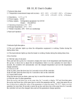
Vcolor 679/689
Controllers for retarding-proofing or proofing
cabinets and rooms with customised graphic skin
ENGLISH
INSTALLER MANUAL ver. 2.1
CODE 144VC679E214

EVCO S.p.A. Vcolor 679/689 | Installer manual ver. 2.1 | Code 144VC679E214
page
2
of
78
Important
Read this document carefully before installation and before using the device and take all the prescribed precautions. Keep this
document with the device for future consultation.
Only use the device in the ways described in this document. Do not use the device as a safety device.
Disposal
The device must be disposed of according to local regulations governing the collection of electrical and electronic equipment.

EVCO S.p.A. Vcolor 679/689 | Installer manual ver. 2.1 | Code 144VC679E214
page
3
of
78
Contents
1 INTRODUCTION .................................................... 4
1.1 Introduction ......................................................... 4
1.2 Models available and main features ......................... 5
2 MEASUREMENTS AND INSTALLATION ...................... 8
2.1 Format features .................................................... 8
2.2 Control module measurements and installation ......... 8
2.3 User interface measurements ................................. 8
2.4 User interface installation ...................................... 9
2.5 EVC20P52N9XXX10 – EVC20P52N9XXX12 expansion
module measurements and installation .................. 10
2.6 Installation precautions ....................................... 10
3 ELECTRICAL CONNECTION ................................... 11
3.1 Vcolor 679/689 M electrical connection .................. 11
3.2 Vcolor 679/689 L electrical connection................... 12
3.3 Precautions for electrical connection ...................... 13
4 RETARDING-PROOFING OR PROOFING OPERATION 14
4.1 Initial information ............................................... 14
5 FIRST-TIME USE ................................................. 14
5.1 Operating modes ................................................ 14
5.2 Operating the device ........................................... 14
6 NAVIGATION ...................................................... 16
6.1 Initial information ............................................... 16
6.2 Home screen ...................................................... 16
6.3 Cycle running screen ........................................... 17
6.4 Screen saver ...................................................... 20
6.5 Settings screen .................................................. 20
6.6 Welcome page .................................................... 24
7 OVERVIEW OF THE FUNCTIONS ............................ 25
7.1 Automatic cycle .................................................. 25
7.2 Manual cycles ..................................................... 29
8 MAIN FUNCTIONS ............................................... 30
8.1 Automatic cycle .................................................. 30
8.2 Heating cycle ..................................................... 34
8.3 Cooling cycle (for retarding-proofing only) ............. 35
8.4 Pre- cooling cycle (for retarding-proofing only) ....... 36
8.5 Recipe book ....................................................... 37
9 REGULATIONS .................................................... 38
9.1 Pre-cooling (for retarding-proofing only) ................ 38
9.2 Temperature regulation ....................................... 38
9.3 Humidity regulation ............................................ 39
10 LOAD MANAGEMENT ........................................... 41
10.1 ON-OFF / variable speed compressor management
(for retarding-proofing only) ................................ 41
10.2 Pump-down management (for retarding-proofing
only) ................................................................. 41
10.3 Evaporator fan management ................................ 41
10.4 Defrost management (for retarding-proofing only) .. 42
10.5 Heater management ............................................ 42
10.6 Humidity production output management (only if E3
= 0) .................................................................. 43
10.7 Humidity injection output management (only if E3 =
0) ..................................................................... 43
10.8 Mistral humidifier management via the serial port
(only if E3 = 1) ................................................... 43
10.9 Dehumidification management.............................. 44
10.10 Condenser fan management (for retarding-proofing
only) ................................................................. 44
10.11 Cabinet light management ................................... 44
10.12 Door frame management (for retarding-proofing
only) ................................................................. 44
10.13 On/stand-by relay configuration ............................ 44
10.14 Water load management ...................................... 44
10.15 Dripping heater management ............................... 45
10.16 Output testing .................................................... 45
10.17 Testing cycle ...................................................... 45
11 CONNECTIVITY ................................................... 46
11.1 Initial information ............................................... 46
11.2 EPoCA cloud platform .......................................... 47
12 USB PORT MANAGEMENT ..................................... 48
12.1 Available functions .............................................. 48
13 ALARMS ............................................................. 49
13.1 Active alarms ..................................................... 49
13.2 Humidifier alarms................................................ 49
13.3 List of alarms ..................................................... 50
14 PARAMETERS...................................................... 56
15 ACCESSORIES .................................................... 69
15.1 4 relay expansion ................................................ 69
15.2 Phase cutting speed regulator ............................... 69
15.3 EVCO Inverter .................................................... 69
15.4 Mistral humidifier ................................................ 70
15.5 Safety transformer .............................................. 70
15.6 Non-optoisolated RS-485/USB serial interface ........ 70
15.7 USB plug for panel installation .............................. 70
15.8 Connecting cables ............................................... 71
15.9 4GB USB flash drive ............................................ 71
15.10 EVlinking Wi-Fi RS-485 module ............................. 71
15.11 IoT EV3 Web gateway.......................................... 71
15.12 NTC temperature and humidity probe .................... 71
15.13 Humidity transducer 4÷20 mA .............................. 72
16 TECHNICAL SPECIFICATIONS ............................... 73
16.1 Technical data .................................................... 73

EVCO S.p.A. Vcolor 679/689 | Installer manual ver. 2.1 | Code 144VC679E214
page
4
of
78
1 INTRODUCTION
1.1 Introduction
Vcolor 679/689 is a controller for retarding-proofing or proofing cabinets and rooms which delivers high performance and precision
regulation, thanks to a modulating output which gives control of up to ten evaporator fan speeds. The evaporator fan can also be
modulated using an EVCO inverter. In the 689 models, the modulating output can also be set to control variable speed compressors.
The controller's firmware can control an ultrasonic humidifier from the Mistral series via the RS-485 serial port.
By simply setting a parameter, the controller can be configured to manage retarding-proofing and proofing automatic cycles. Variables
such as temperature, humidity, fan intensity and duration can be managed independently for each phase. As well as three-phase
proofing cycles (re-awakening, proofing and baking delay), with blocking and holding added in the retarding-proofing cycles, there are
also manual cycles such as heating for proofing and cooling/pre-cooling/heating for retarding-proofing.
The controller’s innovative programmable platform gives manufacturers the freedom to personalise the graphic skin and programmes
and add new languages. All they have to do is compile an ODS file and upload it using a flash drive to the USB port on the user
interface. Users can store up to 100 programmes, match them to a set of preloaded images and move them to the favourites.
Users can interact remotely with their equipment and start up/stop working cycles using the EPoCA® cloud platform with Wi-Fi or
Ethernet connectivity (which also enables alternative or parallel control through MODBUS TCP). For more details, compare all the
connectivity options in the Technical Data table and consult the Management and Monitoring Products/Systems and the Connectivity
Products/Devices sections of our website.
The controller has an open frame board and a remote user interface which consists of a 5-inch (M) or 7-inch (L) capacitive TFT touch-
screen graphic display in glass which is installed horizontally either semi-recessed into the front or flush with the panel.

EVCO S.p.A. Vcolor 679/689 | Installer manual ver. 2.1 | Code 144VC679E214
page
5
of
78
1.2 Models available and main features
The table below shows the main features of the models available.
MAIN FEATURES
KITS OPTIONS
Vcolor 679 M &
L
with PWM
output
Vcolor 689 M &
L
with 0-10 V
output
I/O
expansion
module
Speed
regulator Inverter Humidifier
EVC20P52N9
XXX12*
EVDFAN1
(solo per
modelli
679)
Compact,
Slim e Slim
Power
Mistral
Power supply
Control module 115...230 VAC 115...230 VAC
User interface Powered by the
control module
Powered by an
external
transformer
12VAC/20VA
Optional modules 115...230 VAC 230 VAC 230 VAC 115...230 VAC
Analogue inputs
Cabinet probe (PTC/NTC) • •
Evaporator probe (PTC/NTC) • •
Condenser probe (PTC/NTC) • •
Humidity transducer (4-20 mA) • •
Temperature (NTC)/humidity
EVHTP520 probe • •
Digital inputs (for NO/NC
contact)
Door switch • •
Configurable multi-purpose 1
(default high pressure alarm) • •
Configurable multi-purpose 2
(default pump-down completed) • •
Configurable multi-purpose 3
(default low pressure alarm) • •
Modulating output
Can be configured as 0-10 V to
module the evaporator fan or as
frequency for variable speed
compressors
•
Can be configured as PWM for
EVDFAN1 speed regulator
(evaporator fan)
•

EVCO S.p.A. Vcolor 679/689 | Installer manual ver. 2.1 | Code 144VC679E214
page
6
of
78
MAIN FEATURES
KITS OPTIONS
Vcolor 679 M &
L
with PWM
output
Vcolor 689 M &
L
with 0-10 V
output
I/O
expansion
module
Speed
regulator Inverter Humidifier
EVC20P52N9
XXX12*
EVDFAN1
(solo per
modelli
679)
Compact,
Slim e Slim
Power
Mistral
Digital outputs (sealed relays
A res. @ 250 VAC)
Configurable K1 (default
compressor) 16 A 16 A
Configurable K2 (default cabinet
light) 8 A 8 A
Configurable K3 (default humidity
injection) 8 A 8 A
Configurable K4 (default
dehumidifier) 8 A 8 A
Configurable K5 (default defrost) 8 A 8 A
Configurable K6 (default heater) 16 A 16 A
Configurable K7 (default humidity
production) 16 A 16 A
Configurable K8 (default pump-
down) 8 A 8 A
Configurable K9 (default door
heater) 8 A 8 A
Configurable K10 (default
sanitation) 30 A
Configurable K11 (default
on/stand-by) 16 A
Configurable K12 (alarm) 8 A
Configurable K13 (default
condenser fan) 16 A
Communications ports
RS-485 MODBUS • •
USB • •
Connectivity
RS-485 MODBUS RTU (built-in) • •
Wi-Fi EPoCA/MODBUS TCP
(optional through the EVlinking
Wi-Fi module powered by
controller)
• •
Ethernet EPoCA/MODBUS TCP
(optional through EV3 Web gateway)
• •

EVCO S.p.A. Vcolor 679/689 | Installer manual ver. 2.1 | Code 144VC679E214
page
7
of
78
MAIN FEATURES
KITS OPTIONS
Vcolor 679 M &
L
with PWM
output
Vcolor 689 M &
L
with 0-10 V
output
I/O
expansion
module
Speed
regulator Inverter Humidifier
EVC20P52N9
XXX12*
EVDFAN1
(solo per
modelli
679)
Compact,
Slim e Slim
Power
Mistral
Other features
Clock • •
Alarm buzzer • •
Management of automatic and
manual cycles • •
Fan intensity management • • •
Integrated humidifier
management •
Saving HACCP files • •
"Programmes" function • •
* The code refers to the I/O expansion module with HC sealed relays
For more information see section 16 “TECHNICAL SPECIFICATIONS”.
The table below lists the purchasing codes of the available models:
Purchasing codes
Models with PWM output
Vcolor 679 M (control module + 5” user interface):
EVCMC679N9EH (flush fit installation)
EVCMC679N9EFH (semi-recessed installation)
Vcolor 679 L (control module + 7” user interface):
EVCLC679N9EH (flush fit installation)
EVCLC679N9EFH (semi-recessed installation)
Models with 0-10 V output
Vcolor 689 M (control module + 5” user interface):
EVCMC679N9EH (flush fit installation)
EVCMC689N9EFH (semi-recessed installation)
Vcolor 689 L (control module + 7” user interface):
EVCLC689N9EH (flush fit installation)
EVCLC689N9EFH (semi-recessed installation)
For more models, contact the EVCO sales network.

EVCO S.p.A. Vcolor 679/689 | Installer manual ver. 2.1 | Code 144VC679E214
page
8
of
78
2 MEASUREMENTS AND INSTALLATION
2.1 Format features
The control module is available in a split version with an open frame board. User interfaces are available in 5- or 7-inch versions for
horizontal operation and have capacitive colour TFT touch-screen graphic displays.
2.2 Control module measurements and installation
Installation of the control module is on a flat surface with spacers.
2.3 User interface measurements
The user interface is available in the model which is installed flush and the model which is semi-recessed into the front. The
measurements vary according to the model, as illustrated below in mm (in).
Vcolor 679/689 M interface

EVCO S.p.A. Vcolor 679/689 | Installer manual ver. 2.1 | Code 144VC679E214
page
9
of
78
Vcolor 679/689 L interface
2.4 User interface installation
Depending on the model, installation can be:
- flush, from behind the panel with threaded studs (not provided) welded to hold it in place;
- semi-recessed, from the front of the panel with spring clips to hold it in place.

EVCO S.p.A. Vcolor 679/689 | Installer manual ver. 2.1 | Code 144VC679E214
page
10
of
78
2.5 EVC20P52N9XXX10 – EVC20P52N9XXX12 expansion module measurements and
installation
The diagram below shows the measurements of the 4 relay expansion. Installation is on a flat surface with spacers.
2.6 Installation precautions
- Ensure that the working conditions for the device (operating temperature, humidity, etc.) are within the set limits. See
section 16 “TECHNICAL SPECIFICATIONS”.
- Do not install the device close to heat sources (heaters, hot air ducts, etc.), equipment with a strong magnetic field (large
diffusers, etc.), in places subject to direct sunlight, rain, damp, excessive dust, mechanical vibrations or shocks.
- Any metal parts close to the control module must be far enough away so as not to compromise the safety distance.
- In compliance with safety regulations, the device must be installed properly to ensure adequate protection from contact
with electrical parts. All protective parts must be fixed in such a way as to need the aid of a tool to remove them.

EVCO S.p.A. Vcolor 679/689 | Installer manual ver. 2.1 | Code 144VC679E214
page
11
of
78
3 ELECTRICAL CONNECTION
3.1 Vcolor 679/689 M electrical connection
The diagram below shows the Vcolor 679/689 M electrical connection.
*The USB communications port makes it possible to upload and download the device settings and personalise the graphics, recipes and
languages using an ordinary USB flash drive (see section 11 “USB PORT MANAGEMENT”).
**The RS-485 MODBUS communications port enables connection to the Parameters Manager set-up software or to the modules for Wi-
Fi (EVlinking Wi-Fi) or Ethernet (EV3 Web) connectivity to manage the unit using the EPoCA cloud platform or MODBUS TCP systems
(see section 10 “CONNECTIVITY”).

EVCO S.p.A. Vcolor 679/689 | Installer manual ver. 2.1 | Code 144VC679E214
page
12
of
78
3.2 Vcolor 679/689 L electrical connection
The diagram below shows the Vcolor 679/689 L electrical connection.
*The USB communications port makes it possible to upload and download the device settings and personalise the graphics, recipes and
languages using an ordinary USB flash drive (see section 11 “USB PORT MANAGEMENT”).
**The RS-485 MODBUS communications port enables connection to the Parameters Manager set-up software or to the modules for Wi-
Fi (EVlinking Wi-Fi) or Ethernet (EV3 Web) connectivity to manage the unit using the EPoCA cloud platform or MODBUS TCP systems
(see section 10 “CONNECTIVITY”).

EVCO S.p.A. Vcolor 679/689 | Installer manual ver. 2.1 | Code 144VC679E214
page
13
of
78
3.3 Precautions for electrical connection
- Do not use electric or pneumatic screwdrivers on the terminal blocks of the device.
- If the device is moved from a cold to a warm place, the humidity may cause condensation to form inside. Wait about an
hour before switching on the power.
- Make sure that the supply voltage, electrical frequency and power of the device correspond to the local power supply. See
section 1516 “TECHNICAL SPECIFICATIONS”.
- Disconnect the device from the power supply before doing any type of maintenance.
- Locate the power cables as far away as possible from those for the signal.
- To reduce reflections on the signal transmitted along the cables connecting the user interface to the control module, it is
necessary to fit a termination resistor.
- For repairs and for further information on the device, contact the EVCO sales network.

EVCO S.p.A. Vcolor 679/689 | Installer manual ver. 2.1 | Code 144VC679E214
page
14
of
78
4 RETARDING-PROOFING OR PROOFING OPERATION
4.1 Initial information
Vcolor 679/689 is a controller which, by simply setting a parameter, can be configured to manage retarding-proofing cabinets and
rooms (E12 = 1) or proofing cabinets and rooms (E12 = 0). All the cooling regulations are for retarding-proofing only; care must
therefore be taken when configuring the controller for proofing (E12 = 0), that no parameters are set for cooling (see section 14.
PARAMETERS).
Automatic management of the complete dough cycle consists of three phases in the proofing configuration (re-awakening, proofing and
baking delay), plus two more for retarding-proofing (blocking and holding). There are also manual cycles such as heating for proofing
and cooling/pre-cooling/heating for retarding-proofing.
This manual gives instructions how to use the controller, only pointing out when there are differences between the two configurations.
5 FIRST-TIME USE
5.1 Operating modes
The controller has the following operating modes:
- “OFF” (no power to the device);
- “STAND-BY” (the device is powered but switched off);
- “ON/HOME” (the device is powered, switched on and awaiting start-up of an operating cycle);
- “RUN” (the device is powered, switched on and running an operating cycle).
Terminology: “device switch-on” means going from “stand-by” to “ON” and “device switch-off” from “ON” to “stand-by”.
If there is a power failure, when power is restored the device will return to the mode set before the failure.
5.2 Operating the device
Follow these instructions to operate the device:
1. Install the device as shown in section 2 “MEASUREMENTS AND INSTALLATION”, taking all the precautions mentioned in
paragraph 2.6 “Installation precautions”.
2. Make the electrical connection as shown in section 3 “ELECTRICAL CONNECTION”, taking all the precautions mentioned in
paragraph 3.3 “Precautions for electrical connection”.
3. Connect the power supply to the device: the device will show a splash screen for 10 seconds.
Once loading is complete, the device will display the mode it was in before being powered down:
- stand-by screen, press the central area to move to the Home screen;
- the Home screen.
Splash screen
Stand-by screen

EVCO S.p.A. Vcolor 679/689 | Installer manual ver. 2.1 | Code 144VC679E214
page
15
of
78
Retarding-proofing
Home screen (E12=1)
Proofing Home screen (E12=0)
To switch the device on, press the central key on the stand-by screen; to switch the device off, press the key on
the lower part of the Home screen.
N.B.:
If the power supply has been cut off long enough to cause a clock error (RTC alarm), it will be necessary to reset the date
and time.
4. From the settings key on the stand-by screen, enter the GENERAL SETTINGS – DATE/TIME menu to set the current
date and time; it is also possible to set either the EUROPEAN or US format in this screen.
EUROPEAN FORMAT
US FORMAT
5. From the settings key on the stand-by screen, enter the GENERAL SETTINGS – LANGUAGE menu to set the language;
the available languages are given below.
6. From the settings key on the stand-by screen, enter the SERVICE – PARAMETER SETTINGS menu and configure the
device. The complete list of parameters is given in section 14 “PARAMETERS”.

EVCO S.p.A. Vcolor 679/689 | Installer manual ver. 2.1 | Code 144VC679E214
page
16
of
78
6 NAVIGATION
6.1 Initial information
Navigating the menus is intuitive, based on touch technology.
- To enter into a procedure, touch the menu or the corresponding icon.
- To exit a procedure and, in general, to return to the previous level, use the keys.
- To scroll up and down a menu, use the and keys and to skip to the next page.
- To confirm the settings and/or changes, press the key.
- To start up a cycle, press .
- To interrupt a cycle, press and confirm your choice in the page displayed.
- To silence the buzzer, touch the alarm bar while it is sounding. If the buzzer sounds for the end of an automatic cycle or because
the pre-cooling temperature has been reached, it will be automatically deactivated after the number of seconds set by parameter
E1 (unless it is silenced manually first).
6.2 Home screen
The Home screen is the departure point for navigating the user interface.
The Home screen displays the functions enabled, the date and the time.
Retarding-proofing (E12=1)
Proofing (E12=0)
All the end user’s selections start from the Home screen. The “interactive” keys grant access to the following functions:
RETARDING-PROOFING PROOFING FUNCTIONS
Select and/or change and/or save automatic
retarding-proofing or proofing cycles in the recipe
book; start from the default recipe to select, set or
start up a complete cycle
x
Set and start up a manual cooling cycle
x
Set and start up a manual pre-cooling cycle
Set and start up a manual heating cycle
page.

EVCO S.p.A. Vcolor 679/689 | Installer manual ver. 2.1 | Code 144VC679E214
page
17
of
78
6.3 Cycle running screen
Once a cycle has been started up, the Run screen will appear for the type of cycle selected.
Below are the screens for the retarding-proofing cycles (E12 = 1)
RETARDING-PROOFING CYCLE
HEATING CYCLE
COOLING CYCLE
PRE-COOLING CYCLE
Below are the screens for the proofing cycles (E12 = 0)
PROOFING CYCLE
HEATING CYCLE

EVCO S.p.A. Vcolor 679/689 | Installer manual ver. 2.1 | Code 144VC679E214
page
18
of
78
6.3.1 Regulator status icons
While a cycle is being run, the status of the principal loads is displayed as icons on the upper part of the screen. Below are their
meanings:
On: compressor active; flashing: compressor start-up delay in progress
N.B.: only present in the retarding-proofing configuration
On: fans working; flashing: during an ON-OFF cycle, time OFF
On: defrosting in progress; flashing: dripping time in progress
N.B.: only present in the retarding-proofing configuration
On: heating active
On: humidification in progress
On: dehumidification in progress
On: remote connection connected; flashing: remote connection disconnected
On: alarm in progress

EVCO S.p.A. Vcolor 679/689 | Installer manual ver. 2.1 | Code 144VC679E214
page
19
of
78
6.3.2 Function keys
When a cycle (both manual and automatic) is being configured or running, function keys will be displayed.
Below are their meanings:
switch light on/off
select fan speed (if configured for several speeds)
enter additional functions
exit additional functions
start up selected cycle or recipe
finish cycle or recipe in progress
go from stand-by to ON and from ON to stand-by
confirm the new set value
confirm the selected operation
cancel the selected operation
delete recipe
save new recipe
overwrite recipe
save recipe as favourite
go back to Home screen
go back to previous page

EVCO S.p.A. Vcolor 679/689 | Installer manual ver. 2.1 | Code 144VC679E214
page
20
of
78
6.4 Screen saver
After a period of inactivity set by parameter E0, whatever screen is active at the time will switch to the screen saver showing the values
detected by the probes in use. This function can be disabled by setting parameter E0=0.
To exit the screen saver, touch the display twice: the first time shows the status screen of the controller (the functions of the keys are
not yet active in this screen), while the second touch reactivates all the controller’s functions.
An alarm in progress also automatically shows the status screen of the controller.
6.5 Settings screen
The settings key on the Stand-by and On screens gives access to the screen where sub-menus can be selected to configure the
controller or check machine status and alarms; some sub-menus are not available when a cycle is in progress or the proofing cycle is
set. The following screen is displayed and can be seen in full by scrolling down with the arrows on the right side of the display:
Press on a description to access the sub-menu.
6.5.1 Manual defrost (for retarding-proofing only)
When this option is pressed, manual defrost starts up if the conditions are met.
6.5.2 Sanitation
The sanitation cycle can be carried out with a UV lamp or an ionizer/ozone generator depending on parameter SA0. These cycles will
only be activated when the door is closed (the label “do not open the door, sanitation cycle in progress” will appear during the cycle); if
the door is opened while the cycle is in progress, the run time will be suspended. Sanitation can be activated only if the temperature of
the room is higher than the temperature set by parameter SA1. The duration of the cycle is set by parameter SA2; when sanitation is
carried out with an ozone generator, rest time is added at the end of the cycle which is set by parameter SA3.
The fan remains on while these cycles are running (except when the door is opened) but regulation is deactivated until the cycle has
finished. The remaining time is shown as the cycle runs.
6.5.3 Alarms
If this option is pressed, the alarms in progress (with automatic and manual reset) are displayed.
When alarms with automatic reset are resolved, they are deleted from the list, while manual alarms must be reset by the user before
they are removed from the list (if the alarm has been resolved).
6.5.4 Internal values
A screen is displayed with the status or value of the controller’s inputs and outputs.
/