Page is loading ...

D1 D2
DALI INPUT
Scene
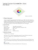
Push Button Dual Color DT8 DALI Controller 09.2402K8CTGS.04766
Click to switch on group.
11 mm
Function introduction
Important: Read All Instructions Prior to Installation
Front side
Back side
Output DALI signal
Operation Current 4mA
Operating temperature 0-40°C
Relative humidity 8% to 80%
Dimensions 71.2x71.2x13.6mm
Product Data
Power Supply Supply By DALI Bus
Click to switch off group.
Click to adjust color temperature
to the warmest. Press and hold
down to get warmer and warmer
white
Click to adjust color temperature
to the coolest. Press and hold
down to get cooler and cooler
white
D1 D2
DALI INPUT
Rotary Switch for Assigning
Group (Total 16 Groups)
DALI signal output
Wiring Diagram
DALI signal
D1
D2
DALI Bus
L
N
GV+
V-
OUTPUT
INPUT
AC Power
50/60Hz
12V/24V/36V
CV PSU
V+ V+
WW WW
CW CW
WW WW
CW CW
Conne ct with Dual C olo r LED Strip
DT8 DALI CCT Dimm er
0-6 0 -9
LED O UTPUT
12- 36V DC
POW ER INPU T
V-
V-
V+
V+
+
WW-
CW-
WW-
CW-
D1
D2
D1
D2
DAL I SIGNA L
V+ V+
WW WW
CW CW
WW WW
CW CW
Conne ct with Dual C olo r LED Strip
DT8 DALI CCT Dimm er
0-6 0 -9
LED O UTPUT
12- 36V DC
POW ER INPU T
V-
V-
V+
V+
+
WW-
CW-
WW-
CW-
D1
D2
D1
D2
DAL I SIGNA L
V+ V+
WW WW
CW CW
WW WW
CW CW
Conne ct with Dual C olo r LED Strip
DT8 DALI CCT Dimm er
0-6 0 -9
LED O UTPUT
12- 36V DC
POW ER INPU T
V-
V-
V+
V+
+
WW-
CW-
WW-
CW-
D1
D2
D1
D2
DAL I SIGNA L
WW CW
S1 S2
Press and hold down to turn
up brightness of group.
Press and hold down to turn
down brightness of group.
Scene Button 1, click to recall
predefined or saved Scene of
selected Group, press and hold
down to save scene to selected
Group
Scene Button 2, click to recall
predefined or saved Scene of
selected Group, press and hold
down to save scene to selected
Group
Scene
Rotary Switch for Assigning
Scene (Total 16 Scenes)

Mounting
The key part of this controller is a universal, standard switch element that can be integrated in numerous
frames by different manufactures as below list:
BEKER S1, B1, B3, B7 glass
GIRA Standard55, E2, Event, Esprit
JUNG A500, Aplus
MERTEN M-smart, M-Arc, M-Plan
1. This controller is a DALI DT8 push button control panel that enables smooth color adjustment of dual color
(Warm White and Cool White) LED lighting. It controls DALI DT8 devices and can be compatible with DALI
masters that supports DT8 commands.
2. Do wiring according to connection diagram correctly.
3. Set starting Group number via rotary switch on the back: (0-15 selectable)
• This DALI push button controller enables dimming commands and DT8 commands to be sent to One Group of
devices on the DALI circuit by one Group of buttons. A rotary switch on the back is used to select Group you
would like to control and set the starting Group number, and total 16 Groups (0-15) can be selected.
• When the rotary switch arrow position is at 0, Group 1 of buttons controls all 16 Groups of devices through
broadcast.
• When the rotary switch arrow position is at X except 0 (1-15), Group 1 of buttons controls Group X-1 of
devices.
For example: Rotary switch arrow at 1, Group 1 of buttons controls Group 0 of devices. Rotary switch arrow at
15, Group 1 of buttons controls Group 14 of devices.
Please refer to the detailed Group setting table as follows:
• DO NOT installed with power applied to device.
• DO NOT expose the device to moisture.
Safety & Warnings
Rotary Switch
Position
DALI Group for
Group 1 ofButtons
0
Broadcast
1
0
2
1
3
2
4
3
5
4
6
5
7
6
8
7
9
8
10
9
11
10
12
11
13
12
14
13
15
14
Operation
4. Set starting Scene number via rotary switch on the back: (0-15 selectable)
• This DALI push button controller enables Scene selection commands for up to two Scenes to be sent to the
DALI circuit by two Scene buttons S1, S2. A rotary switch on the back is used to select Scenes you would like to
control and set the starting scene number, and total 16 Scenes (0-15) can be selected.
• When the rotary switch arrow position is at X (0-15), Scene button S1 controls Scene X, and S2 controls
Scene X+1.
For example: Rotary switch arrow at 0, button S1 controls Scene 0, and S2 controls Scene 1. Rotary switch
arrow at 15, button S1 controls Scene 15, and S2 controls Scene 0.
Please refer to the detailed Scene setting table as follows:
Rotary Switch
Position
Scene assigned
to S1
0 1 2 3 4 5 6 7 8 9 10 11 12 13 14 15
0 1 2 3 4 5 6 7 8 9 10 11 12 13 14 15
Scene assigned
to S2 1 2 3 4 5 6 7 8 9 10 11 12 13 14 15 0
5. Save Scenes
Turn on the DALI panel →
Press and hold down button WW/CW to select a color →
Press and hold down button S1/S2 until the LED lights connected with DALI device flash, which indicates the
scene is saved successfully.
Note: The saved scenes will cover the predefined ones.
/