
1252-050202—SNAP-IT-RM Installation Guide 1
Chapter 1
SNAP-IT-RM Installation Guide
Introduction
The Opto 22 SNAP-IT™ rack-mount unit is a packaged solution for attaching electrical, electronic,
and mechanical devices to a wired Ethernet network or a wireless LAN. Once attached to a
network through the SNAP-IT unit, these devices can be monitored and controlled from anywhere
in the world.
The rack-mount unit includes a SNAP Ethernet brain or SNAP Ultimate brain, a 16-module
mounting rack, and a power supply, all built in and already wired. The SNAP Ultimate brain adds
programming capability; with it you receive ioControl™ software, an easy-to-use flowchart-based
environment for developing machine and process control applications.
For any SNAP-IT model, you add the input/output (I/O) modules that are necessary for your
application.
Packaged in a 3U box, SNAP-IT units can be placed on a desktop or table or mounted on a
standard 19-inch rack. Typical applications include monitoring facilities, computer, and
telecommunications equipment, as well as mobile equipment and machines. For example, using
SNAP-IT units built to your specifications, you can:
• Acquire data from mobile test equipment for immediate network access
• Monitor alarms and doors
• Control fans, lights, pumps, and compressors
• Monitor equipment line voltage and current draw
• Report production counts
• Detect machine jams and shutdowns
• Track machine throughput to plan preventive maintenance
• Control temperature, humidity, and security in facilities
• Remotely reboot servers.
The SNAP-IT unit requires no special software or programming. You can easily configure
modules and manage devices using any authorized computer and included software. If you need

INTRODUCTION
2 1252-050202—SNAP-IT-RM Installation Guide
programming capability, a unit with a SNAP Ultimate brain provides the control capability and
the software to easily build your own control programs.
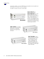
The SNAP-IT rack-mount unit comes in several models:
SNAP-IT-RM-ADS (with a
SNAP Ethernet brain) and
SNAP-IT-RM-UADS (with a SNAP
Ultimate brain) can use analog,
digital, and special-purpose modules
(such as serial communication
modules). The first eight positions in
the rack accommodate digital, analog,
or special-purpose modules; the last
eight positions accommodate analog
or special-purpose modules.
SNAP-IT-RM-D64 uses standard
digital modules only, providing up to
64 I/O points on a 16-module
digital-only rack. Digital features
are limited.
SNAP-IT-RM-UM16 includes a
SNAP Ultimate brain that handles
up to 64 mixed I/O points. The
special 16-module rack allows
analog, standard digital, and
special-purpose modules to be
placed in any module position. As
with the digital-only model, digital
features are limited.
SNAP-IT-RM-ADS
or
SNAP-IT-RM-UADS
SNAP-IT-RM-D64
SNAP-IT-RM-UM16

INTRODUCTION
1252-050202—SNAP-IT-RM Installation Guide 3
What’s in this Guide?
This brief guide shows you how to insert modules in the unit and mount the unit.
For all models except SNAP-IT-RM-UADS and SNAP-IT-RM-UM16—To configure
modules and communicate with the unit, you will also need Opto 22 form #1460, the SNAP
Ethernet-Based I/O Units User’s Guide, included in this binder.
For SNAP-IT-RM-UADS or SNAP-IT-RM-UM16—To configure modules and write control
programs for the unit, you will also need the following Opto 22 forms:
• #1460, the SNAP Ethernet-Based I/O Units User’s Guide
• #1440, the ioManager User’s Guide
• #1300, the ioControl User’s Guide
• #1301, the ioControl Command Reference
• #1314, the ioControl Commands Quick Reference Card
Forms #1460 and #1440 are included in this binder. The other forms are in Adobe® Acrobat® PDF
format on the CD that came with your SNAP-IT unit. They are also available on our Web site at
www.opto22.com. (The easiest way to find a form is to search on its form number.)
For all SNAP-IT-RM units—Wiring information and specifications for modules can be found
in the Opto 22 documents listed below. All are included in this binder and are also available in
Adobe Acrobat PDF form on the Opto 22 Web site at www.opto22.com.
For Help
If you have problems installing or using your SNAP-IT unit and cannot find the help you need in
the product guides, you can contact Opto 22 Product Support.
Phone: 800-TEK-OPTO (835-6786)
951-695-3080
(Hours are Monday through Friday,
7 a.m. to 5 p.m. Pacific Time)
Fax: 951-695-3017
Email: [email protected]
Opto 22 Web site: support.opto22.com
Digital input modules Form #773
Digital output modules Form #1144
Analog input modules Form #1065
Isolated analog input modules Form #1182
Analog output modules Form #1066
Serial communication modules Form #1191
NOTE: Email messages
and phone calls to
Opto 22 Product Support
are grouped together and
answered in the order
received; neither takes
priority.

QUICK START
4 1252-050202—SNAP-IT-RM Installation Guide
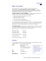
Quick Start
The following diagram shows the parts inside the SNAP-IT rack-mount unit and how modules are
inserted from the back. This diagram shows the SNAP-IT-RM-ADS model. The other models are
similar, except that some have additional LEDs on the front panel.
About Modules
Input/output (I/O) modules are sold separately from the SNAP-IT unit so you can choose the
modules you need from the wide variety available. Modules come in three basic types:
•Digital modules monitor and control electrical, mechanical, and electronic devices that
can be in one of only two states: either on or off. Dry contacts and door sensors are
examples of digital devices. Standard digital modules contain four points. These points are
used either as inputs to report a device’s on/off status, or as outputs to turn a device on
and off remotely. Standard digital modules can be placed in any of the first eight positions
on the rack.
•Analog modules, used with all models except the SNAP-IT-RM-D64, monitor devices that
have a range of possible values, such as temperature or pressure sensors. Analog modules
contain either two or four input or output points.
•Special-purpose modules provide specific functionality. Special-purpose modules can
be placed in any position on the rack; check the module’s data sheet for limitations on the
total number of modules on a rack.
–Serial modules communicate with serial devices, such as chart recorders, barcode
readers, and security devices, by sending and receiving ASCII characters via a serial
port. Each module has two serial ports.
–High-density digital modules offer 32 digital points in a compact input or output
module. Each module contains four banks of eight points. High-speed counting is not
available, and points within each bank are not isolated from each other. These modules
are ideal for applications in confined space where isolation and high-speed counting
are not required.

QUICK START
1252-050202—SNAP-IT-RM Installation Guide 5
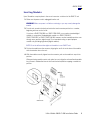
Inserting Modules
Up to 16 modules snap into place in the row of connectors on the back of the SNAP-IT unit.
1. Make sure the power cord is unplugged from the unit.
WARNING: Make sure power is off before continuing, or you may severely damage the
module.
2. Turn the unit around to the back and notice that each connector position has a number,
beginning with zero on the far left.
If you have a SNAP-IT-RM-D64 or a SNAP-IT-RM-UM16, you can place standard digital
modules in any position.Standard digital modules in a SNAP-IT-RM-ADS,
SNAP-IT-RM-UADS, or SNAP-IT-RM-FH-WLAN, however, must be inserted in positions zero
through seven; positions eight through 15 accommodate analog or special-purpose
modules only (including high-density digital modules).
NOTE: Do not install more than eight serial modules in one SNAP-IT unit.
3. Position the module over the connector, aligning the small slot at the base of the module
with the retention bar on the rack.
4. With the module correctly aligned over the connector, push on the module to snap it into
position.
When positioning modules next to each other, be sure to align the male and female module
keys (shown in the detailed view in the illustration below) before snapping a module into
position.

QUICK START
6 1252-050202—SNAP-IT-RM Installation Guide
Modules snap securely into place and require a special tool (provided) to remove them. If
you need to remove a module, see page 10.
NOTE: Modules can be secured with hold-down screws if needed. See page 7 for
instructions.
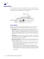
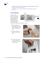
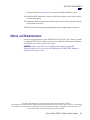
Inserting Blanks
If you do not install
modules in all the module
positions, use the plastic
blanks provided to cover
empty module postions.
These blanks provide a
finger guard for the back of
the unit. Blanks can be
easily removed if additional modules need to be added.
1. Break off the number of
blanks needed for the number
of empty module positions, as
shown in the photograph at
right.
2. Use pliers to snap off any
extra plastic nubs from the
blanks.
3. To insert a blank, fit the slot
on its lower end over one
edge of the unit’s back plate
as shown at right.
Empty module positions covered with blanks
Modules

QUICK START
1252-050202—SNAP-IT-RM Installation Guide 7
4. Lifting the handle in the middle
of the blank with one hand,
push the upper end so its slot
fits over the other edge of the
back plate, as shown. Repeat
with each blank, making sure
both ends of each blank are
securely in position.
NOTE: To remove a blank, simply
pull it out by the handle.
When all modules and blanks
are in position, the unit is ready for placement or mounting.
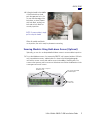
Securing Modules Using Hold-down Screws (Optional)
Optionally, you can also use the provided hold-down screws to secure modules in position.
1. To use the hold-down screws, first remove the SNAP-IT unit’s antenna (wireless LAN units
only), top and bottom covers, and back plate. As shown in the following photograph,
unscrew four screws on each side and one screw in the middle of the back plate, four
screws on the top cover, and four screws on the bottom cover. Notice the differences in the
screw types and save all screws.
Four screws
on each side
Four screws each on top cover
and bottom cover One screw in the middle
of the back plate

QUICK START
8 1252-050202—SNAP-IT-RM Installation Guide
2. Slide the top and bottom covers
off; then remove the back plate.
Use the hold-down screws to
secure both sides of each module,
as shown at right.
CAUTION: Do NOT over-torque
screws.
3. When all modules are secured,
replace the back plate and top and
bottom covers. Replace the
screws you removed in step 1,
making sure the correct screw
type is in the proper location.
4. IMPORTANT: If some module
positions are empty, use the
plastic blanks provided to cover
the empty positions. See page 6
for instructions.
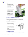
Mounting the SNAP-IT Unit (Optional)
The unit can be placed on a desktop or table, or it can be mounted on a standard 19-inch rack.
Modules are inserted at the back of the unit, and wiring to the devices being managed is
attached to pluggable connectors at the back of each module. Choose a position that allows rear
access.
To mount the unit on a rack, follow these steps:
1. To attach rackmount brackets,
position brackets at the back of the
unit’s sides as shown in the diagram
at right.
2. With nuts in the top and bottom slots,
slide the brackets down the unit’s
sides until they are flush with the
front of the unit. Tighten screws
securely.
3. With top and bottom covers and back
plate in place, insert the power cord.
WARNING: Electrical hazard!
Do not plug in the unit unless top and bottom covers and back plate are securely in place.

SPECIFICATIONS
1252-050202—SNAP-IT-RM Installation Guide 9
4. Mount the SNAP-IT unit on the rack.
5. Plug the wiring connector into each module to attach modules to the devices they monitor.
Using the SNAP-IT Unit on the Network
Follow instructions in the ioManager User’s Guide to do the following:
1. Assign an IP address to the SNAP-IT unit.
2. Test communication.
3. Configure I/O points and features.
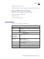
Specifications
The following table lists specifications for SNAP-IT units.
Communications
Protocols SNMP, SMTP, FTP, and Modbus/TCP over TCP/IP, UDP/IP, and PPP
Serial Port RS-232. Default rate is 19,200 Kbd; baud rate is soft-selectable from 2400
to 115,200 Kbd.
Ethernet Port 10/100 Mbps Fast Ethernet, using Category 5 or superior solid UTP cable
with RJ-45 connector
Other Specifications
Dimensions
(SNAP-IT-RM-ADS,
SNAP-IT-RM-UADS,
SNAP-IT-RM-D64, and
SNAP-IT-RM-UM16)
19-inch rack-mount enclosure, 3U. 17.35" W, 5.22" H, 7.125" D (box only;
8.125" with modules)
Power Supply UL rated 120–250 VAC
Manufacturer rated 100–250 VAC
(Other options available by special order.)
Power Cord (Ordered separately) 120 VAC United States, 240 VAC United Kingdom,
or 240 VAC International
Power Consumption 30 W
Temperature 0° to 55° C operating, -30° to 85° C storage
Humidity 0–95% humidity, non-condensing

REMOVING A MODULE
10 1252-050202—SNAP-IT-RM Installation Guide
LED Indicators
The following table describes system LEDs located on the front of the SNAP-IT unit.
LEDs for Standard Digital I/O Modules
In addition to the system LEDs shown in the table above, LEDs are also provided to indicate the
status of individual digital points. A lighted LED indicates that the digital point is on. Four LEDs
are provided per module. (If an analog, serial, or high-density digital module is in one of the
module positions, the LEDs do not function.)
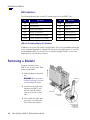
Removing a Module
To remove a module from the
SNAP-IT unit, you will use the SNAP
module tool (provided).
1. Unplug the power cord from the
unit.
WARNING: Make sure power is
off before continuing, or you may
severely damage the module.
2. Unscrew the four small screws
holding on the SNAP-IT unit’s
top cover. Carefully slide the
cover out of the slots on each
side.
3. If the modules are held in place
with screws, also remove the
unit’s bottom cover and back
LED Description LED Description
ACT Network Activity RUN Normal Operation
FD Full Duplex Mode 3VF 3 Volt Fault
ERD Ethernet—Receive Data 5VF 5 Volt Fault
ETD Ethernet—Transmit Data FLT Microprocessor Fault
10MB Ethernet Link Detection at 10 Mbps SRD Serial—Receive Data
100MB Ethernet Link Detection at 100 Mbps STD Serial—Transmit Data

NOTES ON MAINTENANCE
1252-050202—SNAP-IT-RM Installation Guide 11
plate (see the illustration on page 7). Then remove the module’s hold-down screws.
4. Holding the SNAP module tool as shown in the illustration above, insert it into the notch at
the base of the module.
5. Squeeze the module tool against the module to open the release latch, and pull straight up
on the module to remove it.
6. When you have finished removing and replacing modules, plug the power cord back in.
Notes on Maintenance
Instructions for maintenance are in the SNAP Ethernet-Based I/O Units User’s Guide. If you need
to change the SNAP-IT unit’s IP address, reset it to factory defaults, or download new firmware,
you will need to use instructions in the user’s guide.
CAUTION: Jumpers in the SNAP-IT unit are different from jumpers on other SNAP
Ethernet-based brains. Be sure to follow the “Modified Brain for SNAP-IT-RM” diagram to
determine which jumper is which.
Copyright © 1999–2005 Opto 22. All rights reserved. Printed in the United States of America.
The information in this manual has been checked carefully and is believed to be accurate; however, Opto 22 assumes no responsibility
for possible inaccuracies or omissions. Specifications are subject to change without notice. All trademarks, trade names, logos, and
service marks referenced herein belong to their respective companies.

NOTES ON MAINTENANCE
12 1252-050202—SNAP-IT-RM Installation Guide
-
 1
1
-
 2
2
-
 3
3
-
 4
4
-
 5
5
-
 6
6
-
 7
7
-
 8
8
-
 9
9
-
 10
10
-
 11
11
-
 12
12


Ask a question and I''ll find the answer in the document
Finding information in a document is now easier with AI
Related papers
-
OPTO 22 SNAP-IT-PM Installation guide
-
-
-
Allen-Bradley DF1 User manual
-
-
-
-
-
-
Other documents
-
-
-
Vestil SWA-60-AW Owner's manual
-
IFM CR2042 Owner's manual
-
AMX AXD-MCP/PB User manual
-
ABB S800 User manual
-
Agilent Technologies 6610XA User manual
-
Dante DFG480000 Frame Operating instructions
-
Nexus 1250 Installation & Operation Manual
-
Motorola MTR2000 Operating instructions