Page is loading ...

DFG48000
Ethernet Managed Switch
Installation and Operations Manual
Model Number: DFG480000 Frame
DFG48044XEYRC
DFG48044XFYRC
DFG48G022XEYRL
DFG48G024XEYRL
Description: Fiber Optic Ethernet Managed Switch

Table of contents DFG48000 Managed Fiber Switch Page
DFG48000 Managed Fiber Optic Switch 3
Hardware Installation and User Guide 3
Federal Communications Commission 3
1.0 SPECIFICATIONS 4
1.1 Technical Specifications 4
Operating Environment 5
Power Supply (Internal) 5
Agency Approvals 6
1.2 Ordering Information 6
DFG48000 Managed Fiber Switch, base unit 6
Configuration Options 6
2.0 INTRODUCTION 7
2.2 Product Description – DFG48000 Managed Fiber Switch 7
2.2.1 DFG48000 and DFG48000R chassis 8
2.2.7 Four-Port 10 Mb MM Fiber ST Modules 9
2.2.8 Gigabit (1000Mbps) port modules 10
2.2.9 Packet Prioritization, 802.1p QOS 11
2.2.10 Frame Buffering and Flow Control 11
2.2.11 Managed Network Software for DFG48000-Series 12
2.3 Features and Benefits 12
Standard AC power input 100-240VAC 12
DFG48000 licensed Network Management Software 12
2.4 Applications 13
3.0 Installation 14
3.1 Locating DFG48000 Switches 14
3.2 Connecting Ethernet Media 15
3.2.2 Connecting Fiber Optic SC-type, "Snap-In" 15
3.2.3 Connecting Single-Mode Fiber Optic 15
3.2.5 Connecting Twisted Pair (CAT5E or better) 15
3.3 Table-Top or Shelf Mounting 16
3.3.1 Rack-mounting 17
3.4 Powering the DFG48000 Managed Fiber Switch 18
3.4.1 Alarm Contacts for monitoring internal power, and Software Traps 18
3.5 DFG480XX (Port Module) Card Installation 18
3.5.1 Preparation for Installing and Removing DFG48000 19
3.6 Connecting the Console Terminal to DFG48000 (Management) 22
3.6.1 RS-232 (DB-9) Console Com port (Serial port) pin assignments 23
4.0 OPERATION 24
4.1 Switching Functionality 24
Address Learning 24
4.2 Status LEDs 24
4.3 Up-link MDI-MDIX on RJ-45 port modules, for port 1 only 24
4.4 Auto-Cross (MDIX) and Auto-negotiation, for RJ-45 ports 24
4.5 Flow-control, IEEE 802.3x standard 25
5.0 Introduction - DFG48000 Managed Fiber Switch Port Modules 26
5.2 DFG480XX Card (Port Module) Description 26
5.2.3 DFG48044EYRC 4@ 10/100Mbps RJ-45 Ports & 2@100Mbps single-mode FX-SC-type 20Km 28
5.2.4 DFG48044FYRC 4@ 10/100Mbps RJ-45 Ports & 2@100Mbps single-mode FX-SC-type 40Km 28
5.2.5 DFG48G024EYRL 2@ 10/100/1000Mbps RJ-45 & 2@100Mb single-mode FX, LC small form 29
5.2.6 DFG48G022EYRL 2@ 10/100/1000Mbps RJ-45 & 1@100Mb single-mode FX, LC small form 29
6.0 TROUBLESHOOTING 30
6.3 Return Material Authorization (RMA) Procedure 31
6.4 Shipping and Packaging Information 31
APPENDIX A: WARRANTY INFORMATION 31

Hardware
Installation and User Guide
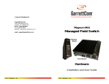
DFG48000
Managed Fiber Optic Switch
Hardware
Installation and User Guide
Trademarks
Ethernet is a trademark of Xerox Corporation
NEBS is a trademark of Telcordia Technologies
UL is a registered trademark of Underwriters Laboratories
Important: The DFG48000 Managed Fiber Switch contains no user serviceable parts. Attempted
service by unauthorized personnel shall render all warranties null and void. If problems are
experienced with DFG48000 Switch products, consult Section 6 - Troubleshooting, of this User
Guide.
Copyright © 2007 Dante Security, Inc. All rights reserved. No part of this publication may be
reproduced without prior written permission from Dante Security, Inc.
Contacting Dante Security, Inc
Please use the mailing address, phone and fax numbers and email address listed below:
Dante Security, Inc.
1150 Broadway, suite 210
Hewlett, NY 11234, USA
Phone (516) 213-4917
Website: http://www.dantesecurity.com
Email: support@danteSecurity.com
Federal Communications Commission
Radio Frequency Interference Statement
This equipment generates, uses and can radiate frequency energy and if
not installed and used properly, that is in strict accordance with the manufacturer's
instructions, may cause interference to radio communication. It has been tested
and found to comply with the limits for a Class A computing device in accordance
with the specifications in Subpart J of Part 15 of FCC rules, which are designed to
provide reasonable protection against such interference when operated in a
commercial environment. Operation of this equipment in a residential area is
likely to cause interference, in which case the user at his own expense will be
required to take whatever measures may be required to correct the interference.
Canadian Emission
This Class A digital apparatus meets all requirements of the Canadian
Interference-Causing Equipment Regulations.
Cet appareil respecte toutes les exigences du Réglement sur le matériel du
Canada. Cet appareil est Classe A..

1.0 SPECIFICATIONS
1.1 Technical Specifications
Performance
Filtering / Forwarding Rate:
Ethernet: 14,880 pps
Fast Ethernet: 148,800 pps
Gigabit Ethernet: 1, 488,000 pps
Switching Processing Type: Store and Forward with IEEE 802.3x full duplex
Flow -control, non-blocking
Data Rate: 10Mbps, 100Mbps and 1000Mbps
Address Table Capacity: 4K node, self-learning with address aging
Packet buffer size: 240KB for 10/100 and 120KB for 1000Mb
Latency: 5 µs + packet time (100 to 100Mbps)
15 µs + packet time (10 to 10 Mbps, and 10 to 100Mbps)
Network Standards and Compliance, hardware
Ethernet V1.0/V2.0 IEEE 802.3: 10BASE-T,
IEEE 802.3u: 100Base-TX, 100BASE-FX
IEEE 802.3z: 1000BASE-X Ethernet (Auto-negotiation)
IEEE 802.3ab: 1000BASE-X Ethernet
IEEE 802.1p: Priority protocol
IEEE 802.1d: Spanning tree protocol
IEEE 802.1w: Rapid Spanning tree protocol
IEEE 802.1q: VLAN Tagging
IEEE 802.3x: Flow Control
Maximum 10 Mbps Ethernet Segment Lengths
Unshielded twisted pair - 100 m (328 ft)
Shielded twisted pair - 150 m (492 ft)
10BASE-FL multi-mode fiber optic - 2 km (6,562 ft)
10BASE-FL single-mode fiber optic - 10 km (32,810 ft)
Maximum Standard Fast Ethernet Segment Lengths:
10BASE-T (CAT 3, 4, 5 UTP) - 100 m (328 ft)
100BASE-TX (CAT 5 UTP) - 100 m (328 ft)
Shielded twisted pair - 150 m (492 ft)
100BASE-FX, half-duplex, multi-mode - 412 m (1350 ft)
100BASE-FX, full-duplex, multi-mode - 2.0 km (6,562 ft)
100BASE-FX, half-duplex, single-mode - 412 m (1350 ft)
100BASE-FX, full-duplex, single-mode - 20.0 km (66K25 ft)
100BASE-FX, full-duplex, Long Reach - 40.0 km (122K ft)
Maximum Standard Gigabit Ethernet Segment Lengths:
1000BASE-T (CAT5E or higher is recommended) - 100 m (328 ft)
1000BASE-SX, full-duplex, multi-mode (62.5µm cable) - 220m
1000BASE-SX, full-duplex, multi-mode (50µm cable) - 550m
1000BASE-LX, full-duplex, single-mode (62.5µm cable) -5Km

Fiber Multi-mode connector types supported:
Fiber Port, SC-type (snap-in): Fiber optic multi-mode, 100BASE-FX
Fiber Single-mode connector types:
Fiber Port, SC-type: Fiber optic single-mode, 100BASE-FX
Fiber Port, LC-type Fiber SFF single-mode, 100BASE-FX
LEDs: Per Port
LK: Steady ON when media link is operational
ACT: ON with receiver port activity
FDX/HDX: ON = Full-Duplex Mode
OFF = Half-Duplex Mode
100/10: ON = 100Mbps speed
OFF = 10 Mbps
Operating Environment
UL 60950 “Component Parts” temp. rating: 130° F (55°C)
IEC 60068 “Type Test” rating: -40°to 185°F (-40°to 85°C)
Storage: -40°to 185°F (-40°to 85°C)
Ambient Relative Humidity: 5% to 95% (non-condensing)
Altitude: -200 to 13,000 ft. (-60 to 4000m)
Conformal Coating option on Z models
Packaging
Enclosure: Rugged High strength metal. Suitable for stand-alone
or rack-mounting
Dimensions: 1.70in. H x 17.0in. W x 9.0in. D
4.32cm H x 43.2cm W x 22.9cm D
Cooling method: Fan cooled, @ 3@ 7 cfm ea.
Management Console connector
DB-9 for RS-232 “null-modem “cable (sometimes called an Xmodem cable)
Power Supply (Internal)
AC Power Connector: IEC-type, male recessed at rear of chassis,
with adjacent manual ON-OFF switch (on AC models only)
Input Voltage: 100 to 240 VAC (auto-ranging)
Input Frequency: 47 to 63 Hz (auto-ranging)
Power Consumption: 55 watts typical
60 watts max (for a fully loaded fiber model)
35 watts for a fully-loaded copper only model

Per-port MDI or MDIX on RJ-45 the copper daughter board has MDI-MDIX Auto-crossover on all the RJ-
45 ports and eliminate the use of cross-over cable between the devices. Also port specific user settings
(such as FDX or HDX, copper 10/100 speed) can be fixed using software commands. Alarm Contact
Optional) Alarm Contact option is offered as a configuration option. The two alarm contacts are SPST NC
Form-C relays, and an open condition indicates abnormal status. The Hardware Alarm monitors internal
power on the main board, and the Software Alarm is activated by one or more user-selected software
traps.
Agency Approvals
UL listed (UL60950), cUL, CE, Emissions meet FCC Part 15 Class A
NEBS Level 3 and ETSI Certified for Carrier Central Offices
IEEE 1613 Class 2 Environmental Standard for Electric Power Substations
See also Note for Power Substations in Section 3.2.4, 3.6.1, and 5.2.9 IEC 61850 EMC and Operating
Conditions Class C for Power Substations
Warranty: Two years, return to factory Made in USA NEBS Testing and Certification: NEBS certified
1.2 Ordering Information
MODEL DESCRIPTION
DFG48000 Managed Fiber Switch, base unit
May be configured with a selection of 10/100/1000 DFG480XX fiber and copper port connector types.
Wire speed filtering and forwarding across all ports, 802.3x flow control, 802.1p priority packet
processing, self-learning 4K-node address table, large 240KB packet buffers for 10/100 and 120KB for
1000Mb. Plug-and-play switching services, front-mounted LEDs, internal auto-ranging AC power supply,
19" rack-mounting brackets. For licensed managed networks software, see MNS materials. DFG48000R:
“Reverse” model, same as Model DFG48000 except the user ports and the power input connectors are in
the rear. Two sets of LEDs (both rear and front) provide duplicate status data for viewing from either
side.
Configuration Options:
Each DFG48000 frame unit has four port module slots. The first three (A, B, C) may be one of the
modules DFG480XX below; one (slot D) may only be a Gigabit module DFG48G0XX. Select up to four
port modules per base unit.
DFG48044XEYRC Ethernet Switch 10/100Mbps 4 Copper, 4 Fiber Ports TRX 20Km SM SC
DFG48044XFYRC Ethernet Switch 10/100Mbps 4 Copper, 4 Fiber Ports TRX 40Km SM SC
DFG48G022XEYRL Ethernet Switch 10/100/1000Mbps 2 Copper, 2 Fiber Ports TRX 20Km SM LC
DFG48G024XFYRC Ethernet Switch 10/100/1000Mbps 2 Copper, 4 Fiber Ports TRX 20Km SM LC
Y=-10°
~
+55C°, Z=-40°
~
+74C° (includes conformal coating)

2.0 INTRODUCTION
2.1 Inspecting the Package and Product
Examine the shipping container for obvious damage prior to installing this product; notify the carrier
of any damage that you believe occurred during shipment or delivery. Inspect the contents of this
package for any signs of damage and ensure that the items listed below are included. This package
should contain:
1 DFG48000 Managed Fiber Switch, base unit (configured with user-selected port module options)
1 AC Power Cord (U.S. only) 1 Set of metal “Ears” for 19” rack mounting 1 Installation and User
Guide (this manual) 1 Product Registration Card Remove the items from the shipping container. Be
sure to keep the shipping container should you need to re-ship the unit at a later date. To validate
the product warranty, please complete and return the enclosed Product Registration Card to Dante
Security, Inc. as soon as possible. In the event there are items missing or damaged, contact the
party from whom you purchased the product. If the unit needs to be returned, please use the original
shipping container if possible. Refer to Section 6, troubleshooting, for specific return procedures.
2.2 Product Description – DFG48000 Managed Fiber Switch
The DFG48000 Managed Fiber Switch boosts the performance of large Ethernet LANs, typically
serving as a “backbone” switch. It has the flexibility to handle a mix of both fiber and twisted-pair
switched ports along with Gigabit backbone port options. Industry-standard IEEE 802.1p QOS
prioritization is included, providing high performance switching services for both “smooth” streaming
and “bursty” data traffic. The DFG48000 has up to 25 ports capacity, all of which may be configured
as fiber ports, but still offers a space-saving rack-mount chassis that is only 1U (1.70in. or 4.32cm)
high. The “mixed-media” capability allows user selection of all popular flavors of fiber port connectors
and modes, including even 10 Mb fibers along with Gigabit ports. It also allows a mix of 10/100Mb
RJ-45 (copper) ports and a fiber Gigabit port in the same unit. This flexibility is achieved via a family
of DFG480XX port modules for copper and fiber-built-in (emphasizing Small Form Factor fiber for high
fiber port density), 6-port modules for fiber and RJ-45 combinations, and 1 GB port module selections
using GBICs. These modules can be factory configured in a base chassis unit (or may be changed in
the field by trained technicians) to adapt the unit to the user’s application and Ethernet cabling
requirements. Even evolving mixed-media requirements for 10Mb and 100Mb fiber and copper as well
as Gigabit ports can be handled by the DFG48000 product.
The chassis mounting rack style may be “regular” (with the ports and LEDs in the front and the power
input and management console connector in the rear) or “Reverse” (with the ports and LEDs and the
power-input and the management console connector all in the rear and a duplicate set of LEDs in the
front). Rack widths accommodated include standard 19” and input power may be AC. Designed for
use in network traffic centers, the DFG48000 Managed Fiber Switches are easy to install and use.
Addresses of attached nodes are automatically learned, maintained and aged out, adapting the
switching services to network changes. LEDs provide status information on each port. The DFG48000
provides high performance plug-and-play hardware operation, 802.1p packet prioritization in
hardware, and industry-standard managed networks software functionality in convenient 1U rack-
mount packages.

\
2.2.1 DFG48000 and DFG48000R chassis
The DFG48000 is a 19” rack-mountable Ethernet Switch with three eight port slots (A, B, and C) and
one Gb-only slot (D) for configuration flexibility. Slots A, B and C may be configured with any of a
large selection of fiber and copper port types and combinations of types, typically eight ports per
module, but sometimes 6 or 4 ports or even one Gb port. Slot D may be configured with a Gb module
that accepts GBICs. The port types configurable using the 4 slots allows the DFG48000 to efficiently
serve a large variety of applications, especially using fiber media. The DFG480XX port modules are
normally factory installed, but may be changed or added in the field. (See Section 5)
Figure 2.2.1a: “Regular” DFG48000 front view, configured for 24 + 1 GB ports Status LEDs are part
of each port module and are viewable when connecting the Ethernet media. A “regular” rack-mount
DFG48000 is shown in Figure 2.2.1a. On “Reverse” rack-mount models, there is a duplicate set of
LEDs on the other (front) side for normal status viewing from that direction. Of course, with
management, the port status data is also available in software.

The DFG480XX Combo six-port modules are also available with 4@ MTRJ 100Mb mm SFF fiber and
2@10Mb fiber mm ST ports, and with 4@ RJ45 10/100 copper and 2@10Mb fiber mm ST ports.
The 4@ RJ-45 + 2@ 10 Mb ST operation of the SFF fiber and the RJ-45 half of the module is as
described for those port types above. For detailed information about 10Mb mm ST fiber half of the
module, please check section 2.2.5.
2.2.7 Four-Port 10 Mb MM Fiber ST Modules
The 4 port @10Mb ST fiber modules behave the same as the 8@100Mb ST fiber modules except
for the 10Mb speed. For ports numbering, ports 1, 2, 5, 6 are present, ports 3, 4. 7, 8 are not
present. The default setup on the 10Mb fiber module is half-duplex, which allows the DFG48000
Switch to connect to any 10Mb hub or media converter or almost any other device with a 10Mb
fiber Ethernet port. User mode control per port through the MNS software is the same as the
other DFG480XX modules. The fiber ports support fiber cabling distances according to the
10BASE-FL standard, i.e., 2km distance for multi-mode fiber. (Single-mode for up to 10Km
distance may be available as a special order configuration).

2.2.8 Gigabit (1000Mbps) port modules
The DFG48000 offered a wide option Gigabit speed with multiple choices for the modular slot.
While up to two Gigabit modules (maxm.) can be configured in the modular slot. The Gigabit port
option for the modular slot comes in couple of different configuration. The Giga port has been
offered as single Gigabit module comes in flavor of G+4(10/100 RJ-45 ports) or G+2 (100Mb fiber
ports) as shown below. 1@ 1000Mb Fiber SC + 2@ 100Mb SC.

The DFG480XX Modules provide a GBIC opening for insertion of industry-standard GBICs to provide
Gigabit (Gb) media flexibility. GBIC models are available for both multi-mode (550m) and single-
mode 20 and 40 km fiber options, and for Gigabit copper as well, with new models appearing often.
The 1000Mb Gigabit fiber-port modules on the DFG48000s are normally set (factory default) to
operate at AUTO mode for best fiber distance and performance. The 1000Mbps SC fiber-optic module
on the Gigabit -SX and Gigabit-LX 1@ 1000Mb Fiber SC + 4@10/ 100Mb transceivers are compatible
with the IEEE 802.3z Gigabit standards.
There are two LEDs mounted on each Gigabit port module. The Gigabit fiber port is by default
configured at AUTO mode, and can be fix at 1000Mbps speed full duplex mode at any times and has
LEDs that indicate LK (Link status) and ACT (receiving activity) on that port when lit.
2.2.9 Packet Prioritization, 802.1p QOS
Quality of Service means providing consistent predictable data delivery to users from datagram paths
that go all across a network. As a LAN device, the DFG48000 can do its part to prevent any QOS
degradation while it is handling Ethernet traffic through its ports and buffers. DFG48000 switching
hardware supports the IEEE 802.1p standard and fulfills its role in support of QOS, giving packet
processing priority to priority tagged packets according to the 802.1p standard. In addition to
hardware support for QOS, the MNS software (R2) supports two priority queues that can be shared
across the eight levels of defined packet priorities for application-specific priority control by the user
through software configuration settings.
2.2.10 Frame Buffering and Flow Control
DFG48000’s are store-and-forward switches. Each frame (or packet) is loaded into the Switch’s
memory and inspected before forwarding can occur. This technique ensures that all forwarded frames
are of a valid length and have the correct CRC, i.e., are good packets. This eliminates the propagation
of bad packets, enabling all of the available bandwidth to be used for valid information. While other
switching technologies (such as "cut-through" or” express") impose minimal frame latency, they will
also permit bad frames to propagate out to the Ethernet segments connected. The "cut-through"
technique permits collision fragment frames (which are a result of late collisions) to be forwarded
which add to the network traffic. Since there is no way to filter frames with a bad CRC (the entire
frame must be present in order for CRC to be calculated), the result of indiscriminate cut through
forwarding is greater traffic congestion, especially at peak activity. Since collisions and bad packets
are more likely when traffic is heavy, the result of store-and forward operation is that more
bandwidth is available for good packets when the traffic load is greatest. When the DFG48000 Switch
detects that its free buffer queue space is low, the Switch sends industry standard (full-duplex only)
PAUSE packets out to the devices sending packets to cause “flow control”. This tells the sending
devices to temporarily stop sending traffic, which allows a traffic catch-up to occur without dropping
packets. Then, normal packet buffering and processing resumes. This flow-control sequence occurs in
a small fraction of a second and is transparent to an observer. Another feature implemented in
DFG48000 Switches is a collision-based flow control mechanism (when operating at half-duplex only).
When the Switch detects that its free buffer queue space is low, the Switch prevents more frames
from entering by forcing a collision signal on all receiving half-duplex ports to stop incoming traffic.

2.2.11 Managed Network Software for DFG48000-Series
DFG48000-Series’s come with licensed Firmware (Rel 3.2), which allows to configure the DFG48000 as a
Managed Switch and other Software enabled features. For additional information see the DFG48000 -
Series Software User guide in PDF format, a separate document normally accessed via your web-browser
at www.dantesecurity.net
2.3 Features and Benefits
Managed switching for high performance Ethernet LANs
DFG48000 Switches provide non-blocking (all ports can run at full speed at once) performance with
standard Managed Networks Software included. They are typically used in LAN traffic centers with 16 to
24 100Mb ports and one or 2 Gigabit ports for backbone connections, where managed network services
are desired.
Switching services includes 802.1p QoS packet prioritization
The DFG48000 switching hardware supports QoS, giving packet processing priority to priority tagged
packets according to the IEEE 802.1p standard. For portand application-specific priorities, the QoS
software may be configured by the user.
Features Fiber-Built-In
DFG48000 Managed Fiber Switches are designed to naturally include fiber ports, and support mixes of
multi-mode and single-mode; 10 Mb, 100Mb and 1000Mb speed; full-and half-duplex; classic Small Form
Factor (SFF) and GBIC fiber connectors. RJ-45 10/100 ports can also be configured in the mix of port
types.
Modular design for port flexibility, in a 1U space-saving rack-mount package
The 1U DFG48000 chassis has 4 slots for port configurations. Family of 4, 6 or 8 port modules allows the
user to select the desired mix of port types & speeds. The port modules are normally factory installed
and tested, but may be changed in the field.
Rack-mounting may be standard or “reverse”, 19 inch or ETSI or 23” Telco
The standard rack mounting provides Ethernet ports and status LEDs in front, service connections (power
input and management console) in the rear. “Reverse” rack mounting provides status LEDs in front and
all cabling connections in the rear. Standard 19’ rack mount brackets are included, with ETSI and 23”
Telco optional.
Standard AC power input 100-240VAC
Standard AC power input is IEC plug, 100-240VAC auto-ranging for worldwide use.
Heavy-duty design for Industrial Ethernet and extended temperature operation
Fiber ports take more power than copper ports, but the Dante Security DFG48000 design provides for
this with heavy-duty components. The ambient temperature can be up to 55°C.
NEBS and ETSI tested and certified
The DFG48000 has been tested and certified for NEBS and ETSI. Request test reports.
DFG48000 licensed Network Management Software included, S-Ring optional
Release 2.3 (summer ’03) includes SNMP Switch Management with secure access control, RMON, CLI,
Port Security; Port Mirroring; Port Settings Control; Telnet, TFTP, FTP support, Spanning Tree Protocol,
RSTP, Web-based, multi-level QoS, Port- and tag-based VLANs, GVRP, IGMP Snooping, SNMPc GUI
support; Event Log; SNTP client for time-of-day; BootP and DHCP client for IP configuring, and password
security. Supplied and updated via Internet and GCI FTP Server.
RJ-45 ports are MDI/MDIX supported
The RJ-45 modules are equipped with MDI/MDIX capability to eliminate the use of cross-over cable. The
Auto-MDIX capability, allow the Dante Security DFG48000 to cascade any Hub, switches or media
converters with normal straight cable.

2.4 Applications
DFG48000 Fiber Switches offer high performance and modularity. They provide the flexibility of
100Mbps fiber and copper ports as well as Gigabit ports, with industry-standard LAN management
software. DFG48000 Switches are easily used in a variety of applications including MANs
(metropolitan area networks) client/server computing, secure VLAN- performance upgrades to
departmental networks, and LAN traffic centers require Gb backbone services. The performance
characteristic of the DFG48000 Switches enables them to inter-connect a series of subnets (one
subnet per DFG48000 Switch port) in a LAN traffic center. The subnet connections may be via fiber
or twisted pair cabling, 100Mbps or 10 Mbps speed, and full-or half-duplex mode. The mixed-media
capability is ideal for upgrading existing Ethernet LAN networks where existing cabling must be
accommodated. The fiber-built-in media capability is ideal for integrating future-proof fiber cabling
into the LAN structure.
Example 1: DFG48000 Switch for a VLAN application
Equipped with lots of useful features, the DFG48000 Managed switch is able to handle a VLAN
application and provide a security and performance in an Ethernet network center. A secure VLAN-
enabled network is simply an administratively configured broadcast domain. The network
administrator determines which ports and nodes are in which broadcast domains by setting
membership profiles for each of them. The DFG48000’s VLAN capability can be developed in several
types of Virtual LANs, such as Port-based VLANs, or Tag-based VLANs. In an office environment
where departments such as Finance, Engineering, R&D, and Marketing need to keep a secure LAN,
the DFG48000’s VLAN feature will prevent traffic cross-over among domains, and thus from keep
sensitive data and information controlled. The Managed DFG48000 equipped with VLANs capability
is ideal for any application where a secure VLAN to multiple departments is needed. The modularity
of the DFG48000 Managed Fiber Switch makes it an attractive choice for use in applications with
LAN connections to an organization’s multiple site offices. The different offices can be easily
connected together with the Fiber ports supported by the DFG48000 Switch. A main NT-server in a
secure area protected from earthquake or fire hazards can be connected to the full duplex Gigabit
Fiber port. Full-duplex future proof fiber media can easily connect long distance subnets and provide
a stable secure network to all applications. The SNMP management capability of the DFG48000
Switch helps create a database of all the network subnets to easily manage the network.
Example 2: DFG48000 in Ethernet Backbone
In another application, a managed switch is needed to provide an Ethernet backbone for a
diversified network with multiple subnets. The back bone consists of high speed LAN segments
supported by 100Mbps full-duplex future-proof fiber media to provide secure long distance LAN
connections. The entire network is sharing a higher bandwidth Gigabit-enabled data-mining server
for the vital database located in a separate secured building. The copper ports are required for
multiple subnets inside the building. The entire spread network will be manageable to provide easy,
detectable, uninterrupted support through a viewable SNMP monitor. The DFG48000 Managed Fiber
Switch equipped with the mix of copper and fiber ports provides an economical and seamless
solution to the requirements. The user-configurable DFG48000 provides an extra boost to the
network requirements by providing copper/fiber media along with the higher bandwidth support of
10/100 and 1000Mb. The user can utilize the SNMP feature equipped with VLAN, RMON, SNTP and
other standard managed LAN features to provide a secure and stable network.
The DFG48000 Managed Fiber Switch with mixed-media flexibility allows the users more than one
configuration alternative. The user has an advantage by fulfilling the present requirements as well
as benefiting from the multiple choices of modules to support future expansion as the network
evolves. The Gigabit port option boosts the bandwidth for high speed to support the peak traffic and
minimize congestion.

3.0 Installation
Before installing the equipment, it is necessary to take the following precautions:
1.) If the equipment is mounted in an enclosed or multiple rack assembly, the environmental
temperature around the equipment must be less than or equal to 50C.
2.) If the equipment is mounted in an enclosed or multiple rack assembly, adequate airflow must be
maintained for proper and safe operation.
3.) If the equipment is mounted in an enclosed or multiple rack system, placement of the equipment
must not overload or load unevenly the rack system.
4.) If the equipment is mounted in an enclosed or multiple rack assembly, verify the equipment’s
power requirements to prevent overloading of the building/s electrical circuits.
5.) If the equipment is mounted in an enclosed or multiple rack assembly verify that the equipment
has a reliable and uncompromised grounding path.
6.) CB-Circuit breakers of 10Amps should be shown on top of the Rack.
This section describes installation of the DFG48000 Switches, as well as connection of the various
Ethernet media types.
3.1 Locating DFG48000 Switches
The location of a Dante Security DFG480XX Switch is dependent on the physical layout of the
network. Typically the Switch is placed in a central wiring location where groups of network devices
need to be connected in order to communicate with each other. These Switches are typically rack
mounted in a wiring closet see Section 3.3.2 below), but because they have rubber feet they can also
be installed on a shelf or table top unit. The compact size allows it to be easily placed in an office or
lab area, and it can also be either shelf of wall-mounted (see Section 3.3.1 below). Locate an AC
receptacle that is within six feet (2 meters) of the intended DFG48000 site. The rugged metal case of
the DFG48000 will normally protect it from accidental damage in a lab or workplace setting. Maintain
an open view of the front to visually monitor the status LEDs. Keep an open area around the unit so
that cooling can occur from the small fan on the left side, while the unit is in operation. See figure
below.
Figure 3.1: Location of the
DFG48000’s cooling fans

3.2 Connecting Ethernet Media
The DFG48000 Switches are specifically designed to support all standard Ethernet media types
within a single Switch unit. This is accomplished by using a family of different port Modules
which can be individually selected and configured per-port. See Section 2.4 for a description of
the PMs. The various media types supported along with the corresponding IEEE 802.3 and
802.3u standards and connector types are as follows:
IEEE Standard Media Type Max. Distance Port Module Fiber:
DFG48044XEYRC Ethernet Switch 10/100Mbps 4 Copper, 4 Fiber Ports TRX 20Km SM SC
DFG48044XFYRC Ethernet Switch 10/100Mbps 4 Copper, 4 Fiber Ports TRX 40Km SM SC
DFG48G022XEYRL Ethernet Switch 10/100/1000Mbps 2 Copper, 2 Fiber Ports TRX 20Km SM LC
DFG48G024XFYRC Ethernet Switch 10/100/1000Mbps 2 Copper, 4 Fiber Ports TRX 20Km SM LC
3.2.2 Connecting Fiber Optic SC-type, "Snap-In"
The following procedure applies to installations using a Card (Port Module) PM with SC-type fiber
connectors, i.e., using DFG480XX single-mode. When connecting fiber media to SC connectors,
simply snap on, the two square male connectors into the SC female jacks of the DFG480XX until
it clicks and secures.
3.2.3 Connecting Single-Mode Fiber Optic
When using single-mode fiber cable, be sure to use single-mode fiber port connectors. Single-
mode fiber cable has a smaller diameter than multi-mode fiber cable (9/125 microns for single-
mode, 50/125 or 62.5/125 microns for multi-mode where xx/xx are the diameters of the core
and the core plus the cladding respectively). Single-mode fiber allows full bandwidth at longer
distances, and may be used to connect 10 Mb nodes up to 20 Km. Procedures for multi-mode
fiber applies to single-mode fiber connectors. Follow the steps listed in Section 3.2.2 above.
3.2.4 Connecting Twisted Pair (RJ-45, CAT3, CAT5, Unshielded or Shielded)
The RJ-45 ports of the DFG480XX can be connected to the following two media types: 100BASE-
TX and 10BASE-T. CAT 5 cables should be used when making 100BASE-TX connections. When
the ports are used as 10BASE-T ports, CAT 3 may be used. In either case, the maximum
distance for unshielded twisted pair cabling is 100 meters (328 ft).
Media IEEE Standard Connector
Twisted Pair (CAT 3, 4, 5) 10BASE-T RJ-45
Twisted Pair (CAT 5) 100BASE-TX RJ-45
3.2.5 Connecting Twisted Pair (CAT5E or better, Unshielded or Shielded)
The RJ-45 Gigabit ports of the DFG480XX can be connected to the media types, 1000BASE-T or
CAT 5E or better 100-ohm UTP or shielded twisted pair (STP) balanced cable. The CAT 5E or
better 100-ohm UTP or shielded twisted pair (STP) balanced cable is recommended to use when
making 1000BASE-TX connections. In either case, the maximum distance for unshielded twisted
pair cabling is 100 meters (328 ft). See Section 4.3 for manual Up-Link switch on port 1 of
copper port modules.

Media IEEE Standard Connector
Twisted Pair (CAT 5E) 1000BASE-T RJ-45
NOTE: It is recommended that high quality CAT. 5E cables (which work for both 100
Mb and 1000Mb) be used whenever possible in order to provide flexibility in a mixed-speed
network.
The following procedure describes how to connect a 1000BASE-T twisted pair segment
to the RJ-45 port. The procedure is the same for both unshielded and shielded twisted
pair cables.
1. 1000Base-T connections require that all four pairs or wires be connected. Insert either end of
the cable with an RJ-45 plug into the RJ-45 connector of the port. Note that, even though the
connector is shielded, either unshielded or shielded cables and wiring may be used.
2. Connect the other end of the cable to the corresponding device
3. Use the LINK LED to ensure proper connectivity by noting that the LED will be illuminated when
the unit is powered and proper connection is established
3.3 Table-Top or Shelf Mounting
The DFG48000 Manageable Switches can be easily mounted on a table-top or any suitable
horizontal surface, and has four rubber feet to provide stability without scratching finished
surfaces.
3.3.1 Rack-mounting
For 19” RETMA racks, regular DFG48000s Installation of a DFG48000 Fiber Switch in a 19” rack is
a simple procedure. The units are 1U (1.75”) high. When properly installed, the front-mounted
LED status indicators should be in plain view and easy to read. Rack-mount installation requires
special 19” rack-mounted brackets and screws (included with each DFG48000 unit). These
brackets attach to the front sides of the Switch (regular package, i.e., not the Reverse version),
which is then typically fastened into a standard 19” RETMA rack as shown here. The 23” brackets
and the ETSI (European metric, approx. 21”) brackets are also available (optional) for rack-
mounting of DFG48000 Switches. These brackets are popular in the Telco industry where they are
a standard for Central Office rack mounting purposes. The 23” and the ETSI brackets are mainly
used for larger equipment Fig 3.3.1 Mountings for DFG48000 units rack-mounted in frame
assemblies in rack-mounting frames where the rack-mount equipment is typically accessed in
operation from both sides. The bracket mounting holes in the sides of the DFG48000 permits it to
be mounted in various ways. The same holes fit all three types (19”, ETSI, 23”) of brackets. The
mounting for the 23” is illustrated in Figure 3.3.1 below. The brackets may be attached flush with
the front, or attached in the center for a set-back mounting which may reduce cabling torque. The
optional 23” brackets and the ETSI (21”) brackets each come as a pair in a package, along with
the necessary screws for attaching the brackets to the sides of the DFG48000 Switch unit. They
must be ordered as line items.

3.3.2 Rack-mounting, Reverse version of the DFG48000s
The optional Reverse DFG48000 Model has all of the cabling (Ethernet cabling, power cabling and
console port cabling) connectors in the rear, and the status LEDs in the front. The status LEDs that
are co-incident with the ports are still present there and a second or dual set of LEDs are used for
status visibility in the front of the unit, showing the same data. There are three options of brackets
available to mount in the standard 19” frame or the 23” frame or ETSI (21”) frame. The 19”
brackets are included with each unit; the other two may be purchased if desired. With each bracket
type, there are three different mounting options is shown in Fig. 3.3.2. The case of the DFG48000
has mounting holes prepared for each of the mounting arrangements. Users may choose the
mounting arrangement most suitable for their installation.

3.4 Powering the DFG48000 Managed Fiber Switch
The DFG48000 Switches incorporate an internal universal power supply and have a recessed male
IEC connector for the AC power cord at the left-rear. A manual power ON-OFF switch is adjacent. A
six-foot 115 VAC 60 Hz standard power cord is supplied with each unit shipped within the United
States and Canada. The auto-ranging power supply supports installation environments where the
AC voltage is from 100 to 240 volts with a power input frequency between 47 and 63 Hz. The 25-
port units will consume over 20 watts of power typically. When connecting the Ethernet cabling,
there is no need to power down the unit. Individual segments can be connected or disconnected
without concern for AC power-related problems or damage to the unit.
3.4.1 Alarm Contacts for monitoring internal power, and Software Traps
The Alarm Contacts feature, optional on DFG48000’s, provides two Form C Normally Closed (NC)
contacts to which the user can attach two sets of status monitoring wires at the green terminal
block. When this option is present, the terminal block for Alarm Contacts is part of the Power Input
panel in the DFG48000 case. The AC or DC power input connection is in the same panel. A manual
On-Off Switch for power to the unit is not available on DFG48000 units with the Alarm Contacts
option, as these two features occupy the same space in the case. The first NC Alarm Contact (top
position) is a “Software Alarm”, operated by user settings in the DFG48000 software. The user can
disable the Software Alarm feature with a software configuration command if desired. When the
Software Alarm is enabled, the Form C Normally Closed (NC) contact is held close during normal
software operation. A user-defined software malfunction, such as an SNMP Trap or a Software
Security violation or an S-Ring Fault, causes the contact to open and thus trigger an alarm in the
user’s monitoring system The second (bottom position) NC Alarm Contact is held close when there
is power on the main board inside of the DFG48000. This provides a “Hardware Alarm” because
the NC contacts will open when internal power is lost, either from an external power down condition
or by the failure of the power supply inside of the DFG48000 Switch. Useful info. About Alarm
contacts:
1. There is four terminal block (1, 2, 3, 4) provided next to AC/DC power supply
2. The top two pins (1, 2) are software operated
3. The bottom two pins (3, 4) are hardware operated
4. By default it is NC (normally closed)
5. The software operation needs to be enable and set to get the Alarm traps. For detail information
about the Software Alarm and software control of SNMP alarm traps, please reference the
DFG48000 Software User Manual.
3.5 DFG480XX (Port Module) Card Installation
The DFG48000 Switches are normally received from the factory with all required DFG480XX
modules installed. There may be situations where DFG480XX cards need to be added or replaced.
In cases where additional cards are needed, the faceplate for an available front-mounted slot must
be removed. The following procedure describes this operation.

3.5.1 Preparation for Installing and Removing DFG48000
STOP!!!
Be sure the power cord and connections for all powers single or dual, is unplugged from the
chassis before attempting to remove and/or replace any PM cards. Failure to do so may result
in damage to the unit and will void the warranty.
Caution- Avoid Static Discharge: The port modules (like most electronic equipment) are sensitive to
static discharge. Use proper ESD measures when handling port modules.
Step1. Make sure the DFG480XX Card package has all necessary accessories to install it properly. Each
DFG480XX Card package except the Gigabit, for field installation contains (Daughterboard (Bigger) and
Granddaughter board (smaller), three 5/8 stand offs for Granddaughter board, six #4-40 Pan-Head
screws along with Front panel face plate package. The Front panel faceplate package includes 3 retainer
brackets and six #2-56 flat head screws.
NOTE: Every DFG480XX Card package comes with their matching Daughter and Granddaughter board.
The copper DFG480XX card should not work properly if mixed with other Fiber combo DFG480XX card
packages. Always install the PM module separately one by one to avoid the mixing.
Step2. Remove Chassis Cover
The DFG48000 chassis are combined with top and bottom parts and assembled together with the help of
22 Philips-head screws. There are 7 screws located on the front-bottom and rear-top of the unit and four
screws each on the sides. Remove these screws. Once these are removed, the top cover is easily lifted
off the chassis base. When the chassis top cover has been removed, the interior of the unit is exposed.
Figure 3.5.1a: Removing Chassis Cover
Caution: Be careful not to disturb the power supply.
Looking down into the DFG48000 unit, notice that there are individual PM installation spaces and female
latch (white) connectors provided on the main board along with four stand-offs for each card position.
(See Figure 3.5.1b).
Step 3. Remove front panel face plate retaining screws
There are four PM slots (A, B, C and D) located on the front of the chassis cover. Looking into the vertical
placed Chassis cover of the unit, there are three brackets with retaining screws (#256 flat head) which
hold each PM Face plate card slot securely. These six screws shown in the picture below are used to
secure a PM face plate in position, but unscrew only four of the screws as shown in Fig. below. These
screws are also used to secure the individual DFG48000 cards screen plate which can be subjected to
significant forces from the attached cables. (See Figure 3.5.1c)

3.5.2 Installing DFG480XX Cards in the DFG48000
Up to four front-mounted DFG480XX cards may be installed in one DFG48000 Managed Fiber Switch
unit. Follow these steps to install a DFG480XX.
Step1. Remove top chassis cover. See procedure in Section 3.5.1 above.
Step2. Placed Granddaughter board (as shown in fig. 3.5.2a and 3.5.2b) on the chassis built in stand
off (female) provided at the front of the DFG48000 Main Board and screw down tightly with the three
5/16 stand-off (male) on the top of the Granddaughter board The 5/16 stand off has been used to
place the daughter board on the top of the granddaughter board and latch it securely.
Step3. The figure here illustrates the basic layout of an individual PM card. Each DFG480XX card fits
into the space provided on the main board.
/