Page is loading ...

RDQCI5029 Rev. 0 Page 1 Cered 06/01/2016
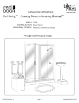
SERIES: 2000
CONFIGURATION: Door-Panel
MOUNTING PACKAGE: No header, glass-to-glass hinges,
u-channel on panel(s) and or return(s)
bottoms, wall clamps on panel(s) and or
return(s) wall sides, support bars from
walls to panels-returns
Redi Swing
TM
...Opening Doors to Stunning Showers!
TM
INSTALLATION INSTRUCTIONS
tile
redi
®
redi
DOOR
®
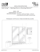
FRAMELESS INLINE DOOR
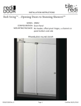
SERIES: 2000
CONFIGURATION: Door-Panel
MOUNTING PACKAGE: No header, glass-to-glass hinges,
u-channel on panel(s) and or return(s)
bottoms, wall clamps on panel(s) and or
return(s) wall sides, support bars from
walls to panels-returns
Redi Swing
TM
...Opening Doors to Stunning Showers!
TM
INSTALLATION INSTRUCTIONS
tile
redi
®
redi
DOOR
®
FRAMELESS INLINE DOOR
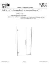
SERIES:
CONFIGURATION:
MOUNTING PACKAGE:
1200
Door-Panel
Frameless, connuous hinges, u-channel on
panel(s)/return(s) boom and wall sides
Redi Swing

RDQCI5029 Rev. 0 Page 2 Cered 06/01/2016
Installation Notes:
Proper blocking is required for every Heavy Glass unit prior to installation. At minimum 2x4
blocking is required at the location of any structural member of the unit including, but not lim-
ited to: hinges, clamps, and header brackets. All fasteners at these locations are required to
be installed into the blocking.
A minimum of 1 1/4” thread engagement is required of all fasteners into the blocking at these
locations. Depending on the application the customer maybe required to supply the proper
fasteners to ensure adequate engagement.
U-Channel maybe installed using wall plugs where no backing is found.
Use caution to not pierce plumbing or electric lines while installing door hardware.
Cover the drain with tape prior to installation to prevent loss of small parts.
Unpack your unit carefully and inspect for freight damage. Lay out and identify all parts using
the instruction sheet as a reference. Before discarding the carton, check to see that no small
hardware parts have fallen to the bottom of the box. If any parts are damaged or missing, refer
to the description noted in the instructions when contacting your dealer for replacements.
Maintenance:
Tools:
To install your New Shower Enclosure, you may need the following:
Pencil
Low Tack Tape
Tape Measure
4’ & 6’ Levels
#2 Phillips Screwdriver
Hack Saw
Caulk Gun
Clear Silicone Caulk
Suction Cups
Drill
1/8” & 3/16” Drill Bit
Center Punch
Files
This unit is best installed by two people.
Handle the glass panels carefully and protect the edges. Safety tempered glass is very re-
sistant to breakage, but the sharp corners of the panels can damage tile and flooring surfaces.
The glass can break if unequal pressure is applied during installation.
Please wear safety glasses whenever drilling or cutting. When drilling holes in ceramic tile or
marble, use a center punch and hammer to carefully break the glazed surface to prevent skid-
ding when drilling.
NOTE: Tempered glass cannot be cut.
Safety Notes:
Caring for Redi Clear™ Treated Glass
In order to maintain your ten year warranty, please follow these care instructions:
Once or twice a week, wipe down your shower door to remove body oils, soaps and shampoos from the surfaces.
The glass should be cleaned every few weeks using a damp microfiber cloth and a mild detergent or soap to
remove any soap scum and grime from the glass. Do not use paper towels or any abrasive tool to clean the
surface. The sealed surface is warranted with regular maintenance and without the use of any harsh chemicals or
detergents.
Caring for Non-Treated Glass
After each use, rinse with water and wipe down your enclosure with a soft cloth/towel or squeegee to maintain that
like-new look. The glass should be regularly cleaned using a damp microfiber cloth and a mild detergent or cleaner
to remove any soap scum and grime from the glass. We recommend Lysol Bathroom Cleaner as safe for shower
doors, but please test any commercial cleaning solutions on an inconspicuous area before applying to the entire
enclosure. Be sure to rinse all surfaces completely and wipe dry. Never use any abrasive material or harsh
chemicals to clean surfaces and do not allow cleaners to soak on surfaces.

RDQCI5029 Rev. 0 Page 3 Cered 06/01/2016
ITEM DESCRIPTION QT Y.
A CURB (W/ WEEP SLOTS) 1
B WALL JAMBS 2
C PLASTIC WALL ANCHORS 6
D #8 X 1-1/2” TRUSS HEAD SCREWS 6
E PLASTIC SETTING BLOCKS 2
F FIXED GLASS PANEL 1
G 180° POST 1
H HEADER 1
I MAGNETIC LATCH 1
K #8 X 1/4” TRUSS HEAD SCREWS 14
L HINGE JAMB
M STRIKE JAMB ASSY (W/MAGNET) 1
N SNAP-IN FILLERS 2
P DOOR PANEL 1
Q PLASTIC DOOR DEFLECTOR 1
HH VERTICAL GLAZING VINYL
JJ HORIZONTAL GLAZING VINYL
AA & BB INTERIOR & EXTERIOR HANDLE 1 EACH
CC METAL WASHERS 4
DD LARGE CLEAR DISCS 4
EE SMALL CLEAR DISCS 4
FF GLASS HOLE SLEEVES 2
GG STUD SCREWS 2
PARTS LIST

RDQCI5029 Rev. 0 Page 4 Cered 06/01/2016
EXPLODED VIEW

RDQCI5029 Rev. 0 Page 5 Cered 06/01/2016
CAUTION: For safety, the door must always open
outward.
1
SWING-LEFT
ALSO
CORRECT
SWING-RIGHT
Measure the wall-to-wall opening at the shower
sill and cut the curb [A] (with weep slots) to fit the full
width of the opening. If necessary, use a file to round
the lower corners of the curb to fit the shower sill
properly.
Using a 3/16” drill bit, drill the interior face of the curb
on both ends as shown. These holes may be pre-drilled
from the factory.
Position the curb in the middle of the sill with the weep
slots to the interior and mark its position with a pencil
line along the interior and exterior base.
2
MEASURE
SHOWER
SILL
CURB
3/8”
1/4”
3/16” DIA
ROIRETNI
Place the two wall jambs [B] into the ends of the
curb [A]. Masking tape may be used to hold the curb in
place during this operation. Plumb the jambs and mark
the hole locations on the wall. Remove all parts and
drill the walls for hardware.
For tile or marble walls, drill six 3/16” diameter holes
and insert the plastic wall anchors [C]. Attachments to
fiberglass or acrylic units can be made in two ways. If
reinforcement is built into the wall of the unit, drill six
1/8” holes to install mounting screws directly into the
reinforcement. If walls are not reinforced, drill six
3/16” holes and install plastic wall anchors or toggle
bolts (toggle bolts not supplied).
3
WALL
JAMB
CURB
WEEP SLOT
The frameless continuous hinge shower enclosure
is completely reversible and may be installed swing-left
or swing-right. The door may hinge from the wall or from
the center-post. For maximum waterproofing, the hinge
jamb should always be opposite the shower head.
Using the illustration, determine the correct
position for the door in your particular installation.
This instruction sheet depicts a hinge-right installation.
RDQCI5029 Rev 0 Page 4 Certified 06/21/2016

RDQCI5029 Rev. 0 Page 6 Cered 06/01/2016
Wipe the shower walls and sill, the curb [A] and
the wall jambs [B
] with a clean, dry cloth to remove
any dust or debris. Apply a 1/4” bead of caulk along the
inside of both of the pencil lines marked in Step #2
.
Carefully replace the curb in the exact position marked.
Caulk th
e inside of the curb ends where they meet
the wall.
Replace both wall jambs and attach to the
walls with six #8 x 1 1/2” truss head screws [D].
4
#8 x 1/2”
SCREW
WALL
JAMB
CURB
CAULK
WEEP SLOT
TO INTERIOR
Place two setting blocks [E] into the curb [A] to
support the fixed glass panel [F]. Position the b
locks 3”
from each corner of the glass panel. Set the glass panel
into place on the setting blocks and approximately 1/2”
into the wall jamb [B
]. A strip of masking tape 1/2”
from each vertical edge of the glass will aid alignment.
NOTE: Obscure or etche
d glass panels should be
installed with the rough or patterned surface of the
glass to the exterior of the unit.
Press the 180° post [G
] into the curb and position to
overlap the glass panel by 1/2”. Use masking tape to
hold the post in position temporarily.
NOTE: To facilitate out-of-
plumb walls, the 1/2” glass
bite may be varied from 1/4” to ¾”.
5
WALL
JAMB
1/2”
GLASS
PANEL
1/2”
180
POST
GLASS
PANEL
CURB
SETTING
BLOCK
Measure the wall-to-wall opening at the top of
the wall jambs [B] and cut the header [H
] to fit the
exact opening. Using a 3/16” drill bit, drill the interior
face of the header on both ends as shown. These holes
may be pre-drilled from the factory.
6
ROIRETNI
MEASURE AT TOP
OF WALL JAMB
”8/3
1/4”
HEADER
.AID ”61/3
L E NA P S S A L G
RDQCI5029 Rev 0 Page 5 Certified 06/21/2016

RDQCI5029 Rev. 0 Page 7 Cered 06/01/2016
Press the header [H] over the wall jambs [B] and
the 180° post [G]. Plumb the post, moving it laterally
as required to maintain proper coverage on the fixed
glass panel [F]. The minimum horizontal dimension for
the door opening is the door panel width (see
illustration in Step #8) plus 1/2”, maximum if the door
panel width plus 1 ¾”. Using the holes in the ends of
the header and curb as a guide, drill four 1/8” holes into
the wall jambs. Drill two 1/8” holes thru the header and
curb into the 180° post as shown, then enlarge the two
outer holes with a 3/16” drill for clearance on the self-
tapping screws. Secure the header and curb to the wall
jambs and 180° post with six #8 x 1/4” truss head
screws [K].
CAUTION: Slide the glass panel away from the wall
jamb before drilling to prevent damage or breakage.
7
Orient the door to the opening (either hinge right
Or hinge left). Place the door in the opening with the
door hinge over the wall jamb or post. Carefully hold the
door in the opening (in the open position) and don’t let go
of the door. Place the top filler to the under side of the
header WITH THE RAISED LIP TO THE EXTERIOR
and snap it into place.
Still holding the door in the opening move down to the
lower filler and snap it into place, being sure that the
raised lip of the filler is to the exterior.
8
EXTERIOR
FILLERS
1“
8/3 ” ”4/3 -
HINGE
JAMB
DOOR
PANEL
FILLER
CURB
WALL
JAMB
#8 x 1/4”
SCREWS
Pull the bottom end of the hinge jamb [L] tight
to the curb filler [N] and plumb the jamb. Drill two
1/8” holes thru the hinge jamb and into the wall jamb
[B] 3/8” to ¾” from the wall and approximately 1/4”
from the ends of the jamb. Drill a third hole centered
between the first two, then enlarge the three outer holes
with a 3/16” drill for clearance on the self-tapping
screws. Attach the pivot jamb permanently with three
#8 x 1/4” truss head screws [K].
Slide the header filler [N] tight against the hinge jamb.
Push the strike jamb [M] tight against the fillers top
and bottom. With the hinge jamb plumb and both fillers
tight between the two door jambs, the strike jamb also
will be plumb and parallel to the hinge jamb. Attach the
strike jamb to the 180° post [G] in the same manner as
the hinge jamb.
9
1/4” - 5/8”
(FROM CENTER
OF POST)
POST
DOOR
PANEL
HINGE
JAMB
WALL
JAMB
1/4”
1/4”
8/3 ” ”4/3 -
(6) #8 x 1/4”
SCREWS
STRIKE
JAMB
GNINEPO
3/8”
(6) #8 X 1/4”
SCREWS
1/4”
1/4”
RDQCI5029 Rev 0 Page 6 Certified 06/21/2016

RDQCI5029 Rev. 0 Page 8 Cered 06/01/2016
Slide the door [I] magnet onto the strike edge
of the door panel. Close the door and slide the handle
up or down until the two magnetic strips are aligned.
Use a pencil or masking tape the mark the location of
the magnet on the door.
Slip the vinyl material onto the door between the marks
and carefully drive the door magnet on the door panel.
Trim excess vinyl material off with a utility knife.
Close the door and check for proper operation of the
magnetic catch.
NOTE: Never hit the door magnet with a metal
hammer.
10
INTERIOR
VINYL
STRIKE
JAMB
MAGNETIC
LATCH
MAGNET
1/8”
SEE SUPPLEMENT INSTRUCTION SHEET
FOR INSTALLATION OF EITHER THE “C” PULL
HANDLE OR “C” TOWEL BAR COMBO.
11
NOTE: The deflector [Q] is notched on both
ends. To install deflector, determine if the door is hinge
right or hinge left.
12
RDQCI5029 Rev 0 Page 7 Certified 06/21/2016

RDQCI5029 Rev. 0 Page 9 Cered 06/01/2016
Align the deflector [Q] to the bottom of the
door with the hinge side notch over lapping the hinge,
then mark the strike side even with the door edge cut
deflector at that point.
13
INTERIOR
Place the deflector onto the bottom of the door
and from inside the shower, close the door and mark
the deflector at the edge of the strike jamb. Open the
door and remove the deflector. Notch the inside portion
of the deflector so the door will close to the strike jamb.
Replace the deflector back on the door; close the door
to check for clearance.
14
EXTERIOR
Inspect the pieces of black glazing vinyl, and
note the two different profiles. The smaller shape [HH]
is installed vertically and the larger shape [JJ] is
installed horizontally. For structural strength and
maximum water resistance, these vinyls are designed to
fit tightly between the glass and framing. To speed
installation, use glass cleaner for lubrication and a
small block of wood to press the vinyl into place.
15
FIXED GLASS PANEL
VERTICAL
HORIZONTAL
1/4” GLASS
REQUIRES :
3/16” GLASS
REQUIRES :
V-219
V-220
V-226
V-225
NOTCH
NOTCH
STANDARD SIZES
SHIPPED WITH
4 PIECE VINYLS
(TEAR APART)
RDQCI5029 Rev 0 Page 8 Certified 06/21/2016

RDQCI5029 Rev. 0 Page 10 Cered 06/01/2016
Cut four pieces of the smaller vinyl [HH] 1”
longer than the vertical opening (to prevent gapping
from shrinkage) and trim the ends on a 45° angle.
Using the masking tape guides, center the glass panel
[F] in the frame. Cut four short (1” – 2”) pieces of the
small vinyl and press into the jamb and post on each
side to hold the glass temporarily.
Take one of the long pieces of vinyl, and starting on the
outside exterior jamb, press each end into the frame and
work toward the middle. Be careful not to stretch the
vinyl. Install the other three pieces in a similar fashion.
16
GLAZING
VINYL
WALL
JAMB
GLASS
PANEL
180
POST
45
ANGLE
Cut four pieces of the larger vinyl [JJ] 1/2”
longer than the horizontal opening and trim the ends on
a 45° angle. Install the top exterior vinyl starting at
both ends and working toward the middle. Be careful
not to stretch the vinyl.
Install the top interior vinyl and the two bottom vinyls
in the same way.
17
G L S S A P L E NA
HEADER
GLAZING
VINYL
CURB
GLASS
PANEL
SETTING
BLOCK
Carefully caulk the interior jamb-to-wall and
curb-to-base joints. For appearance, you may wish to
caulk the exterior joints as well. We recommend you
wait twenty-four hours before the first shower to allow
the caulking to cure properly.
18
KLUAC
Note: Do not caulk over weep holes
G L S S A P L E NA
RDQCI5029 Rev 0 Page 9 Certified 06/21/2016

RDQCI5029 Rev. 0 Page 11 Cered 06/01/2016
INSTALLATION INSTRUCTIONS
–
ACCESSORIES
Combination Door Pull and Towel Bar Installation Instructions
There are eleven hardware components for Combination Door Pull and Towel Bar mounting: Six 1
-
1/4” style washers; one towel bar; one pull; two end caps with threaded studs; one stud head screw. In
addition to these hardware parts, there are six clear gaskets th
at act as a buffer between the hardware
and the glass.
STEP 1 Take the stud head screw and sleeve a 1-
1/4” style washer on it. Now take both end caps with a
stud protruding and sleeve a 1-1/4” style washer on
them. Sleeve a clear gasket on each of the screws.
STEP 2 The towel bar will be mounted first. Take
the stud head screw with the washer and gasket attached,
and from the inside of the enclosure push the threaded
portion through the top hole in the glass on the strike
side of the door. Place a clear gasket, then a 1-1/4” style
washer over the stud head screw on the outside of the
glass door. Now thread the stud head screw into the
towel bar and tighten. On the other end of the towel bar
(on the hinge side), push one of the end caps with the
stud protruding through the hole. Now place a clear
gasket, then a 1-1/4” style washer over the threaded stud
on the outside of the glass door. Thread the end cap into
the towel bar and tighten by hand. Tighten both
components down, the stud head screw with a
screwdriver, and the end cap by hand.
STEP 3 The towel bar is now complete and it is time to mount the pull portion. From outside
the enclosure, push the end cap with the stud protruding through the bottom hole of the door. First
place a clear gasket, then a 1
-
1/4” style washer over the threaded stud on the inside of the glass door.
Now thread the stud into the small threaded opening of the pull. Do not tighten this end of the pull
down at this time. Place the end of the pull with the large hole and the set screw over the stud head.
Now tighten the end cap by hand as tight as possible. Use the Allen wrench provided to tighten the set
screw on the pull to the stud head screw.
P
J
T
L
M
N
O
RDQCI5029 Rev 0 Page 10 Certified 06/21/2016

RDQCI5029 Rev. 0 Page 12 Cered 06/01/2016
There are six hardware components for back
-to-back mounting: two pulls and four 1-
1/4” diameter
style washers. In addition to these hardware parts, there are four clear gaskets and two stud head
screws. A decision must be made at this time as to the location of the half of the pull that contains the
set screws. Most put the set screws to the outside of the enclosure, so they are not exposed to direct
water contact. These instructions will address this application.
STEP1
Take the two stud head mounting screws and sleeve on 1-
1/4” style washer on each
screw. Next, sleeve one of the clear gaskets onto the screw. From the outside of the enclosure, push
the thread of the screw through the hole in the glass. On the inside of the enclosure, sleeve a clear
gasket onto the threads of the screw. Place the 1
-1/4” style washer over the threads and onto the glass.
STEP 2 Take the pull that has the smaller threaded holes in each end and begin to thread the
screw into it. Line up the other end of the pull with the other screw and begin to thread it through as
well. Tighten both screws to “finger
-
tightness”, then tighten the stud head screws down permanently
with a screwdriver.
STEP 3
Place the remaining pull, with the large holes in each end as
well as a set screw, onto
the stud heads of the screws. Tighten the set screws with the Allen wrench provided.
J
K
L
M
N
O
P
Back-To-Back Door Pull or Towel Bar Mounting Instructions
RDQCI5029 Rev 0 Page 11 Certified 06/21/2016
/