Page is loading ...

Semi-
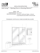
Frameless
Continuous
Hinge
Shower
Door
INFN00A
the INFINITY SINGLE SWING
BECAUSE THE SHOWER IS EVERYTHING
www.BascoShowerDoor.com | 800.45.BASCO
QCI5028

INSTALLATION NOTES: Unpack your unit carefully and inspect for freight damage. Lay out and
identify all parts using the instruction sheet as a reference. Before discarding the carton, check to see
that no small hardware parts have fallen to the bottom of the box. If any parts are damaged or missing,
refer to the descriptions noted in the instructions when contacting your dealer for replacements.
Handle the glass panel(s) carefully and protect the edges.
Please wear safety glasses whenever drilling or cutting. When drilling holes in ceramic tile or marble,
use a center punch and hammer to carefully break the surface glaze so the drill bit can start without
skidding.
To install your shower door, you will need the following: tape measure, level(s), #2 Phillips
screwdriver, drill, 1/8” & 3/16” High Speed Steel drill bits, hacksaw, pencil, sharp knife or razor blade
and caulking (clear, mildew resistant silicone recommended). Optional tools include a miter box for
cutting metal parts, file, center punch and masking tape. An additional 3/16” Masonry drill bit is
recommended for tiled applications.
The door is best installed with two people.
NOTE: Tempered glass cannot be cut.
Although safety tempered glass is very resistant to breakage, the glass can still break if unequal
pressure is placed on it during installation. Use caution! In addition, the sharp corners of the
panel can damage tile and floor surfaces, so its best to handle the glass panels carefully and
protect the edges.
MAINTENANCE: Two primary materials are used to manufacture your new shower enclosure:
tempered glass and anodized aluminum. To assure a long lasting finish on the enclosure,
wipe it down with a towel after each use. Never use a scouring pad/agent to clean the aluminum.
For occasional, more concentrated cleaning efforts, we recommend using LYSOL™ Non-Abrasive
Bathroom Cleaner works extremely well. Be sure that any over spray falling on the aluminum frame
is rinsed thoroughly and dried. Many over-the-counter cleaners, if applied to aluminum and left on,
will harm the finish and cause permanent damage, even though their directions indicate safe use on
shower doors.
For glass treated with AquaGlide™, read the following instructions:
After each use of your shower, use a small plastic bowl, pitcher or a hand held shower head to spray
the shower doors with clean cold water. Pour or spray the cold water along the top edge of the glass.
The majority of the shower’s soapy residual water will drain off. Use a small hand towel to pat dry
the remaining droplets or use a squegee to clear the droplets.
Once a month, use a nylon sponge to go over the wet glass, rubbing in a circular motion. You should
feel “sticky” places going back to slick again. Then pour water along the top edge of the glass, as you
do after each shower use.
QCI5028 Rev 1 Page 2 Certified 09/19/2018

1/4” FRAMELESS DOOR PARTS
A. Shower Curb (1) F. #8 x 1 1/2” Truss Head Screws (6)
B. Glazed Door Panel Assembly (1) G. #6 x 3/8” Tech Screws (self-tapping) (6)
C. Clear Bottom Sweep (1) H. Strike Jamb w/ Magnet & Vinyl (1)
D. Wall Jambs (2) I. Latch w/ Strike Plate & Vinyl (1)
E. Plastic Wall Anchors (6) J - P. Handle Assembly (1)
(see supplement Pg. 9 or Pg.10)
QCI5028 Rev 1 Page 3 Certified 09/19/2018

1 The 1/4” frameless door is completely
reversible and may be installed hinge-right or hinge-left.
Refer to the illustration to determine the best hinge
position for your installation.
For maximum waterproofing, the hinge jamb should
always be opposite the shower head. The following
instructions depict a hinge-left installation.
CAUTION: For saftey purposes, the door must
always open outward!
NOTE: To allow for this unit to be reversible, the
hinge jamb extends 9/16” beyond both ends of the
door panel. Once the hinge-side of the door has been
determined (see above), the 9/16” extension can
be cut off from the TOP only for a more streamlined
finished look. (If this is done, don’t forget to cut
9/16” off the top of the longer wall jamb as well).
TIP: Temporarily cover the drain on the inside
of the shower with some tape or a large peice of
cardboard to prevent small screws, drill bits, etc
from disappearing.
2 NOTE: The unit may be installed without
using the provided sloped curb [A]. Its’ use is definitely
recommended for positive water control when installed
on shower sills with little or no slope.
If it is not used, skip this step.
Measure the finished wall-to-wall opening at the
shower sill and cut the curb to that exact length.
File the ends of the curb as necessary to fit the
corners of the opening. Place the curb on the
shower sill, with the RAISED side to the exterior
of the enclosure. Make sure the curb is centered on
the sill and lightly mark its’ position, both inside
and out, on the sill with a pencil.
Remove the curb from the sill and run two beads
of silicone inside of the pencil marks on the shower
sill. Place the curb back in the exact same position as
marked. Use a few pieces of tape, placed over the curb
from inside to outside, to hold the curb in place during
the remainder of the installation.
HINGE LEFT HINGE RIGHT
QCI5028 Rev 1 Page 4 Certified 09/19/2018

3 NOTE: Wall jambs for this unit are different
lengths. Be sure to use the longer wall jamb on the
designated hinge side.
Place the longer wall jamb [D] against the hinge side
wall with the bottom end 3/16” for the start of the raised
lip on the curb (see illustration). Plumb the wall jamb
with a level and mark the three hole locations on the wall.
Repeat using the shorter wall jamb on the strike side wall.
Set the wall jambs to the side and drill the holes
for the mounting hardware.
Tile or marble walls:
Drill 3/16” diameter holes into the walls and insert
the plastic wall anchors [E].
Fiberglass or acrylic units can be done two different ways:
If the walls are not reinforced, drill 3/16” diameter
holes and insert the the plastic wall anchors. (Toggle
bolts may be used instead but they are not provided).
If the walls are reinforced, only drill 1/8” diameter holes.
Attach the correct wall jamb to each wall using the #8 x 1 1/2”
truss head screw [F].
QCI5028 Rev 1 Page 5 Certified 09/19/2018
DW
EXTERIOR
OW
i. Measure the Door Width (DW) and write it down.
ii. Measure the wall-to-wall distances at the top and bottom
of the wall jambs and find the smaller dimension. If both
dimensions are the same then use the bottom as the smaller.
iii. Slide the strike jamb [F] over the mounted wall jamb
[B] with the magnet facing the exterior of the shower and make
sure it is plumb.
iv. Measure the Opening Width (OW) from the strike jamb
[F] to the opposite wall jamb [B] at the point of the smaller
dimension found earlier.
v. If OW is greater than (DW + 3/8”) AND less than (DW
+ 7/8”) then the mark the location of the Strike Jamb with a
pencil. Skip to Step 5.
a. ___________ (DW) + .375” > ___________ (OW)
AND
b. ___________ (DW) + .875” < ___________ (OW)
vi. If not between measurements, slide the strike jamb in or
out until it satisfies the above. Be sure to keep it plumb.
i
ii
iv
iii
B
F
B

5 Inside the shower enclosure, using the pencil
marks on the wall jambs from the previous step, drill
two 1/8” holes through the strike jamb [H] and into
the wall jamb 3/8” to 3/4” from the wall and
approximately 1” down from the top and up from
the bottom of the strike jamb. Drill a third hole
centered between the first two.
Remove the strike jamb and enlarge the three holes in
the strike jamb only to allow clearance for the screws.
Attach the strike jamb permanently with three #6 x 3/8”
pan head screws [G].
6 Slide the hinge jamb of the door panel
assembly over the mounted wall jamb so the
door will open outward. Adjust the door panel
assembly so there is a 1/4” clearance between
the strike jamb and the strike edge of the glass
door with it being in the closed position.
Mark the location of the hinge jamb on the wall
jamb with a pencil.
7 Inside the shower enclosure, using the pencil
marks on the wall jambs from the previous step, drill
two 1/8” holes through the hinge jamb of the door
panel assembly and into the wall jamb 3/8” to 3/4”
from the wall and approximately 1” down from the
top and up from the bottom of the hinge jamb.
Drill a third hole centered between the first two.
Remove the door panel assembly and enlarge the three
holes in the hinge jamb only to allow clearance for the
screws.
Attach the door panel assembly permanently with three
#6 x 3/8” pan head screws.
QCI5028 Rev 1 Page 6 Certified 09/19/2018

STRIKE
PLATE
STRIKE PLATE
VINYL
LATCH
LATCH
8 Slide the door latch [I] onto the strike side of
the door panel. Close the door and slide the latch up
and down until the magnet and strike plate are aligned.
Use a pencil and/or masking tape to mark the location
of the latch on the door.
Fold the vinyl material [over the strike edge of the
door and carefully drive the latch onto the door
panel using a rubber or plastic mallet.
Close the door and check for proper operation of the
latch and magnet. (If adjustment is needed, use a rubber
or plastic mallet and a wood block and lightly tap into
place). Trim the excess vinyl off with a utility knife.
NOTE: NEVER hit the door latch with a
metal hammer!!
9 See supplement instruction sheets for installation
of either the double-sided “C” pull handle or the
“C” pull handle/towel bar combo.
10 NOTE: The clear bottom sweep [C] is
notched on both ends. For installation, determine
if the door is hinge right or hinge left.
DOOR
GLASS
QCI5028 Rev 0 Page 7 Certified 06/21/2016

11 Align the clear bottom sweep to the
bottom of the door with the deflector lip on the
inside of the shower door. Mark the strike side
of the bottom sweep even with the strike edge
of the door.
Cut the sweep leaving the notched part under
the metal rail.
12 Place the sweep onto the bottom of the door.
Stand inside the shower, close the door and mark the
deflector part of the sweep at the inside edge of the
strike jamb.
Open the door and remove the sweep. Notch the
inside portion of the sweep so the door glass will
close tightly to the strike jamb vinyl.
Place the sweep back on the door and check for
clearance.
INTERIOR
ENOCILIS
13 Carefully silicone the seam between the walls
and the wall jambs as well as the curb and threshold
on the inside of the shower.
NOTE: Silicone on the exterior seam is optional.
DO NOT USE the shower until the silicone is
completely cured. Check the tube of silicone
for the manufacturer recommended cure time.
(typically 24 - 48 hours)
QCI5028 Rev 1 Page 8 Certified 09/19/2018

“C” Pull Handle / Towel Bar Combination
Installation Instructions
There are eleven hardware components for the combination pull/towel bar mounting: Six 1 1/4” metal washers,
one towel bar, one “C” pull, two end caps with threaded studs, one stud head screw. In addition to these
hardware parts, there are six clear gaskets that act as a a buffer between the hardware and the glass.
STEP 1 Take the stud head screw and sleeve a 1 1/4” washer on it. Now take both end caps with a
threaded stud protruding and sleeve a 1 1/4” washer on them. Sleeve a clear gasket on each of the screws.
STEP 2 The towel bar will be mounted first. Take the stud head screw with the washer and gasket
attached and, from the inside of the enclosure, push the threaded portion through the top hole in the glass
on the strike side of the door. Place a clear gasket and then a 1 1/4” washer over the stud head screw on
the outside of the glass door. Next, thread the stud head screw into the towel bar and tighten. On the other
end of the towel bar, on the hinge side, push one of the end caps with the protruding threaded stud through
the hole in the glass. Now place a clear disc and then a 1 1/4” washer over the threaded stud on the outside
of the glass door. Thread the end cap into the towel bar and tighten by hand. Tighten both components, the
stud head screw with a screw driver and the end cap using a small allen wrench in the hole in the side of
the end cap.
STEP 3 Place a plastic disc over the end cap and, from the outside of the enclosure, push the end cap
with the protruding threaded stud through the bottom hole in the door glass. Next, thread the stud into the
small threaded opening of the pull handle. Do not fully tighten yet. Place the end of the pull handle with the
large hole and the set screw over the stud head. Now tighten the end cap as tight as possible using a small
allen wrench in the hole in the side of the end cap. Use the larger allen wrench to tighten the set screw, in
the under side of the pull handle, to the stud head screw.
J Interior pull handle (1)
K Towel bar (1)
L Metal washers (6)
M Large clear discs (6)
N Small clear discs (6)
O Glass hole sleeve (3)
P Stud screw (1)
Q Threaded end cap (2)
J
P
Q
Q
N
O
K
L
M
QCI5028 Rev 1 Page 9 Certified 09/19/2018

STEP 1 Using the provided Allen wrench, loosen the two set screws located on the under side of one
of the handles near the washers. Seperate the handle from the stud screws and collars.
STEP 2 Using a Phillips-head screwdriver, loosen and carefully remove the stud screws, collars, clear
discs and glass hole sleeve from the other handle.
STEP 3 Remove the interior metal washer, large and small clear disc from the stud screw, leaving the
exterior washer, clear discs and hole sleeve on the stud screw with the collar. Careful not to
lose any of the pieces.
STEP 4 From the outside of the door, push the stud screw with collar through the hole in the glass. Be
sure the hole sleeve is between the threads of the screw and the glass.
STEP 5 From the inside of the door, slide the large clear disc onto the screw. Next, slide the metal
washer then the small clear disc over the screw. Finally, thread the screw into the interior
handle (the one with the smaller threaded holes). Don’t tighten. Install the other stud screw
with collar and washers through the other handle hole in the glass. After both stud screws are
threaded into the interior handle, hold in position and tighten the stud screws with a Phillips-
head screwdriver pulling the interior handle tight to the glass.
STEP 6 From the outside of the door, position the exterior handle over the collars of both stud screws
and tighten the set screws with the Allen wrench.
J Interior handle (1)
K Exterior handle (1)
L Metal washers (4)
M Large clear discs (4)
N Small clear discs (4)
O Hole sleeve (2)
P Stud screw w/ collar (2)
J
K
L
M
N
O
P
L
M
N
Back-to-Back Door Pull Installation Instructions
QCI5028 Rev 1 Page 10 Certified 09/19/2018

-
CONTINUOUS HINGE ASSEMBLY PROCEDURE
Measure 4" from the notch and
cut off the Spacer Sleeve
Step - 5
Page B
Flush
Step - 1
Step - 2
Step - 3
Step - 4
5/17/2017
Continuous Hinge KD Instructions
Step - 6
After Completing these steps, install the unit as described
begining on Page 2 of the instructions

Connuous Hinge KD Instrucons Page A 5/17/2017
ITEM # PART # DESCRIPTION QTY.
1 SC4643 MOUNT BUSHING 2
2 SC4642 HINGE BUSHING 2
3 SC4644 SPACER SLEEVE 1
4 SC5018* #8 SCREW 2
*Please note: Framed units use SCR05 and has
slightly dierent extrusions, but the hinge assembly
procedure is idencal.
/