Page is loading ...

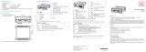
IMS5400-DS
IMS5600-DS
IMS5400-TH
Quick Manual
interferoMETER

MICRO-EPSILON
MESSTECHNIK
GmbH & Co. KG
Koenigbacher Str. 15
94496 Ortenburg / Germany
Tel. +49 (0) 8542 / 168-0
Fax +49 (0) 8542 / 168-90
e-mail [email protected]
www.micro-epsilon.com
You can find further information about the measurement
system in the operating instructions. They are available at:
Contents
General .......................................................................... 3
Symbols used ....................................................................3
Warnings ............................................................................3
Intended Use ......................................................................4
Proper Environment ...........................................................4
Glossary .............................................................................5
Laser Safety ................................................................... 5
Operating Modes ........................................................... 6
Setup, Connection Options .......................................... 6
Sensor Cable .....................................................................7
Mounting, Mounting Adapter ............................................. 7
Pluggable Screw Terminals ...............................................8
LEDs Controller ............................................................. 9
Button Multifunction .........................................................10
Initial Operation ........................................................... 11
Select a Sensor ................................................................ 11
Start of Measuring Range, Working Distance .................11
Positioning the Target, Distance Measurement ............... 12
Positioning the Target, Thickness Measurement.............13
Material Selection .............................................................13
Measurement Configuration ............................................14
FFT Signal Check ............................................................15
Signal Quality ..................................................................15
Distance and Thickness Measurement with Web Page
Display ......................................................................... 16
Data Output, Interface Selection ................................ 18
Ethernet ....................................................................... 18
Set IP Address ............................................................. 19
Service, Repair ............................................................ 19
Liability for Material Defects ...................................... 19
www.micro-epsilon.com/download/manuals/
man--interferoMETER-5x00--en.pdf

Page 3
General
IMS5x00
General
Symbols used
The following symbols are used in this document:
CAUTION
Indicates a hazardous situation which, if not avoided, may result in minor or moderate injury.
NOTICE
Indicates a situation that may result in property damage if not avoided.
Indicates a user action.
i
Indicates a tip for users.
Measure
Indicates hardware or a software button/menu.
Warnings
CAUTION
Connect the power supply and the display/output device according to the safety regulations for
electrical equipment.
> Risk of injury, damage to or destruction of the controller
NOTICE
The supply voltage must not exceed the specified limits.
> Damage to or destruction of the controller
Avoid shocks and impacts to the sensor and the controller.
> Damage to or destruction of the components
Never kink optical fibers or bend them in thight radii.
> Damage to or destruction of the optical fibers; failure of measurement device
Protect the ends of the optical fibers against contamination
> Failure of the measuring device
Protect the cable against damage.
> Failure of the measuring device

Page 4
General
IMS5x00
Intended Use
- The interferoMETER measuring system is designed for use in an industrial environments and domestic areas.
It is used for
measuring displacement, distance, profile, thickness and surface inspection
monitoring quality and checking dimensions.
- The measuring system must only be operated within the limits specified in the technical data.
- The measuring system must be used in such a way that no persons are endangered or machines and other
material goods are damaged in the event of malfunction or total failure of the controller.
- Take additional precautions for safety and damage prevention in case of safety-related applications.
Proper Environment
- Protection class
sensor: IP40 (with connected sensor cable only)
controller: IP40
Lenses are excluded from protection class. Contamination of the lenses causes impairment or failure of the function.
- Temperature range
operation
• sensor: +5 ... +70 °C (+41 ... +158 °F)
• controller: +15 ... +35 °C (+59 ... +95 °F)
storage: -20 ... +70 °C (-4 ... +158 °F)
- Humidity: 5 - 95 % (non-condensing)
- Ambient pressure: Atmospheric pressure
- EMC: According to EN 61000-6-3 / EN 61326-1 (Class B) and EN 61 000-6-2 / EN 61326-1

Page 5
Laser Safety
IMS5x00
Glossary
MR = Measuring range
SMR = Start of measuring range
MMR = Mid of measuring range (=SMR + 0.5MR)
SMRDistance sensor
Thickness sensor
Working distance
Operating range
MR
Measurement object
You can find further information about the sensors in the
operating instructions, chapter Technical Data.
Laser Safety
The interferoMETER measuring system works with a
pilot laser of a wavelength of 635 nm (visible / red)
offering max. power of < 0.01 mW and a measuring
laser of a wavelength of 840 nm with a max. power of
< 0.2 mW.
The measuring system falls within laser class 1. The
accessible radiation is harmless under predictable con-
ditions.
For class 1 laser devices, impairment of color vision
and disturbances, e.g., from a glare effect, cannot be
excluded.
An LED signalizes by illumination that laser radiation
emits from the optical opening of the light source
(“Pilot on”).
Class 1 Laser Product
IEC 60825-1: 2014
P≤0.01 mW; =635 nm
COMPLIES WITH 21 CFR 1040.10 AND 1040.11
EXCEPT FOR CONFORMANCE WITH IEC 60825-1
ED. 3., AS DESCRIBED IN
LASER NOTICE NO. 56, DATED MAY 8, 2019.
Class 1 Laser Product
IEC 60825-1: 2014
P≤0.2 mW; =840 nm
COMPLIES WITH 21 CFR 1040.10 AND 1040.11
EXCEPT FOR CONFORMANCE WITH IEC 60825-1
ED. 3., AS DESCRIBED IN
LASER NOTICE NO. 56, DATED MAY 8, 2019.
LASER Klasse 1
nach DIN EN 60825-1: 2015-07
P≤0,01 mW; =635 nm
LASER Klasse 1
nach DIN EN 60825-1: 2015-07
P≤0,2 mW; =840 nm

Page 6
Operating Modes
IMS5x00
Operating Modes
The interferoMETER measuring system provides highly
accurate measurements of
- distances against visually dense materials with
light-diffusing or reflective surfaces
- thicknesses for transparent layer materials.
By selecting the sensor, the distance or thickness mea-
surement operating mode is selected.
Accordingly, the result of the measurement is a distance
or thickness value.
Distance
measurements
Thickness
measurements
Measuring range 2.1 mm
35 µm ... 1.4 mm
1
Measuring ranges for distance and thickness measure-
ments
The possible resolution here is in the nanometer range.
For a quick start, we recommend to use presets defined
for different target surfaces and applications, see operat-
ing instructions Chap. 6.6.
1) Measuring range with n=1.5; for air gap measure-
ment between two glass plates (n~1) the measuring
range is 0.05 ... 2.1 mm. The measurement object
must be within the working distance.
Setup, Connection Options
Connect the components together and mount the
sensors into the clamps.
Patch cable
Run
X1
X2
PS2020
230 VAC
PE
N L
Ethernet
EtherCAT
Controller
PC
PS 2020
2-Port
EtherCAT
Junction
Sensor
IF2001/USB IF2008/PCIE
SC2471-x/RS422/OE
SC2471-x/IF2008

Page 7
Setup, Connection Options
IMS5x00
Sensor Cable
Sensor and controller are connected through an
optical fiber.
- Do not shorten or extend the optical fiber.
- Do not pull or hold the sensor on the optical fiber.
Do not kink the optical
fiber.
Do not crush the opti-
cal fiber, do not fasten
it using cable ties.
Please do not grind the
optical fiber over sharp
corners.
Do not pull the optical
fiber.
Cleaning of the connectors requires the
corresponding know-how.
General Rules
As a matter of principle, avoid:
- any contamination of the connector, e.g., dust or finger
prints
- unnecessary mating cycles.
- any mechanical stress of the optical fiber (bending,
crushing, pulling, twisting, knotting etc.).
- tight curvature of the optical fiber because the glass fiber
is damaged in the process and this causes permanent
damage.
Never bend the cable more tightly than the permissible
bending radius.
R
Fixed: R = 30 mm or more
Flexible: R = 40 mm or more
Mounting, Mounting Adapter
The IMP-DS19 / -TH45 series sensors use an optical measur-
ing principle that allows for measurements in the nm range.
i
Ensure careful handling during installation and opera-
tion.
Mount the sensors with an outer clamp. Use the MA5400-
10 mounting adapter from the optional accessories.
This type of sensor installation ensures the highest level of
reliability because the sensor’s cylindrical cover is clamped
over a relatively large area.

Page 8
Setup, Connection Options
IMS5x00
Pluggable Screw Terminals
Pin Description Comments
U/I out
GND
Shield
Analog Out
U/I out
Voltage output
0 ... 5 V; 0 ... 10 V; R
i
appr. 50 Ohm
5.5 V / 10.9 V with error, outside measuring
range
Current output
4 ... 20 mA; R
L
≤ 500 Ohm
23.7 mA with error, outside measuring range
GND Ground analog output Galvanically connected with supply
+Sync/Trig
-Sync/Trig
Synchronization input/out-
put, trigger input
RS422 level (EIA422)
+ Sync/Trig
- Sync/Trig
Digital I/O
GND
Shield
TrigIn
GND
Error 1
GND
Shield
Error 2
GND
TrigIn Trigger input
TTL or HTL level
TTL: Low ≤ 0.8 V, High ≥ 2 V
HTL: Low ≤ 3 V, High ≥ 8 V
Error 1 / 2 Switch outputs
NPN, PNP or Push-Pull
I
max
= 100 mA, U
H max
= 30 V
GND Ground potentials
All GND conductors are interconnected with
one another and to operating voltage ground.
24 VDC Operating voltage ± 15 %, I
max
< 1 A
24 VDC
GND
Shield
Power
GND Operating voltage ground
GND is galvanically connected to GND of
switching outputs, synchronization, analog
and encoder input
Shield Shields to respective output/input, connector housing
The plug-in screw terminals are designed for a conductor cross-section of 0.14 mm² up to 1.5 mm².

Page 9
LEDs Controller
IMS5x00
LEDs Controller
Power on Green Operating voltage available
Status
Off No error
If EtherCAT is active, meaning of the LED is conform with the Ether-CAT guidelines.
Intensity
Red Signal in saturation
Yellow Signal too low
Green Signal ok
Range
Red No target object, or target object outside the measuring range
Yellow Target close to mid of measuring range
Green Target within measuring range
SLED
Red SLED of
Yellow SLED warms up
Green SLED ready for operation
Yellow flashing SLED current outside the optimal value range
1
Pilot
Red Pilot laser off
Green Pilot laser on
Green
Pilot laser is alternately turned on and off,
if no target object or outside the measuring range
1) When measuring outside the optimum current value of the SLED, the controller will measure, but the measurement
accuracy may not be as specified.
The LED’s Intensity and Range flashes with their current color during a synchronization error.

Page 10
LEDs Controller
IMS5x00
Button Multifunction
The Multifunction button of the controller has multiple functions. It enables, e.g., to operate the light source.
The button is factory-set to the Pilotlaser on/off feature.
Key function
1 / 2
Set / reset
master value
Starts or stops the master measurement of the selected signals
Pilot laser Turns on/off the pilot laser
SLED Turns the light source on/off for the sensor
Inactive Key has no function
There are two defined time intervals for pressing the button; each of these can be assigned a function. All time inter-
vals are indicated by the LEDs flashing/lighting up.
Pilot laser
SLED
Master value
Function 1
2 sec0 5 sec 10 sec 15 sec
Function 2
Key
lock
x min time
Factory
settings
Button press duration

Page 11
Initial Operation
IMS5x00
Initial Operation
i
Initializing starts after the voltage supply has been
switched on. The measuring system is ready for
use after approx. 10 seconds. To ensure precise
measurements, let the measuring system warm up
for approx. 60 minutes.
The controller is factory set to the static IP address
169.254.168.150. Use this address for a direct connec-
tion with a browser.
The start screen of the controller software is displayed in
the web browser now.
You can check the IP address of the controller, that are
connected to a PC / network, with the sensorTOOL.
exe program. This program is available online at https://
www.micro-epsilon.de/download/software/sensorTOOL.
exe.
Start the program sensorTOOL and click the button
.
Click the Open WebPage button to connect the
controller to your default browser.
Select a Sensor
Change to the Settings > Sensor menu.
Select a sensor from
the list.
Start of Measuring Range, Working Distance
A base distance (SMR) or working distance must be main-
tained for each sensor.
Distance sensor SMR
Thickness sensor
Working distance
Operating range
MR
Measurement
object

Page 12
Initial Operation
IMS5x00
Positioning the Target, Distance Measurement
The red-light pilot laser supports you in aligning the
sensor to the target during commissioning.
Turn on or off the pilot laser in the menu Settings >
System settings.
Position the target (measurement object) as much
as possible in the mid of the measuring range.
100 %
50
0
Sensor
SMR
SMR MMR EMR
Dis-
tance
Signal
Target
Measuring range (MR)
max. ±1 °
The LED Range on the controller front indicates the
position of the target in relation to the sensor.
Green
Pilot laser is turned on and
off alternately, if no target or
outside the measuring range
You can also position the sensor using the FFT sig-
nal
1
. The interferometric measuring principle provides
measurement values in front of and behind the actual
measuring range. An incorrect measuring range dis-
tance can be recognized by the running direction of the
peak in the FFT signal. Inverse direction of FFT signal, if
the target is outside measuring range.
Distance between sensor
and target becomes smaller
Distance between sensor
and target becomes greater
Using the FFT signal for sensor positioning
Red
No target or target outside the
measuring range
Yellow
Target close to mid of
measuring range
Green Target within measuring range
1) FFT = Fast Fourier Transformation, frequency signal

Page 13
Initial Operation
IMS5x00
Material Selection
To measure the thickness of a material, you must specify
the material of the target.
Change to Material selection, menu Settings >
Data recording.
Select the material based on the target used.
In the controller, you can store the group refractive index
of different materials which can be used for direct reflec-
tion measurements.
The materials database in delivery state can be restored
by loading the factory settings. The materials database
allows for up to 20 materials to be stored.
If the corresponding material is now specified for the
measurement, the refractive index is included in the cal-
culation and the sensor thus delivers the correct result.
Clicking on the button Edit material table expands/
reduces the materials database. For a new material, the
group refractive index is required.
1) The maximum thickness for a air gap is 2.1 mm. The
thickness for glass (n = 1.5) is 35 µm as a minimum
and 1.4 mm as a maximum.
Positioning the Target, Thickness Measurement
The red-light pilot laser supports you in aligning the
sensor to the target during commissioning.
Turn on or off the pilot laser in the menu Settings >
System settings.
Position the target (measurement object) as much
as possible in the mid of the operating range.
The peak positions remains stable in the FFT signal,
even though the measurement target moves. The peak
position depends on the target thickness.
Operating range
Working distance
Measuring range
thickness
1
Basics thickness measurement
The LED Range on the controller front indicates the
position of the target in relation to the sensor.
Green
Pilot laser is turned on and off
alternately, if no target or
outside the measuring range

Page 14
Initial Operation
IMS5x00
Measurement Configuration
Common measurement configurations (presets) for various target surfaces are stored on the controller and enable to
quickly start the respective measurement task. This allows you to quickly start with your individual measurement task.
In a preset the basic features like peak or material selection and calculation functions are already set.
Go to the Home > Measurement configuration menu and start the configuration selection.
Select a stored configuration (preset).
The controller also enables user-specific settings. When saving a changed preset, the web interface displays a dialog
which enables the user to define a setup name to avoid accidental overwriting. This prevents presets from being over-
written by accident.
Distance measurement
1
, e.g. on ceramics,
non-transparent plastics. No averaging
Individual material selection
is possible in the Set-
tings > Data record-
ing > Material selec-
tion menu.
1) The distance presets are
only possible with a IMP-
DSxx distance sensor.
2) The thickness presets
are only possible with
a IMP-THxx thickness
sensor.
Distance measurement
1
, e.g. on metals, pol-
ished surfaces. Median over 5 values
Distance measurement
1
, e.g. on PCB, hybrid
materials.
Median over 9 values
One-sided thickness measurement
2
, e.g. of
glass.
No averaging
One-sided thickness measurement
2
, e.g. of
transparent plastics. No averaging

Page 15
Initial Operation
IMS5x00
FFT Signal Check
Go to the Measurement chart
menu. Show FFT signal display
with FFT. The signal in the chart
window shows the distance be-
tween sensor and target or the
target thickness. Left 0 % (small
distance) and right 100 % (large
distance). The corresponding
measured value is marked by
a vertical line (peak marking).
The diagram starts automatically
when the website is called.
Signal Quality
A good measurement result can be achieved with sufficient FFT signal intensity. Reducing the measuring rate enables
longer exposure of the CCD array, therefore leading to high measurement quality.
Go to the menu Home >
Signal quality and adapt
the measurement dynamics to
the requirements. Check the
result in the FFT signal.
Measuring rate Averaging
Static 200 Hz Moving, 128 values
Balanced 1 kHz Moving, 16 values
Dynamic 6 kHz Moving, 4 values

Page 16
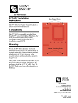
Distance and Thickness Measurement with Web Page Display
IMS5x00
Distance and Thickness Measurement with Web Page Display
Align the sensor vertically to the target object.
Then, move the sensor (or the target) closer, until you more or less reach the start of measuring range for your
sensor.
Once the object is within the sensor’s measuring range, the Range LED (green or yellow) on the front of the controller
will light up. Or, observe the FFT signal.
2
1
3
4
5
6
2
8
7
Measurement web page (distance measurement)

Page 17
Distance and Thickness Measurement with Web Page Display
IMS5x00
1
The LED visualizes the status of the transmission
of measured values:
- green: transmission of measured values is run-
ning.
- yellow: waiting for data in trigger mode
- gray: transmission of measured values stopped
Data queries are controlled by using the Play/
Pause/Stop/Save buttons of the measured val-
ues that were transmitted. Stop stops the diagram;
data selection and zoom function are still possible.
Pause interrupts recording. Save opens the Win-
dows selection dialog for file name and storage lo-
cation to save the FFT signals resp. measurement
values in a CSV file (separation with semicolon).
Click the button (Start), for starting the dis-
play of the measurement results.
2
Changes only take effect after clicking the Save
settings button.
3
In the window on the left, the signals can be en-
abled or disabled both during and after the mea-
surement. Inactive graphs are gray. Click on the
check mark to add them. The changes take effect
when saving the settings. Use the eye symbols
to show and hide the single signals. The calcula-
tion continues in the background.
• 01PEAK01: Chronological sequence of dis-
placement signal
4
Auto (= automatic scaling) or Manual
(= manual setting) allow for scaling the measure-
ment axis (Y axis) of the graphic.
5
The current values for distance, exposure time,
current measuring rate and time stamp are dis-
played in the text boxes above the graphic. Errors
are displayed as well.
6
Mouseover feature. When moving the mouse over
the graph, curve points are highlighted with a circle
symbol while the corresponding values are dis-
played in the text boxes above the graph.
7
X axis scaling: The total signal is zoomable with the
slider on the left side during running measurement.
The time range can be defined in the input field
below the time axis. If the diagram is stopped, you
can also use the right slider. The zoom window can
also be moved with the mouse in the center of the
zoom window (arrow cross).
8
The two buttons allow to switch between FFT sig-
nal and measurement representation.

Page 18
Data Output, Interface Selection
IMS5x00
Data Output, Interface Selection
The controller supports
- three digital interfaces that can be used in parallel for data output,
Ethernet: enables fast data transfer, but provides no real-time capabilities
(packet-based data transfer). Both measurement and FFT data can be
transferred. For measurement value detection without direct process con-
trol, for subsequent analysis. Parameterization is provided through the web
interface or ASCII commands.
RS422: provides an interface capable of real-time output at a lower data
rate.
Switching/limit value output
- Analog output: outputs either voltage or current values.
Selecting the required interfaces
for data output
Switch to the Settings > Outputs > Output interface menu
and select the desired output channels.
Ethernet
The controller transmits TCP/IP or UDP/IP packages with an Ethernet transfer rate of 10 Mbit/s or 100 Mbit/s. The
transfer rate is selected automatically depending on the connected network or PC.
When transmitting measurement data to a measurement server, following successful connection (TCP or UDP), the
sensor sends each measurement to the measurement server or to the connected client. No explicit request is neces-
sary for this.
Distance and thickness values are transmitted as 32 bit signed integer value with 10 pm resolution.

Page 19
Set IP Address
IMS5x00
Set IP Address
Change to the menu Settings > Outputs >
Ethernet Settings and enter the new IP ad-
dress.
Click on Apply settings to confirm.
Start the web interface with the new IP address.
Save the new device settings. Click on Save set-
tings.
Service, Repair
If the sensor, controller or sensor cable is
defective:
- If possible, save the current sensor settings in a pa-
rameter set to reload them into the controller after the
repair.
- Please send us the affected parts for repair or ex-
change.
If the cause of a fault cannot be clearly identified, please
send the entire measuring system to:
Liability for Material Defects
All components of the device have been checked and
tested for functionality at the factory. However, if defects
occur despite our careful quality control, MICRO-EPSI-
LON or your dealer must be notified immediately.
The liability for material defects is 12 months from deliv-
ery. Within this period, defective parts, except for wear-
ing parts, will be repaired or replaced free of charge, if
the device is returned to MICRO-EPSILON with shipping
costs prepaid. Any damage that is caused by improper
handling, the use of force or by repairs or modifica-
tions by third parties is not covered by the liability for
material defects. Repairs are carried out exclusively by
MICRO-EPSILON.
Further claims can not be made. Claims arising from the
purchase contract remain unaffected. In particular, MI-
CRO-EPSILON shall not be liable for any consequential,
special, indirect or incidential damage. In the interest
of further development, MICRO-EPSILON reserves the
right to make design changes without notification.
For translations into other languages, the German ver-
sion shall prevail.
MICRO-EPSILON MESSTECHNIK GmbH & Co. KG Tel. +49 (0) 8542 / 168-0
Koenigbacher Str. 15 info@micro-epsilon.de
94496 Ortenburg / Germany www.micro-epsilon.com

MICRO-EPSILON MESSTECHNIK GmbH & Co. KG
Koenigbacher Str. 15 · 94496 Ortenburg / Germany
Tel. +49 (0) 8542 / 168-0 · Fax +49 (0) 8542 / 168-90
[email protected] · www.micro-epsilon.com
Your local contact: www.micro-epsilon.com/contact/worldwide/
X9691389-A012090MSC
*X9691385-A03*
MICRO-EPSILON MESSTECHNIK
/