Mettler Toledo S9 Seven2Go™ pro DO Meter Operating instructions
- Category
- Measuring, testing & control
- Type
- Operating instructions

METTLER TOLEDO
Seven2Go pro
C
al
S9
Operating Instructions
Seven2Go™ pro DO Meter


Table of Contents
Introduction1 5
Safety Measures2 6
Definition of signal warnings and symbols2.1 6
Product specific safety notes2.2 6
Design and Function3 9
Overview3.1 9
Sensor connections3.2 9
T-Pad and hard keys3.3 9
Interface connection3.4 11
Display icons3.5 11
LED3.6 13
Acoustic signal3.7 13
Putting into Operation4 14
Scope of delivery4.1 14
Installing the batteries4.2 15
Installing power supply4.3 16
Connecting sensors4.4 17
Installing optional equipment4.5 18
Electrode holder4.5.1 18
Meter base stabilizing unit4.5.2 18
Wrist strap4.5.3 19
Switching the instrument on and off4.6 20
Instrument Setup5 21
Data storage5.1 21
Storage mode5.1.1 21
Storage destination5.1.2 21
System settings5.2 22
Language5.2.1 22
Time and date5.2.2 22
Access control5.2.3 22
Sounds and visuals5.2.4 23
User modes5.2.5 23
Power management5.2.6 24
Factory reset5.3 24
Instrument self-test5.4 24
DO Settings6 25
Calibration settings6.1 25
Calibration reminder6.1.1 25
Measurement settings6.2 26
Salinity compensation6.2.1 26
Barometric compensation6.2.2 26
Barometric unit6.2.3 26
Endpoint type6.3 27
Interval readings6.4 27
Temperature settings6.5 28
Measurement limits6.6 28
Table of Contents 3

IDs7 29
Sample ID7.1 29
User ID7.2 29
Sensor ID7.3 30
Sensor Calibration8 31
1-point calibration8.1 31
2-point calibration8.2 31
Sample Measurement9 32
Selecting a measurement unit9.1 32
Performing a DO measurement9.2 32
Data Management10 33
Data menu structure10.1 33
Measurement data10.2 33
Calibration data10.3 34
ISM data10.4 34
Data export to PC10.5 35
Maintenance11 36
InLab® OptiOx sensor maintenance11.1 36
Troubleshooting InLab® OptiOx11.2 36
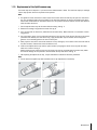
Replacement of the OptiOx sensor cap11.3 37
Interfering substances of the InLab® OptiOx sensor11.4 38
Software update11.5 38
Repair of the instrument11.6 38
Disposal11.7 38
Technical Data12 39
Product Portfolio13 40
Meter and kit versions13.1 40
Accessories13.2 40
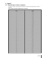
Appendix14 41
Dissolved Oxygen in relation to temperature14.1 41
Table of Contents4

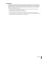
1Introduction
Thank you for purchasing this high quality METTLER TOLEDO portable meter. Everywhere you measure pH,
conductivity or dissolved oxygen - the Seven2Go™ portables are designed to offer you fast quality data, one-
handed operation and an investment that lasts. Whether you work in the laboratory, at-line or outdoors, the
Seven2Go™ meters will provide you with high quality measurement everywhere you go. The Seven2Go™
offers many exciting features, including:
●
Simple and intuitive menus that shorten steps needed for setting up measurements and calibration
●
T-pad hard keys for comfortable and fast navigation
●
Rubber side-guards for comfortable, one-handed operation
●
IP67 rating for the entire measurement system, including meter, sensor and the connection cables
●
Useful accessories such as the electrode clip, the meter base stabilizing unit, the wrist strap and the uGo™
carrying case with hermetically sealed interior for easy cleaning
5Introduction

2Safety Measures
2.1Definition of signal warnings and symbols
Safety notes are marked with signal words and warning symbols. These show safety issues and warnings.
Ignoring the safety notes may lead to personal injury, damage to the instrument, malfunctions and false results.
Signal words
WARNING for a hazardous situation with medium risk, possibly resulting in severe
injuries or death if not avoided.
CAUTION for a hazardous situation with low risk, resulting in damage to the device or
the property or in loss of data, or minor or medium injuries if not avoided.
Attention (no symbol)
for important information about the product.
Note (no symbol)
for useful information about the product.
Warning symbols
General hazard Toxic substance
Inflammable or explosive substance
2.2Product specific safety notes
Your instrument represents state-of-the-art technology and complies with all recognized safety rules, however,
certain hazards may arise in extraneous circumstances. Do not open the housing of the instrument; it does not
contain any parts that can be maintained, repaired or replaced by the user. If you ever have problems with your
instrument, contact your authorized METTLER TOLEDO dealer or service representative.
Intended use
This instrument is designed for a wide range of applications in various areas and is suitable
for measuring pH (S2, S8), conductivity (S3, S7) or dissolved oxygen (S4, S9).
The use therefore requires knowledge and experience in working with toxic and caustic sub
stances as well as knowledge and experience working with application-specific reagents,
which may be toxic or hazardous.
The manufacturer shall not be held liable for any damage resulting from incorrect usage
divergent to the operating instructions. Furthermore, the manufacturer`s technical specifica
tions and limits must be adhered to at all times and in no way exceeded.
Location
The instrument has been developed for indoor and outdoor operation and may not be used in
explosive environments.
Use the instrument in a location which is suitable for the operation, protected from direct sun
light and corrosive gases. Avoid powerful vibrations, excessive temperature fluctuations and
temperatures below 0°C and above 40°C.
6 Safety Measures

Protective Clothing
It is advisable to wear protective clothing in the laboratory when working with hazardous or toxic substances.
A lab coat should be worn.
Suitable eye protection such as goggles should be worn.
Use appropriate gloves when handling chemicals or hazardous substances, checking their
integrity before use.
Safety notes
WARNING
Chemicals
All relevant safety measures are to be observed when working with chemicals.
a) Set up the instrument in a well-ventilated location.
b) Any spills should be wiped off immediately.
c) When using chemicals and solvents, comply with the instructions of the producer and
the general lab safety rules.
WARNING
Flammable solvents
All relevant safety measures must be observed when working with flammable solvents and
chemicals.
a) Keep all sources of flame away from the workplace.
b) When using chemicals and solvents, comply with the instructions of the producer and
the general lab safety rules.
7Safety Measures

FCC Rules
This device complies with Part 15 of the FCC Rules and Radio Interference Requirements of the Canadian
Department of Communications. Operation is subject to the following conditions: (1) this device may not cause
harmful interference, and (2) this device must accept any interference received, including interference that may
cause undesired operation.
This equipment has been tested and found to comply with the limits for a Class A digital device, pursuant to
Part 15 of the FCC rules. These limits are designed to provide reasonable protection against harmful interfer
ence when the equipment is operated in a commercial environment. This equipment generates, uses, and can
radiate radio frequency energy and, if not installed and used in accordance with the instruction manual, may
cause harmful interference to radio communications. Operation of this equipment in a residential area is likely
to cause harmful interference in which case the user will be required to correct the interference at his own
expense.
8 Safety Measures

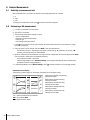
3Design and Function
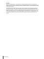
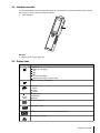
3.1Overview
9
8
11
10
8
1 Status LED (only Pro-series) 7 Rubber feet
2 Display 8 Fixing points for electrode holder
3 Calibration key 9 Micro-USB port (only Pro-series)
4 On/Off key 10 Battery compartment
5 Read key 11 Slot for wrist strap
6 T-Pad
3.2Sensor connections
1 Mini-LTW socket for digital
electrode
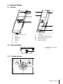
3.3T-Pad and hard keys
Cal
5
3
4
2
1
6
7
9Design and Function

In Standard Screen
Key Press and Release Press and hold
1 Read Start and manually stop a measure
ment
Activate/Deactivate uFocus™
2 Settings/Up Open setup menu ---
3 Store/Right Save last measurement data ---
4 Mode/Down Switch measurement mode ---
5 Recall/Left Recall measurement data ---
6 Cal Start calibration Recall last calibration result
7 On/Off --- Switch instrument on (hold for 1 sec
ond) or off (hold for 3 seconds)
In calibration mode (indicated by )
Key Press and Release Press and hold
1 Read Manually stop calibration
Save calibration result
Exit calibration mode
Activate/Deactivate uFocus™
2 Settings/Up --- ---
3 Store / Right --- ---
4 Mode/Down --- ---
5 Recall/Left --- Discard calibration result
6 Cal ---
7 On/Off --- ---
Settings and data menu
Key Press and release Press and hold
1 Read Select submenu
Confirm setting
Exit menu
2 Settings / Up Edit value (increase)
Navigate between menu points
Fast value increase
3 Store / Right Navigate between menu tabs
(only in top level per tab)
---
4 Mode / Down Edit value (decrease)
Navigate between menu points
Fast value decrease
5 Recall / Left Navigate between menu tabs
(only in top level per tab)
One level up (if not in top level)
Move left (in input fields)
One level up (if entering value into
input field)
6 Cal --- ---
7 On / Off --- ---
10 Design and Function

3.4Interface connection
The Micro-USB interface can be used for data transfer to a connected PC (LabX direct software) and for external
power supply. It is not possible to charge the batteries.
1 Micro-USB port
See also
●
Installing power supply (page16)
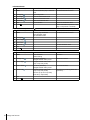
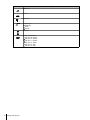
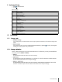
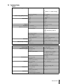
3.5Display icons
Icon Description
Power status
100% (fully charged)
75%
50%
25%
0% (fully discharged)
External power supply conected (USB)
USB-PC connection: LabX®direct
User mode
R
Routine
Expert
Outdoor
Storage mode
Automatic
Manual
Int
Interval Reading is on
GLP
GLP format is used
ISM sensor has been detected and is properly connected
Warning / Error occured
11Design and Function

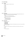
Icon Description
Sample ID
User ID
Sensor ID
A
Endpoint type
A
Automatic
T
Timed
M
Manual
Wait icon
Sensor cap life status:
Cap life > 6 months
Cap life > 3 months
Cap life > 1 months
Cap life > 2 weeks
Cap life > 2 days
Cap life < 2 days
12 Design and Function

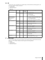
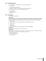
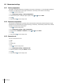
3.6LED
To use the LED, it has to be enabled in the instrument setup, see section Sounds and visuals (page23). The
LED indicates different information of the device:
●
Alarm Messages
●
Measurement endpoint
●
System Info
Instrument State LED green LED red LED
orange
Meaning
On for 5s
●
Instrument boot upInstrument turn ON
Blinking
●
Instrument has failed to boot correctly or fail
ure after booting
●
Error message appears
Instrument running
without calibration or
measurement in
progress
Blinking
●
Calibration has expired and user has defined
instrument to be blocked if sensor expires -
error message displayed
●
Any other error occurred and is displayed
Pulsing
●
Measurement in progress
Solid
●
Measurement complete
Measurement Mode
Blinking
●
Measurement outside limits
●
Error occured
Pulsing
●
Calibration in progress
Solid
●
Calibration complete
Calibration Mode
Blinking
●
Calibration not successful
●
Error occured
Pulsing
●
Data transfer in progress
Solid
●
Data transfer complete
Data Transfer
Blinking
●
Data transfer not successful
●
Error occured
Sleep Mode Solid
●
Meter in Sleep Mode
●
Press On/Off to re-activate meter
3.7Acoustic signal
To use the acoustic signals, they have to be enabled in the instrument setup (see section Sounds and visuals
(page23)). You can enable or disable the acoustic signal for the following features:
●
Keypress
●
Alarm Messages
●
Measurement endpoint
13Design and Function

4Putting into Operation
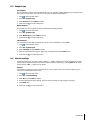
4.1Scope of delivery
Check the completeness of the delivery. The following parts belong to the standard equipment of your new
instrument. Further parts may be included depending on the ordered kit versions.
METTLER TOLEDO
Cal
S9 instrument
for DO measurement
Battery LR3/AA 1.5V
4pcs.
Meter base unit
Seven2Go
Operating Instructions
Test Report
many more
CD-ROM including operating instructions
USB-A to micro-USB cable for connection to PC,
length=1m
See also
●
Product Portfolio (page40)
14 Putting into Operation

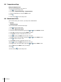
4.2Installing the batteries
1
2
1.
2.
4 x LR3/AA 1.5V
or 4 x HR6/AA 1.2V
3
4
5
6
15Putting into Operation

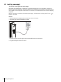
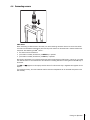
4.3Installing power supply
The instrument is not supplied with an AC adapter.
Alternatively, the instrument can be supplied by an external power supply unit (not included in the scope of
delivery) via the Micro-USB socket. Use an AC adapter that is suitable for all line voltages in the range of 100 to
240V, 50/60Hz and incorporates a USB socket. For connection, a suitable USB cable with an Micro-USB plug
is required.
While the instrument is powered by the external power supply, the batteries are not being used. The icon is
shown on the screen.
Attention
●
Take care that the AC adapter does not come into contact with liquids!
●
The power plug must be accessible at all times!
1 Connect the cable of the AC adapter with the Micro-USB socket of the instrument.
2 Plug the AC adapter into the wall socket.
16 Putting into Operation

4.4Connecting sensors
ISM
®
sensor
When connecting an ISM
®
sensor to the meter, one of the following conditions have to be met for the calibra
tion data to be transferred automatically from the chip of the sensor into the meter and is used for further mea
surements. After attaching the ISM
®
sensor ...
●
The meter must be switched on.
●
(If the meter is already switched on) the READ key is pressed.
●
(If the meter is already switched on) the CAL key is pressed.
We strongly recommend you to switch off the meter when disconnecting an ISM sensor. In doing so, you make
sure that the sensor is not removed while the instrument is reading data from or writing data to the ISM-chip of
the sensor.
The ISM icon appears on the display and the sensor ID of the sensor chip is registered and appears on the
display.
The calibration history, the initial certificate and the maximum temperature can be reviewed and printed in the
data memory.
17Putting into Operation

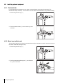
4.5Installing optional equipment
4.5.1Electrode holder
For a safe placing of the electrode you can mount an electrode holder on the side of the instrument. The
elctrode holder is part of delivery. You can mount it on either sides of the instrument for your personal handling.
1 Remove the protective clips (1).
1
2 Push the electrode holder (1) into the recess (2) of the
instrument.
1
2
4.5.2Meter base stabilizing unit
The meter base stabilizing unit should be mounted when using the instrument on a desk. It ensures a more firm
and secure stand when pressing the keys.
1 Remove the protective clips (1).
1
2 Push the meter base stabilizing unit (1) into the recess
es (2) of the instrument.
1
2
18 Putting into Operation

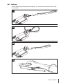
4.5.3Wrist strap
For better protection against damage caused by dropping, you can mount the wrist strap as shown in the fol
lowing diagrams.
M
E
T
T
L
E
R
T
O
L
E
D
O
M
E
T
T
L
E
R
T
O
L
E
D
O
O
L
E
D
O
1
2
O
L
E
D
O
M
E
T
T
L
E
R
T
O
L
E
D
O
M
E
T
T
L
E
R
T
O
L
E
D
O
M
E
T
T
L
E
R
E
T
T
L
E
R
M
E
T
T
L
E
R
T
O
L
E
D
O
M
E
T
T
L
E
R
T
O
L
E
D
O
O
L
E
D
O
3
M
E
T
T
L
E
R
T
O
L
E
D
O
M
E
T
T
L
E
R
M
E
T
T
L
E
R
T
O
L
4
19Putting into Operation

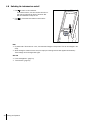
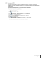
4.6Switching the instrument on and off
1 Press to switch on the instrument.
The firmware version, the serial number and the cur
rent date are displayed for about 5seconds. After
that the instrument is ready for use.
2 Press for 3seconds and release to switch off the
instrument.
EDO
Cal
Note
●
By default after 10 minutes not in use, the instrument changes to sleep mode. This can be changed in the
setup.
●
When starting the meter for the first time, the display for entering time and date appears automatically.
These settings can be changed later again.
See also
●
Power management (page24)
●
Time and date (page22)
20 Putting into Operation
Page is loading ...
Page is loading ...
Page is loading ...
Page is loading ...
Page is loading ...
Page is loading ...
Page is loading ...
Page is loading ...
Page is loading ...
Page is loading ...
Page is loading ...
Page is loading ...
Page is loading ...
Page is loading ...
Page is loading ...
Page is loading ...
Page is loading ...
Page is loading ...
Page is loading ...
Page is loading ...
Page is loading ...
Page is loading ...
Page is loading ...
Page is loading ...
-
 1
1
-
 2
2
-
 3
3
-
 4
4
-
 5
5
-
 6
6
-
 7
7
-
 8
8
-
 9
9
-
 10
10
-
 11
11
-
 12
12
-
 13
13
-
 14
14
-
 15
15
-
 16
16
-
 17
17
-
 18
18
-
 19
19
-
 20
20
-
 21
21
-
 22
22
-
 23
23
-
 24
24
-
 25
25
-
 26
26
-
 27
27
-
 28
28
-
 29
29
-
 30
30
-
 31
31
-
 32
32
-
 33
33
-
 34
34
-
 35
35
-
 36
36
-
 37
37
-
 38
38
-
 39
39
-
 40
40
-
 41
41
-
 42
42
-
 43
43
-
 44
44


Mettler Toledo S9 Seven2Go™ pro DO Meter Operating instructions
- Category
- Measuring, testing & control
- Type
- Operating instructions
Ask a question and I''ll find the answer in the document
Finding information in a document is now easier with AI
Related papers
-
Mettler Toledo SevenCompact™ S230 Operating instructions
-
-
-
-
-
-
-
-
-
Other documents
-
United States Stove MM0330 Owner's manual
-
 Hach sension8 User manual
-
Apera Instruments SX716 User manual
-
BANTE 820 User manual
-
EUTECH INSTRUMENTS DO 6PLUS DISSOLVED OXYGEN TEMP User manual
-
EUTECH INSTRUMENTS WD-35643-10 Owner's manual
-
Hanna Instruments HI98193 Owner's manual
-
 Ugo 85266894075 User manual
-
Traceable 6453 Owner's manual
-

