Page is loading ...

SevenCompact™ S210
English Operating Instructions
Français Mode d'emploi
Español Instrucciones de manejo


English
Operating Instructions
Français
Mode d'emploi
Español
Instrucciones de manejo


English
1
Introduction1 3
Safety Measures2 4
Installation3 6
Installing power supply3.1 6
Mounting uPlace™ electrode arm3.2 7
Connecting a sensor3.3 11
Operating the meter4 12
Backside layout4.1 12
Pin assignments RS232 connection4.1.1 12
The display4.2 13
Key controls4.3 15
Using the softkeys4.4 15
Selecting a measurement mode4.5 15
Navigating between menus4.6 16
Navigating within a menu4.7 16
Using the alphanumeric keypad4.8 16
Alphanumeric input4.8.1 16
Entering IDs / PIN4.8.2 17
Editing values in a table4.8.3 17
Calibration4.9 17
Running a one-point pH calibration4.9.1 18
Running a multi-point pH calibration4.9.2 18
Automatic buffer recognition4.10 18
Sample measurements4.11 18
Data transfer4.12 19
Temperature compensation4.13 20
Setup5 21
Menu structure of setup5.1 21
Sample ID5.2 21
User ID5.3 21
Stirrer5.4 22
Data Transfer Settings5.5 22
System settings5.6 23
Service5.7 25
Instrument self-test5.8 26
Menus and settings6 27
Menu structure of pH6.1 27
Sensor ID/SN6.2 27
Calibration settings6.3 27
Table of Contents
Table of Contents

Measurement settings6.4 28
Endpoint formats6.5 29
Timed Interval Readings6.6 30
Temperature settings6.7 30
Measurement limits6.8 30
Data management7 31
Menu structure of data menu7.1 31
Measurement data7.2 31
Calibration data7.3 32
ISM data7.4 33
Maintenance8 35
Meter maintenance8.1 35
Electrode maintenance8.2 35
Disposal 8.3 35
Error messages8.4 36
Error limits8.5 38
Sensors, solutions and accessories9 39
Specifications10 41
2 Table of Contents

English
3
1Introduction
Thank you for purchasing this METTLER TOLEDO instrument. The SevenCompact Series is not only a
new generation of intuitive and easy-to-operate bench meters for reliable measurements, they also
provide extra security against mistakes and support your workflow in the laboratory.
Mistakes can be reduced to a minimum because of the following characteristics:
●
New ISM
®
(Intelligent Sensor Management) technology: the meter automatically recognizes the
sensor and transfers the latest set of calibration data from the sensor chip to the meter. The last
five calibrations as well as the initial calibration certificate are also stored on the sensor chip.
These can be reviewed, transferred and printed. ISM
®
provides additional security and helps elimi
nate mistakes.
●
Multi-language graphical user interface on a large 4.3 inch display with intuitive menu guid
ance, making the operating instructions primarily a source of reference.
●
GLP and Routine mode for the needs of any operator: in the routine mode, the deletion of data is
prevented and changing those settings that would potentially jeopardize the collection of reliable
results, such as measurement settings, are blocked. This provides extra security for routine daily
work. Skilled workers are advised to employ the GLP mode to enjoy the instruments’ powerful full
functional range.
This instrument supports the workflow of a modern laboratory in all stages of the data collection and
archiving process:
●
The uPlace™ electrode arm can be operated with one hand and moves perfectly straight up and
down to bring the electrode in the perfect position for the best measurement performance. This
allows faster measurements and poses less risk to tip over the sample vessel and/or damage the
head of the sensor!
●
Only one keypress required: READ starts a measurement and CAL a calibration. It’s so easy!
●
Easy switching between the normal view and the uFocus™. The normal view has all the mea
surement parameters and IDs on the display to provide you an instant complete overview. In the
uFocus™ only the most important information is shown in large digits, such as measurement
value and temperature. This enables you to focus completely on the measurement, without getting
distracted by information that is not relevant to you.
●
Easy toggling with the MODE soft key between the various measurement parameters either
before or during a measurement.
●
Versatile data archiving options: print data, export data to a USB-stick, or send data to a PC with
LabX direct software!
●
Versatile data entry procedures: Enter sample / user and sensor IDs either directly on the instru
ment, or use a barcode reader or USB-Keyboard to increase efficiency.
At METTLER TOLEDO we are committed to providing you instruments of highest quality and we do all
we can to support you in maximizing the lifetime of your instrument:
●
IP54 rating – water and dust protection: we have designed our instrument in such way, that it
withstands drops of aqueous solutions on the housing and connections. This not only provides
extra protection, but also allows easy cleaning of the instrument with a damp cloth.
●
Rubber plugs and protective cover provide extra security against dust and spills of aqueous
solutions. Just keep the plug attached to the connections and cover the instrument with the trans
parent protective cover when not in use.
Have fun and many reliable measurements with our Seven Compact series of pH, Ion and conductivity
meters!
Introduction

4
2Safety Measures
Measures for your protection
Risk of explosion
●
Never work in an environment subject to explosion hazards! The housing of
the instrument is not gas tight (explosion hazard due to spark formation,
corrosion caused by the ingress of gases).
Risk of corrosion
●
When using chemicals and solvents, comply with the instructions of the pro
ducer and the general lab safety rules!
Measures for your operational safety
Caution
●
Always operate and use the instrument in accordance with the instructions
contained in this manual. The instructions for setting up your new instrument
must be strictly observed.
●
Do not open the instrument, it does not contain any parts which can be
maintained, repaired, or replaced by the user.
●
Have the meter serviced only by METTLER TOLEDO Service!
●
Any spillage should be wiped off immediately! Some solvents might cause
corrosion of the housing.
●
Avoid the following environmental influences:
•
Powerful vibrations
•
Direct sunlight
•
Atmospheric humidity greater than 80%
•
Corrosive gas atmosphere
•
Temperatures below 5 °C and above 40 °C
•
Powerful electric or magnetic fields
Safety Measures

English
5
FCC Rules
This device complies with Part 15 of the FCC Rules and Radio Interference Requirements of the Cana
dian Department of Communications. Operation is subject to the following conditions: (1) this device
may not cause harmful interference, and (2) this device must accept any interference received, includ
ing interference that may cause undesired operation.
This equipment has been tested and found to comply with the limits for a Class A digital device, pur
suant to Part 15 of the FCC rules. These limits are designed to provide reasonable protection against
harmful interference when the equipment is operated in a commercial environment. This equipment
generates, uses, and can radiate radio frequency energy and, if not installed and used in accordance
with the instruction manual, may cause harmful interference to radio communications. Operation of
this equipment in a residential area is likely to cause harmful interference in which case the user will
be required to correct the interference at his own expense.
Safety Measures

6
3Installation
Carefully unpack the meter. Keep the calibration certificate in a safe place.
3.1Installing power supply
The instrument is supplied with an universal AC adapter. The AC adapter is suitable for all line voltages
in the range of 100 to 240V, 50/60Hz.
Attention
●
Before operating, check cables for damage!
●
Ensure the cables are tidily arranged so that they cannot be damaged or interfere with the installa
tion!
●
Take care that the AC adapter does not come into contact with liquids!
●
The power plug must be accessible at all times!
1 Insert the correct connector plug into the AC adapter until it is completely inserted.
PUSH
2 Connect the cable of the AC adapter with the DC socket of the instrument.
3 Plug the AC adapter into the wall socket.
To remove the connector plug, push the release button and withdraw the connector plug.
Installation

English
7
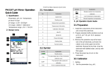
3.2Mounting uPlace™ electrode arm
The electrode arm can be used as stand alone or it can be attached to the instrument on the left or
right side, according to your preferences. The height of the electrode arm can be varied by using the
extension shaft part. Use the wrench to attach the extension part .
Installation

8
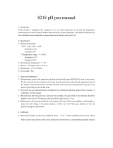
Assembly of the electrode arm
●
Use the wrench to attach the base to the electrode arm by tightening the screws. The electrode
arm can now be used in the stand alone mode.
Installation

English
9
●
To attach the electrode arm to the instrument, remove the plastic covers in a first step.
Installation

10
●
Then insert the foot of the meter to the arm base and shift the meter in the direction of the arrow to
make the foot fit.
●
Use the lock screw to attach the meter to the base of the arm.
Installation

English
11
3.3Connecting a sensor
To connect sensors, disconnect the rubber plug from the pH socket. Connect the electrode and make
sure that the plugs are properly inserted. If you are using an electrode with a built-in temperature probe
or a separate temperature probe, connect the other lead to the ATC socket. Twist the RCA (Cinch) plug
to ease the attachment of the sensor.
ISM
®
sensor
When connecting an ISM
®
sensor to the meter, one of the following conditions have to be met for the
calibration data to be transferred automatically from the chip of the sensor into the meter and is used
for further measurements. After attaching the ISM
®
sensor ...
●
The meter must be switched on.
●
(If the meter is already switched on) the READ key is pressed.
●
(If the meter is already switched on) the CAL key is pressed.
We strongly recommend you to switch off the meter when disconnecting an ISM sensor. In doing so,
you make sure that the sensor is not removed while the instrument is reading data from or writing data
to the ISM-chip of the sensor.
The ISM icon appears on the display and the sensor ID of the sensor chip is registered and
appears on the display.
The calibration history, the initial certificate and the maximum temperature can be reviewed and print
ed in the data memory.
Installation

12
4Operating the meter
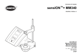
4.1Backside layout
a BNC socket for mV/pH signal input
b RCA (Cinch) socket for temperature signal input
c Reference socket for reference electrodes
d RS232 interface
e DC power supply socket
f USB A interface
g USB B interface
h Mini DIN socket for METTLER TOLEDO stirrer
4.1.1Pin assignments RS232 connection
Below the PIN assigments for the RS-232 interface are shown. To this interface can be connected
METTLER TOLEDO printers such as RS-P25.
Operating the meter

English
13
4.2The display
There are two modes for the display: the full-information screen with all the information on the display
and the measurement close-up screen (uFocus™) in which the measurement information is shown
with large font. Switching between these views is possible by pressing READ for 2 s, both during a
measurement or after/before a measurement.
5 6 2 3 4 1 7
20
19
23
17
18
13 14 15 16
8
10
9
21
12
11
5 6 2 3 4 1 7
21
19
20
23
22
9
8
10
9
12
11
13 14 8 15 16
Operating the meter

14
1 Measurement value
2 USB device connected
3 PC connected (for LabX direct)
4 Stirrer icon (when stirring is taking place)
5 Data logging icon (timed interval reading)
6 Routine mode icon (user access rights are restricted)
7 Date and time
8 Measurement temperature
9 Endpoint format
10 Temperature compensation
ATC: Temperature sensor con
nected
MTC: no temperature sensor
connected or detected
11 Number of data sets in memory
12 User ID
13 Softkey
14 Softkey
15 Softkey
16 Softkey
17 Sample ID
18 Sensor ID
19 pH electrode condition icon
Slope: 95-105%
Offset: ±(0-20)mV
Electrode is in good condition
Slope: 94-90%
Offset: ±(20-35)mV
Electrode needs cleaning
Slope: 89-85%
Offset: ±(>35)mV
Electrode is faulty
20 ISM
®
sensor connected
21 Stability criterion
Strict Medium Fast
22 Warning messages
23 Buffer groups or standards
Operating the meter

English
15
4.3Key controls
Key Press and release Press and hold for 2 seconds
Switch meter on Switch meter off
●
Start or end measurement
(measurement screen)
●
Confirm input or start edit
ing a table
●
Exit menu and go back to
measurement screen
Switch between measurement
close-up screen and full-infor
mation screen
Start calibration Review the last calibration data
Softkeys The function of the softkeys
varies from screen to screen
4.4Using the softkeys
The meter has four softkeys. The functions assigned to them change during operation depending on
the application. The assignment is shown on the bottom line of the screen.
In the measurement screen, the softkeys are assigned as follows:
Data Menu Mode
Access data menu Access meter settings Change measurement mode
The other softkey functions are:
Move one position to the right Edit Edit table or value
Move one position to the left End End calibration
Scroll up in the menu Yes Confirm
Scroll down in the menu No Reject
Increase value Review Review selected data
Decrease value Save Save data, setting or value
Scroll to next data set in memory Select Select the highlighted function or
setting
Delete letters or numbers on
alphanumeric keypad
Start Begin the reference measurement
Delete Delete selected data Trans Transfer selected data
4.5Selecting a measurement mode
Press the MODE softkey to switch between the different measurement modes.
The sequence of the alternating measurement modes is:
1. pH
2. mV
3. rel. mV
Operating the meter

16
4.6Navigating between menus
The meter display consists of a measurement frame, softkeys, areas for status icons and underlying
menu areas.
To access the menu areas and to navigate between them, use various softkeys (see "Using the soft
keys").
1 Press Menu.
The Setup menu appears and the pH tab is highlighted.
2 Press
to highlight the Setup tab.
— or —
Press
to highlight Sensor ID / SN.
3 Press EXIT to return to the measurement screen.
4.7Navigating within a menu
This example is based on the pH menu, but the procedure applies to the other menus as well.
1 Press Menu.
The Setup menu appears and the pH tab is highlighted.
2 Press
as often as needed to navigate to a menu item.
3 Press Select to move deeper in the menu for the chosen operation.
4 Continue navigating with
,
or Select until the final destination is reached within the
menu.
5 Press MODE/EXIT to go back to the previous menu.
— or —
Press READ to return to the measurement screen directly.
4.8Using the alphanumeric keypad
4.8.1Alphanumeric input
The meter has a screen keypad for entering IDs, SNs and PINs. Both numbers and letters are allowed
for these entries.
Note
●
When entering a PIN, each character entered will be displayed as ( * ).
Operating the meter
/