Coastal Shower Doors P22.66B-A Operating instructions
- Type
- Operating instructions

( 1 )
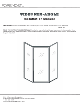
KEY
LETTER
A
B
C
c1
c2
c3
c4
c5
c6
c7
c8
c9
c10
PART
NUMBER
901
903
----
920
922
924
925
CP932
CP148TW
C921B
C960B
98-42
7-8114FHQ
DESCRIPTION
SILL
WALL JAMB
DOOR ASSEMBLY
Hinge Post
Hinge Stile
Strike stile
Rail
Hinge Pins (not shown)
Hinge Washer (not shown)
Hinge Sleeve (not shown)
Glazing Vinyl (not shown)
Magnetic Strip (not shown)
Door Panel Assembly Screws
QUANTITY
1
2
1
1
1
1
2
2
2
1
---
1
4
KEY
LETTER
D
E
F
G
H
I
J
K
L
M
N
PART
NUMBER
926
930
6114MSFHP
927
C176C
CP933
1329
6-8114PHP
638PHPT
98-42
CP903
DESCRIPTION
STRIKE POST
DOOR HANDLE (SET)
DOOR HANDLE SCREWS
DRIP RAIL
VINYL DOOR SWEEP
DRIP RAIL PLUG SET
PLASTIC SCREW ANCHOR
INSTALLATION SCREWS
ADJUSTMENT SCREWS
MAGNETIC STRIP
JAMB CAP
QUANTITY
1
1
2
1
1
1
6
6
8
1
2
FAX NO.
(904) 641-1697
Coastal Industries Inc.
P.O BOX 16091
JACKSONVILLE, FLORIDA 32245
TELEPHONE NO.
(904) 642-3970
Paragon Door
Installation Instructions
Explode View (standing outside of enclosure looking in) (left hand hinge shown)
PARAGON DR (OP36.70B-C) 06-17-2019
(R)

( 2 )
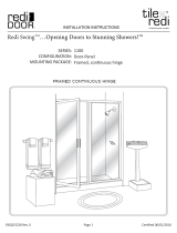
5. Decide on Door Swing (left or right)
Decide from which side your Door Assembly (D) is to hinge
(left or right) see Figure 3.
Insert Door Assembly’s Hinge Post (c1) into the Wall Jamb
from which it is to hinge.
Now, insert the Strike Post (D) into the other Wall Jamb (see
exploded view - sheet 1).
Magnet on door should face toward interior of enclosure, while
magnet on Strike Post should face toward the exterior.
Check door swing to make sure Door is swinging OUT and
NOT IN.
6. Attach Door Handle Assembly
Attach the Door Handles (E) to the Door Assembly using two(2)
Door Handle Screws (F) as shown in exploded view - sheet 1.
7. Adjust Unit Assembly
Adjust Door Assembly and Strike Post along curb as required
(see figure 4a).
In order for door to operate properly, Door Assembly (C) and
Strike Post (D) must be kept in vertical alignment (see
Figure 4b).
When satisfied with door operation, secure Hinge Post (c1)
and Strike Post (D) to the Wall Jambs (B) using six 638PHPT
Screws (L), (see Figure 4a) and exploded view - sheet 1.
1. Measure Base Opening
Measure the base opening along center of shower curb as
shown in Figure 1, then trim Sill (A) to 1/16” less than mea-
surement obtained.
2. Position Sill
With high lip toward exterior of enclosure, position Sill at cen-
ter of shower curb. Temporarily tape Sill to shower curb to
prevent movement.
3. Position and Plumb Wall Jambs
Place Wall Jambs (B) on to ends of Sill (A) and up against
shower walls as shown in Figure 2.
Plumb the Jambs, then pencil mark their installation holes lo-
cations on the shower walls (3 per jamb). Remove Wall Jambs.
Using a 3/16” drill bit (designed to drill through material you
are working with), drill 1” deep installation holes in locations
previously marked.
Insert Plastic Screw Anchors (J) into holes.
4. Secure Wall Jambs
Reposition Wall Jambs (B) as before and secure Jambs to walls
using the six(6) 1-1/4” Installation Screws (K) provided (3 per
jamb).
Now that Sill is secured beneath the Wall Jambs, remove the
tape used in step 2.
Figure 1
Figure 2
Figure 3
Figure 4a

( 3 )
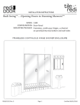
7. (continued)
8.
Notch Sweep & Insert into Drip Rail
Trim Vinyl Sweep one an a quater inch longer than the Drip
Rail, then Notch Vinyl Sweep (H) as shown in Figure 5a.
Attach a Drip Plug (I) to strike side of Drip Rail (G). Insert Vinyl
Sweep H) into Drip Rail (G) cavity and extend Vinyl Sweep
pass the Drip Rail edge as shown in Figure 5b.
9. Position and Secure Drip Rail
Figure 5a
Figure 4b
Figure 5b
9. (continued)
Clean bottom rail of door with alcohol to remove any oil. Fail-
ure to clean door rail prior to installation of Drip Rail (G) may
cause tape to release.
Remove backing from tape and position Drip Rail flush with
backside of Hinge Stile (c2) as shown in Figure 6a.
Sweep should cover gap at bottom of Door as shown in
Figure 6b.
Slightly elevate Drip Rail at strike side prior to securing so as to
create a sloping effect.
Two (2) optional self drilling screws (L) are provided to further
secure the drip rail. Never drill holes within 5/8” of exposed
glass!
10. Install Jamb Caps
After all adjustments have been made, install a Jamb Cap (N)
at both the hinge side and the strike side of the door as shown
in exploded view - sheet 1. Trim Caps to required lengths be-
fore installing as shown in Figure 7.
11. Leak Proof Installation
Run a bead of clear mildew resistant caulking down the full
length of each Wall Jamb outside where the Jambs meet the
Walls. Now run a bead outside where the Sill meets the curb.
Follow caulking manufacturer’s instructions before using shower
(normally 24 hours). Installation is now complete.
Figure 6a
Figure 6b
Figure 7
-
 1
1
-
 2
2
-
 3
3


Coastal Shower Doors P22.66B-A Operating instructions
- Type
- Operating instructions
Ask a question and I''ll find the answer in the document
Finding information in a document is now easier with AI
Related papers
-
Coastal Shower Doors P26.75N-A Installation guide
-
-
-
-
Coastal Shower Doors NPQFR33.75N-S Installation guide
-
-
-
-
Coastal Shower Doors HC4575IL.70N-C Installation guide
-
Other documents
-
 Foremost TDNA0570-OB-BN Installation guide
-
Swan SD00036OB.081 Installation guide
-
Aquatic L0041 Installation guide
-
 Redi Swing 11RCOFP04672 Installation guide
-
 Redi Slide 10RCPLP04772 Installation guide
-
Basco DLXH35A4672XPSV Installation guide
-
Basco DLXH60A1765OBOR Installation guide
-
-
-
Redi Slide 10ROPLD03270 Installation guide


