
TB-9021 Page 1 of 12
© 2017 DESCO NDUSTRIES, NC.
Employee Owned
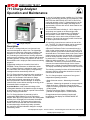
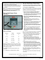
711 Charge Analyzer
Operation and Maintenance
USER GUIDE TB-9021
April 2017
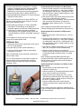
Figure 1. SCS 711 Charge Analyzer.
Description
The SCS 711 Charge Analyzer is an electronic test
instrument designed for ease of use. The lightweight
and compact construction oers great versatility in the
workplace. It can be used as a laboratory analytical
tool, evaluating the performance of ionizing equipment,
static-protective packaging, work surfaces and personnel
grounding systems. It is also very eective for use as a
demonstration tool in employee static awareness training
programs.
All parameter settings are controlled via a built-in
EEPROM. These parameters are defaulted to when
the 711 Charge Analyzer is switched on again. In case
of a malfunction, the unit will display a corresponding
message and then automatically switch o.
The 711 Charge Analyzer operation works according to
the eld mill-principle. The
eld meter is a parametric
ampli
er. An electrostatic eld induces a charge
on the sensor electrode, generating an AC current
that is proportional to the
eld strength. An amplier
measures this current without reducing the energy of the
electrostatic eld in average time.
Important Notice: Avoid extreme discharge of the
rechargeable batteries. If the batteries require charging,
do not allow the unit to sit idle for a period of time without
rst fully charging the batteries.
The 711 Charge Analyzer is powered by built-in
rechargeable NiMH-batteries or an AC wall plug-in
adaptor. When the unit is powered from the rechargeable
batteries, the LCD-display will not be back illuminated
to extend battery life. This power saving feature will
initiate within 60 seconds after the last measurement
or button depression. Also during battery operation,
the continuous LED-bar indication changes to a single
(momentary) action.
In case of a low battery power condition, the 711 Charge
Analyzer automatically switches o, rst displaying LOW
BATTERY then SWITCHING OFF UNIT. If this occurs,
continued operation of the 711 Charge Analyzer can be
maintained through the AC adaptor. Recharge time is
approximately 14 hours with unit o, when batteries are
fully discharged.
Two vertical LED bars indicating 0 - 100% charge level
and polarity are located on the left and right sides
of the front panel. The alphanumeric LCD-display is
the information center of the 711 Charge Analyzer
and allows the user to observe the principles of static
protection. The unit’s high accuracy makes it well suited
for product performance analysis.
All interfacing connections are made at the rear of the
unit. The SCS 711 Charge Analyzer can be connected
to a y (t)-recorder via the ± 2 volts analog output.
A Remote Field Sensor Probe is connected through a
4-Pin circular socket located on the rear of the unit. The
sensor operates on the same measurement principle as
described above. This feature allows to the user to make
measurements by means of a hand-held or xed position
probe in remote locations, where it may be impossible
to position the 711 Charge Analyzer. Measurement
distances with the probe are 1, 2, 5, 10 and 20
centimeters. The built-in microprocessor automatically
converts the measured eld strength via the chosen
distance into a charge of an equivalent potential in volts.
The display automatically switches from volts to kilovolts.
The following operating functions will be automatically
activated, when the appropriate electrode or sensor is
connected to the base unit.
The 711 Charge Analyzer comprises of four types of
independent operating functions:
• Static eld meter sensor – Measuring electrostatic
elds
• Voltmeter - Measuring the potential on charged objects
• Static decay time – Measuring charge-decay and
balance of ionizing equipment by charge plate monitor
(CPM) method
• Remote Field Sensor Probe – Measuring the
potential on charged objects in conned areas.
Change between these operating functions will
be veried on the display as CHANGE MODE OF
OPERATION.
Test Equipment Depot - 800.517.8431 - 99 Washington Street Melrose, MA 02176
TestEquipmentDepot.com

TB-9021 Page 2 of 12
© 2017 DESCO NDUSTRIES, NC.
Employee Owned
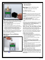
Packaging
1 Charge Analyzer
1 Plate Electrode
1 Cup Electrode
1 Cylinder Electrode
1 Sensor Red Cover
1 Measuring Lead, 1m
1 Conductive Container with Insulating Handle
1 Insulated Bulldog Clip
3 Metal Spacers with Thread, 76 mm (3 in.) Length
1 Field Sensor Probe with 2 m Cable & Red Cover
1 Power Adapter, 12VDC
1 Carrying Case
1 Certicate of Calibration
Specications
Description Typical Value
Dimensions
Base unit: (6 x 6 x 6) inches
(152 x 152 x 152) mm
Weight
1.8 kg (4 lbs.)
High Voltage Cascade
Built-in NiMH-rechargeable
batteries,1400 mAh -
Recharge time approximately
14 hours (unit o) when
batteries are fully discharged.
AC adapter: secondary side,
12VDC/500 mA
Operating Time
(rechargeable batteries)
4 hours (approx.) with full
charge.
Accuracy
± 10 % of range end value
(digitized)
Operating Functions
CPM (positive/negative/
automatic), Voltmeter, and
Field meter
Interfaces
Analog output ± 2V (± 1 V, in
500V range for voltmeter).
Input to output ratio in
Voltmeter Mode: 25VDC
= 12.5 to 1, 100VDC =
50 to 1, 500VDC = 500 to
1, 1,000VDC = 500 to 1,
5,000VDC = 2500 to 1.
Remote Field Sensor
Probe
34 mm diameter - 190 gms
(6.7 oz.)
Displays
Two, 11-segment positive
& negative LED-bar
charge indicators 16-digit
alphanumeric dual row LCD
Settings: CPM -
Operating Function
Starting voltage: 600V -
1200V in 1V-steps
Stop voltage: 1V - 500V in
1V-steps
(in decimal mode)
Static Decay Time
0.1 seconds - 99.9 seconds
Oset-voltage Time
0 seconds (Indenite time,
CPM in oating mode)
1 - 10 seconds (1 second
steps)
10 - 60 seconds (10 second
steps)
Voltmeter Operating
Function
Ranges: 25V, 100V, 500V, 1.0
kV, 5.0 kV and auto range
Fieldmeter Operating
Function
Ranges: Manual 1.25 kV/m,
5 kV/m, 25 kV/m, 50 kV/m,
250 kV/m, and automatic
Plate Electrode
VA-steel (152 x 152) mm/
(6 x 6) inches, removable,
capacitance (20 ± 2) pF
Cup Electrode Gold-plated electrode with
4 mm-banana socket, for
voltage measurements
Selection of Operarting
Function
Pre-setting is "FIELD
METER", additional
automatic settings by
applying the plate or cup
electrode

TB-9021 Page 3 of 12
© 2017 DESCO NDUSTRIES, NC.
Employee Owned
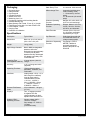
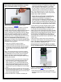
Field Meter Operation
Figure 2. SCS 711 Charge Analyzer Field Meter
Operation.
Kilovolts/Meter Measurement Ranges: Manual/Auto;
1.25 kV/m, 5.0 kV/m, 25 kV/m, 50 kV/m, & 250 kV/m
Meter display symbols in Field meter mode.
F = SCS 711 Charge Analyzer in Field meter mode
(upper left corner).
R = Kilovolts/Meter measurement range (kV/m) selected.
AR = Auto voltage measurement range selected (arrow
symbol will briey ash in lower left corner before symbol
appears. Arrow symbol will briey ash during overow
condition when in the auto range).
E = Electrical eld strength (V/meter) as measured. If
range selected is too low OVERFLOW will appear.
Field Meter Operation Setup
Warning:
To reduce the risks associated with hazardous voltage:
• Connect the attached ground wire on rear panel to an
electrical ground before operating the 711 Charge
Analyzer
• Do not use if the 711 Charge Analyzer housing or
power supply are damaged;
• Do not attempt to modify or repair – no user
serviceable parts inside – contact SCS Service for
repair.
To reduce the risks associated with re or explosion:
• Do not operate the 711 Charge Analyzer in an
explosive environment. The 711 Charge Analyzer is not
designed to be intrinsically safe.
1. Ground the Charge Analyzer 711 by attaching the
ground wire with alligator clip on the rear panel of the
unit to an earth/electrical ground.
2. Remove the plate electrode (b) from the Charge
Analyzer 711 if attached.
Note: If the unit is ON at this time, the display will briey
indicate CHANGE MODE OF OPERATION then FIELD
METER IS ENABLED.
3. Press the on/o button to activate the SCS 711
Charge Analyzer.
4. Cover the measurement electrode on the top of the
unit with the red sensor cover (e).
5. Select each range by pressing the “A” button
RANGE momentarily. Be sure to allow a brief moment
between each range selection to perform the zeroing.
This completes the zeroing of all ranges.
Field Meter Use
1. Remove the red sensor cover (e) from the
measurement electrode.
2. Select the desired voltage range by pressing the “A”
button.
Note: If OVERFLOW appears during the measurement
select a higher range
The SCS 711 Charge Analyzer is now ready to measure
electrostatic elds on objects such as tapes, lms,
plastic objects, etc., indicating in kilovolts per meter.
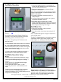
Figure 3. Testing Low Tribocharging Tapes.
Demonstration #1 Testing of Low Tribocharging
Tapes: With the Charge Analyzer 711 in the Field meter
operating mode, pull the tape o the roll and hold it
above the sensor. The digital display reads the eld
Test Equipment Depot - 800.517.8431 - 99 Washington Street Melrose, MA 02176
TestEquipmentDepot.com

TB-9021 Page 4 of 12
© 2017 DESCO NDUSTRIES, NC.
Employee Owned
strength in kV/m. To convert readings of kV/m into volts
use the following formulas:
R/100 x D (cm) or R/39.37 x D (in.) Where: R = Reading
indicated on the display and D = Distance between
tape and sensor electrode, measured in centimeters or
inches.
Example 1: If reading on the display of the Charge
Analyzer 711 is 200 KV/m and the distance to the sensor
electrode is 5 cm, the voltage on the tape is calculated
by: 200/100 x 5 = 10 Kilovolts.
Example 2: If reading on the display of the Charge
Analyzer 711 is 50 KV/m and the distance to the
sensor electrode is 3 inches, the voltage on the tape is
calculated by: 50/39.37 x 3 = 3.8 Kilovolts.
Note: Properly performing ESD control tapes must
minimize charging when unwound from the carrier roll.
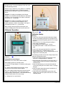
Voltmeter Operation
Figure 4. SCS 711 Charge Analyzer Voltmeter
Operation.
Voltage Measurement Ranges:
Manual/Auto; 25V, 100V, 500V, 1000V, & 5000V
Meter display symbols in Voltmeter mode
V = SCS 711 Charge Analyzer in Voltmeter mode (upper
left corner).
R = Voltage measurement range selected. If range
selected is too low OVERFLOW will appear.
AR = Auto voltage measurement range selected (arrow
symbol will briey ash in lower left corner before
symbol appears. Arrow symbol will briey ash during
overow condition when in the auto range.
U = Voltage level on cup electrode.
→
→
Figure 5. SCS 711 Charge Analyzer Voltmeter Operation
(Back of Unit).
Voltmeter Setup
Warning:
To reduce the risks associated with hazardous voltage:
• Connect the attached ground wire on rear panel to an
electrical ground before operating the SCS 711 Charge
Analyzer;
• Do not use if the 711 Charge Analyzer housing or
power supply are damaged;
• Do not attempt to modify or repair – no user
serviceable parts inside – contact SCS Service for
repair.
To reduce the risks associated with re or explosion:
• Do not operate the 711 Charge Analyzer in an
explosive environment. The 711 Charge Analyzer is not
designed to be intrinsically safe.
The following procedure zeros each voltage range in the
Voltmeter measurement mode.
1. Remove the plate electrode and red sensor cover
from the 711 Charge Analyzer, if attached.
2. Mount the gold cup electrode (a) to the top of the 711
Charge Analyzer and secure with the attached long-
knurled screws.
3. Insert the banana plug on one end of the lead wire
(f) into the ground jack on the back of the 711 Charge
Analyzer.
4. Insert the other banana plug end of the lead wire (f)
into the gold cup electrode (a).
5. Ground the unit by attaching the ground wire with
alligator clip on the rear panel of the unit to an earth/
electrical ground.

TB-9021 Page 5 of 12
© 2017 DESCO NDUSTRIES, NC.
Employee Owned
6. Press the on/o button to activate the 711 Charge
Analyzer. The display will briey indicate CHANGE
MODE OF OPERATION then VOLTMETER IS
ENABLED (if cup has not been previously attached).
7. Press the “B” button (SET) to display OFFSET A.
8. Select OFFSET A by pressing the “A” button to display
UPDATE OFFSET menu.
Note: If you should press the “B” button (SETUP), you
will have to switch o the Charge Analyzer 711 to get
back into the Voltmeter mode.
9. Select YES by pressing the “A” button. GROUND
CUP, READY >B will appear on the display for
verication that the cup electrode is indeed grounded.
10. Select the “B” button to activate the automatic
zeroing feature in the Voltmeter mode. Display will
indicate READ ALL OFFSET, UPDATING, zeroing all
ranges.
This completes the zeroing procedure. The display
returns to the measurement mode.
Voltmeter Use
1. Unplug the lead (f) from the ground jack at the rear of
the 711 Charge Analyzer.
2. Plug the lead (f) into the cylinder electrode (c).
3. Select the desired voltage range by momentarily
pressing the “A” button.
Note: If OVERFLOW occurs during the measurement
select a higher range.
The 711 Charge Analyzer is now ready to monitor the
eectiveness of static control products, measuring
electrical charge on people and conductive objects,
indicating in volts.
Figure 6. Performance of a Wrist Strap.
Demonstration #2 Performance of a Wrist Strap
1. Hold the cylinder electrode in one hand and perform
normal body movements (e.g., sitting down, standing
up, walking back and forth, etc.), experienced in the
work environment. Observe voltage variations on the
SCS 711 Charge Analyzer.
2. Now attach a static control wrist strap to the arm and
connect to an earth/electrical ground as
recommended by the manufacturer. Perform the same
body movements and observe the reduced or
eliminated voltage variations on the 711 Charge
Analyzer.
Note: Properly performing ESD control tapes must
minimize charging when unwound from the carrier roll.
Demonstration #3 Performance of ESD Control
Flooring
1. Stand on a non-static control ooring (e.g., mat, tile,
epoxy, etc.).
2. Hold the cylinder electrode in one hand and perform
normal body movements (e.g., sitting down, standing
up, walking back and forth, etc.), experienced in the
work environment. Observe voltage variations on the
711 Charge Analyzer.
3. Now stand on a static control ooring (e.g., mat, tile,
epoxy, etc.) using ESD control footwear/straps.
4. Hold the cylinder electrode in one hand and
perform some body movements and observe reduced
or eliminated voltage variations on the 711 Charge
Analyzer.
Note: Properly performing ESD control ooring in
conjunction with ESD control footwear/straps must be
able to minimize and quickly drain electrical charges
developed by a person.
Demonstration #4 Performance of a Static Control
Work surface
1. Plug the lead (f) into the banana jack on the
conductive container (h).
2. Hold the container by insulating handle being careful
not to contact the sides of the container.
3. Charge yourself up by rubbing your feet on a non-
static ooring material and touch the container with
other hand to charge it. Notice the level of charge on
the SCS 711 Charge Analyzer.
4. Contact an ESD control work surface with the
container and observe the voltage reduction and
removal.
Note: Properly performing conductive containers must
be able to quickly drain a charge from their surface when
ESD control surface.
Test Equipment Depot - 800.517.8431 - 99 Washington Street Melrose, MA 02176
TestEquipmentDepot.com

TB-9021 Page 6 of 12
© 2017 DESCO NDUSTRIES, NC.
Employee Owned
Figure 7. Performance of a Static Control Worksurface.
Demonstration #5 Discharge Performance of Static
Control Packaging Material
1. Place a packaging material on top of a grounded
static control work surface.
2. Charge up the conductive container as described
above in Demonstration #4 and contact the top of the
packaging material with the charged container.
Observe the amount of charge draining through the
packaging material on the 711 Charge Analyzer.
Note: Properly performing packaging materials must be
able to quickly drain a charge from their surface when
placed on an ESD control surface.
Static Decay Time and Balance
Operation
Figure 8. SCS 711 Charge Analyzer Static Decay Time
and Balance Operation.
Voltage Decay Ranges:
Start: 600 to 1100 volts
Stop: 1 to 500 volts
Meter display symbols in Static Decay mode:
TIMER = Mode
000V-000V = Start & stop voltage range
U = Voltage level on plate
OFFS-TIME = Oset time in seconds
Warning:
To reduce the risks associated with hazardous voltage:
• Connect the attached ground wire on rear panel to
an electrical ground before operating SCS 711 Charge
Analyzer.
• Do not use if the 711 Charge Analyzer housing or
power supply are damaged;
• Do not attempt to modify or repair – no user
serviceable parts inside – contact SCS Service for
repair.
To reduce the risks associated with re or explosion:
• Do not operate the 711 Charge Analyzer in an
explosive environment. The 711 Charge Analyzer is not
designed to be intrinsically safe.
Static Decay Time and Balance Setup
The following procedure zeros each voltage range,
adjusts the start and stop voltage, and adjusts the oset
time in the Static Decay Time measurement mode.
Note: You must remove the charge plate to change to
Field meter mode to perform the following procedure.
Voltage range zero procedure:
Perform zeroing on rst power up.
1. Ground the Charge Analyzer 711 by attaching the
ground wire with alligator clip on the rear panel of the
unit to an earth/electrical ground.
2. Remove the plate electrode (b) from the Charge
Analyzer 711.
3. Press the on/o button to activate the Charge
Analyzer 711. The display will briey indicate
CHANGE MODE OF OPERATION then Field meter IS
ENABLED.
4. Cover the measurement electrode on the top of the
unit with the red sensor cover (e).
5. Select each range by pressing the “A” button RANGE
momentarily. Be sure to allow a brief moment between
each range selection to perform the zeroing. This
completes the zeroing of all ranges.
Setting the START & STOP voltage:
Note: The Start voltage can only be adjusted from 600 to
1100 volts. The Stop voltage can only be adjusted from
1 to 500 volts. The maximum period of time that the 711
allows for the measurement of the start to stop voltage is
99.9 seconds.

TB-9021 Page 7 of 12
© 2017 DESCO NDUSTRIES, NC.
Employee Owned
1. Press the “B” button (SET) to display SETUP B.
2. Press the “B” button to display the START 600-1100
voltage range menu.
3. Notice the blinking cursor under the thousandths
position of the four-digit voltage value located on the
second line of the display. Change the value of this
digit by pressing the “A” button momentarily.
4. Press the “B” button once to move the cursor to the
next digit and adjust the value (0-9) with the “A”
button.
5. Continue adjusting the value of the remaining digits
to the desired level. If you make a mistake continue to
press the “A” & “B” buttons consecutively to obtain the
desired value.
6. When the desired voltage value is obtained, continue
to press the “B” button until the display reads A<YES
& NO>B.
7. Press the “A” YES button to verify and store the start
voltage value. Pressing the “B” NO button repeats the
voltage value setting menu again.
8. The STOP 1-500 voltage range menu is now
displayed. Adjust the stop voltage using the “A” &
“B” buttons as described in the Start voltage
procedure above.
9. Press the “A” button YES to verify and store the stop
voltage value. Pressing the “B” NO button repeats the
voltage value setting menu again.
Note: If you should select a start or stop voltage
outside of the ranges listed above, the SCS 711
Charge Analyzer will not store that value. If the charge
plate does not reach the set stop voltage within 99.9
seconds the counter stops and the display ashes TIME
EXCEEDED. This message will appear in Positive,
Negative, and Auto decay modes.
Setting the Oset Time: When the start and stop
voltage procedure is completed the OFFSET menu will
be displayed. The oset time can be adjusted from 0
(Indenite time), 1 to 10 seconds (1-second steps), and
10 to 60 seconds (10-second steps). To change the
oset time perform the following steps:
1. Press “A” CHANGE button repeatedly to move
through time settings.
2. When the desired time is set, press the “B” OK button
to store. The start and stop voltage values with the
oset time value will then be displayed momentarily.
3. Next the display will indicate TIMER+ OFFSET OK.
If values are correct, press the “A” YES button. If
not, press the “B” NO button which will restart the start
voltage menu.
4. The display will then indicate CLEAR MEMORY if
changes were made. Press the “A” YES button to
store the revised settings. PARAMETER CHANGED
will momentarily appear. If no changes were made,
display will indicate PARAMETER NOT CHANGED.
Note: To measure oset balance for time periods longer
than 60 seconds, set oset time to zero seconds “0 s”.
This puts the Charge Analyzer CPM in a oating mode
for an indenite time period. The unit will not have an
active timer in this mode. Elapsed time must be recorded
by the operator using a stop watch or other time
recording device. Connection to the analog output using
a chart recorder e.g. allows for monitoring of the oset
voltage during long time periods. Pressing the “B” button
twice during the indenite oset time mode returns the
display to the DECAY TIME/START mode.
This completes the voltage range zeroing, start/stop
voltage, and oset time setup.
Static Decay Time and Balance Use
1. Remove the red sensor cover from the measurement
electrode.
2. Mount the plate electrode (b) to the 711 Charge
Analyzer. Be sure that the red sensor cover (e) is
removed from the sensor electrode. Display will
indicate DECAY TIME, voltage polarity (“Either” POS,
NEG, or AUTO) and PRESS START.
3. Press the “A” MODE button to select Positive,
Negative, or Auto (Positive & Negative) decay.
Note: In AUTO mode there will be an approximate 5
seconds delay between positive & negative decay tests.
4. The display will now indicate DECAY TIME: POS,
NEG, or AUTO on the rst line and PRESS START on
the second line.
5. Pressing the “A” YES button again after AUTO decay
is displayed will select the READ OFFSET CPM
menu. Pressing the “A” YES button will initiate the
system verication and the display will respond with
UPDATING.
Note: System verication (Zero point adjustment) is
only recommended before the rst measurement, when
parameters are rst set with the attachment of the plate
electrode. If the “B” button (NO) is pressed you will
return to the start of the DECAY TIME menu.
The SCS 711 Charge Analyzer is now ready to measure
static charge neutralization eectiveness and the oset
balance of ionizers.
Test Equipment Depot - 800.517.8431 - 99 Washington Street Melrose, MA 02176
TestEquipmentDepot.com

TB-9021 Page 8 of 12
© 2017 DESCO NDUSTRIES, NC.
Employee Owned
Demonstration #6 Charge Plate Monitor and Static
Decay Time Measurements – Air Gun Ionizer
indicate the following: OFF (Maximum voltage oset
observed during oset time period), T (Set oset
time), and NEG. or POS. DECAY (Time to reach
the stop voltage). In the Auto mode both positive and
negative decay time will alternately be displayed.
Note: If the charge plate does not reach the set stop
voltage within 99.9 seconds the counter stops and the
display ashes TIME EXCEEDED.
6. Shortly after the measurement is completed, the
display will alternately indicate the decay time test
results and A<CONTINUE. Pressing the “A”
(Continue) button will display the SAVE VALUES
menu. Selecting “A” (YES) button will allow saving of
the static decay time measurement test data into a le
location numbered 01 - 99. Press the “B” (OK) button
to store the data in the displayed le number location.
To store data in a previously used le location number,
press the “A” (Change) button. File locations can be
changed in steps of ten using the “A” button or in steps
of one within an indicated decade, by using the “B”
button. Once you have selected the previously used le
location press the “B” (OK) button to store the data. The
display will then indicate that the le selected is about to
be overwritten by OVERWRITE NO. Select button “A”
YES to proceed. The display will then briey indicate
Please Wait Saving and then return to the DECAY TIME/
START menu.
If after performing a static decay time measurement
and storing of the test data is not required, press the “B”
button. The display will briey indicate BREAK and then
return to the DECAY TIME/START menu.
Demonstration #7 Charge Plate Monitor and Static
Decay Time Measurements – SCS Ionized Air Blower
Figure 10. Charge Plate Monitor and Static Decay Time
Measurements Using 963E Ionized Air Blower.
1. Attach the three metal-spacers (j) by screwing into
the three locations at the rear of the SCS 711 Charge
Analyzer.
Figure 9. Charge Plate Monitor and Static Decay Time
Measurements using 980/980E Air Gun Ionizer.
Static neutralization (the ability to reduce or eliminate
a charge on a surface) is an important quality for
ionizers. Static decay time is dened as the time interval
needed to reduce a dened voltage potential on an
object to a dened lower potential by means of applied
ionized air. Another important aspect for ionizers is the
ability to produce a balanced stream of positive and
negative ions. The 711 Charge Analyzer can be used to
accurately measure both of these parameters.
Note: For more detailed information on measuring the
performance of ionizers refer to the ESD standard ANSI/
EOS/ESD-S3.1 for Protection of Electrostatic Discharge
Susceptible Items-Ionization.
1. Press the “B” (START) button to charge
the plate and begin the measurement menu.
2. On the rst line the selected start and stop voltages
are indicated. On the second line, the plate default
charge-voltage is indicated (approximately 1200
volts).
Note: If the charge plate does not retain the applied
voltage it may be due to a high level of room humidity
or contamination on one or more of the four spacers.
Spacers should be cleaned with laboratory grade
alcohol. Use clean cotton or latex gloves when directly
handling these spacers.
3. Position the ionizing air gun above the charge plate
and activate the air gun blowing ionized air at the
plate. The timer in the 711 Charge Analyzer will
begin counting (in 1/10’s of seconds) when the set
start voltage is reached on the plate. At this time the
display will indicate TIMER (present timer count in
seconds) and U (present voltage level on the charge
plate).
4. When the stop voltage is reached, the unit will begin
the oset time (ionizer balance) mode. The display will
indicate OFFS-TIME (starting timer at set time) and U
(current charge plate voltage).
5. When the oset time is complete, the display will

TB-9021 Page 9 of 12
© 2017 DESCO NDUSTRIES, NC.
Employee Owned
2. Position the 711 Charge Analyzer in front of the ionizer
blower with the display facing upward.
3. Measure the static decay rate and oset balance by
following the procedure outlined in Demonstration
#6 above.
Note: For more detailed information on measuring the
performance of ionizers refer to the ESD standard
ANSI/EOS/ESD-S3.1 for Protection of Electrostatic
Discharge Susceptible Items-Ionization.
Remote Field Sensor Probe
Operation
Figure 11. Remote Field Sensor Probe Operation.
Measurement Ranges:
Distance Voltage Resolution
1 cm 0 to 10kv 1V
2.5 cm 0 to 20vk 2V
5 cm 0 to 50vk 10V
10 cm 0 to 100vk 10V
20 cm 0 to 200vk 20V
Display automatically converts from volts to kilovolts.
Meter display symbols in Remote Field Sensor Mode:
“EFM” = SCS 711 Charge Analyzer in External Field
mode (upper left corner).
“D” = Distance between probe and surface to be
measured.
“U” = Voltage level on charged surface or object.
Remote Field Sensor Probe Setup
The following procedure activates the SCS 711 Charge
Analyzer for use with the Remote Field Sensor Probe.
1. Turn o the 711 Charge Analyzer.
Note: If the plate electrode is not attached to the Charge
Analyzer 711, place the red cover over the measurement
electrode to prevent accidental damage.
2. Insert the 4-Pin plug (observing keyed position at
bottom of socket) of the Remote Field Sensor
Probe cable into the 711RS socket on the rear of the
711 Charge Analyzer Tighten the outer shell onto the
socket (clockwise motion), until secured.
3. Ground the unit by attaching the ground wire with
alligator clip on the rear panel of the unit to an earth/
electrical ground.
4. Press the on/o button to activate the SCS 711
Charge Analyzer. The display will briey indicate
RECEIVED DATA WAIT.
5. The display will next indicate EXTERN EFM, A<OFF &
ON>B. Press the “B” button (ON) to activate the
Remote Field Sensor Probe. Selecting the “A”
button (OFF) will deactivate the sensor and return the
711 Charge Analyzer to an internal measurement
mode.
6. When ON is selected the display will indicate EXT.
EFM, D = CM, A<CHANGE, & OK>B. Select the
desired measurement distance by pressing the “A”
button (CHANGE) momentarily until desired distance
is displayed.
Note: This value represents the distance in centimeters
between a charged surface and the sensor head.
7. Press the “B” button (OK) to select. The display will
briey indicate PARAMETER CHANGED when
distance value is changed.
8. The display now indicates external eld mode,
distance, and measured voltage. To change the
distance setting again while in the external eld mode,
press the “B” button momentarily and repeat steps
5-7.
9. With red cover on probe, zero the SCS
Remote Field Sensor Probe by inserting a small
probe or tool into the hole located at the rear of the
sensor. At the bottom of the hole there is a membrane
switch. Momentarily apply light pressure to activate
the zeroing feature. The 711 Charge Analyzer display
will briey indicate ZERO ADJUSTMENT.
Note: When changing to a lower distance setting, re-
zeroing is recommended. For higher distances it is not
necessary to re-zero.
This completes the Remote Field Sensor Probe setup
and zeroing.
Test Equipment Depot - 800.517.8431 - 99 Washington Street Melrose, MA 02176
TestEquipmentDepot.com

TB-9021 Page 10 of 12
© 2017 DESCO NDUSTRIES, NC.
Employee Owned
Remote Field Sensor Probe Use
Important Notice: When measuring an unknown
voltage on a surface, position the probe at a far distance
away and approach the surface slowly to prevent
accidental discharges to the sensor element. If there is
a suspected high charge or if the surface of the object is
uneven, the measuring distance should be increased.
1. Remove the red cover from the Remote Field
Sensor Probe.
2. Position the sensor in front of the charged surface or
object to be measured.
3. Observe the measured voltage (U = Volts or Kilovolts)
on the 711 Charge Analyzer display.
Note: The Remote Field Sensor Probe measures the
electrical eld in V/m. The electrical eld is measured
automatically based on the set measurement distance
and is then internally calculated and indicated as volts in
the displayed U = V.
Example 1: If the distance between the object and
sensor equals 2.5 cm and the “U” value indicates 500
volts, then the strength of the electric eld is in this case
500V/inch (Since 1 inch = 2.5 cm approximately).
To change the measurement into V/m, multiply the
indicated U = V value displayed by the appropriate factor
to obtain 100 cm, (1 m) length.
Example 2: If the distance between the object and the
sensor equals 10 cm and the “U” value indicates 500
volts, using chart below, then the V/m is in this case
5,000 volts.
Distance (cm) Factor
1 100
2.5 40
5 20
10 10
20 5
To convert readings into volts/inch or volts/cm use
the following two formulas:
R/100 x D (cm) or R/39.4 x D (in.) Where:
R = Reading indicated on the 711 Charge Analyzer
display.
D = Distance between object and sensor electrode,
measured in inches or centimeters.
The SCS 711 Charge Analyzer is now ready to perform
measurements through the Remote Field Sensor Probe.
Demonstration #8 Measuring a Charge on an Object
Using the Remote Field Sensor Probe:
Hold the conductive container (h) in one hand and rub
the handle against the sleeve of your shirt or pants to
accumulate a charge on the handle. Hold the Remote
Field Sensor Probe in front of the handle at the distance
selected on the Charge Analyzer 711 and observe the
voltage.
Analog Output
The 711 Charge Analyzer has red and black analog
output banana jacks located at the rear of the unit. Use
these jacks to connect the 711 to an analog y(t) recorder.
The recorder's internal resistance must be greater than
1,000 ohms.
Verication Procedure
The following procedure can be used to determine if the
SCS 711 Charge Analyzer is operating within the stated
specications:
Equipment required
• DC ± 5,000V (≤ ± 1% tolerance) adjustable high
voltage power supply
• Four lead wires (banana plug style)
• Digital Multi meter (Voltmeter scale), ≤ ± 0.1%
tolerance
Important Note: Do not discharge to the sensor
element.
711 Charge Analyzer Internal Sensor:
1. Mount the cup electrode (a) to the top of the 711
Charge Analyzer and perform the zeroing function
described in Section 5. Voltmeter Operation/Setup.
2. Connect a lead wire between the ground jack of the
unit and the low/return side of the DC high voltage
power supply.
3. Connect a lead wire between the DC power supply
output connection and the banana jack of the cup
electrode (a).
4. Connect remaining two wires between the digital
voltmeter (± voltage inputs) and the red/black banana
jacks (analog output) at the rear of the 711 Charge
Analyzer. (Select meter scale ± 2vdc)
5. Select the proper range on the unit, apply DC high
voltage power supply to each full range, (25 VDC,
100VDC, 500VDC, 1,000VDC, and 5,000VDC). Verify
that the display indicates within ± 2.5% of full range.
See verication check list form on next page.
Note: Also verify during Step 5 that the analog output is
within tolerance. Input to output ratio for each voltage
range is as follows:

TB-9021 Page 11 of 12
© 2017 DESCO NDUSTRIES, NC.
Employee Owned
SCS 711
Charge
Analyzer
Voltage Range
Setting
Ratio Input to
Analog Output
Multiply analog
output voltage by
the appropriate
value below to
obtain
SCS 711
Charge Analyzer
input value
Decimal Value
Multiply input
voltage to the
SCS 711 Charge
Analyzer
by the
appropriate factor
below to obtain
analog output
value
25Vdc 12.5 to 1 0.08
100Vdc 50 to 1 0.02
500Vdc 500 to 1 0.002
1,000Vdc 500 to 1 0.002
5,000Vdc 2500 to 1 0.0004
6. Repeat Step 5 for Negative voltages.
Maintenance
If the charge plate does not retain the applied voltage,
it may be due to high level of room humidity or
contamination on one or more of the four spacers.
Spacers should be cleaned with laboratory grade
alcohol. Use clean cotton or latex gloves when directly
handling these spacers.
Caution: To reduce the risks associated with use of
alcohol for cleaning:
• When cleaning the 711 Charge Analyzer per the
operating instructions, follow the MSDS procedures
for safe use and handling of laboratory grade isopropyl
alcohol.
To reduce the risks associated with environmental
contamination from the NiMH battery pack and circuit
boards containing lead-bearing solder:
• The 711 Charge Analyzer contains a NiMH battery pack
and circuitry that contains lead in the solder.
At the end of service life, dispose of the 711 Charge
Analyzer in accordance with federal, state and
local requirements.
When not in use, the eld sensors should be covered
at all times with the supplied red covers. Extreme
care should be taken to prevent contact to the sensor
elements. They should be kept free of insulating coatings
caused by dust, paint, or varnish vapors, and condensed
water. To clean the sensor element, use a laboratory
grade alcohol applied to a lint-free cloth. Lint-free cotton
swabs may also be used. Care must be taken not to
cause damage to the impeller or sensor surface at all
times.
Caution: To reduce the risks associated with property
damage due to improper repair or modication:
• Do not attempt to modify or repair — no user
serviceable parts inside — contact SCS Service for
repair.
To reduce the risks associated with property damage
from improper maintenance:
• Unit must be cleaned and checked periodically for
correct operation
Warning: To reduce the risks associated with hazardous
voltage:
• Do not attempt to modify or repair – no user
serviceable parts inside – contact SCS Service for
repair.
ERROR CODES
Error No. Description
E01 PC-interface time out
E02 PC-interface error checksum
E03 Internal EEPROM defect
E04 PC-interface invalid command received
E05 Measured value is lower than offset
E06 Measured value is not constant
E08 Internal EEPROM error checksum
E09 Internal EFM defect
E10 Internal A/D converter defect
E11 Pos. high voltage when charging to low
E12 Neg. high voltage when charging to low
E13 Error mode switching
E14 PC-interface defect
E15 Ext. EFM sensor no receive on interface
E16 Ext. EFM sensor no End-byte received
E17 Ext. EFM sensor wrong byte received
E18 Ext. EFM sensor error range
E19 Ext. EFM sensor error distance
E32 Wrong offset
Safety Information
Read, understand, and follow all safety information
contained in this User’s Guide prior to use of the SCS
711 Charge Analyzer. Retain this User’s Guide for future
reference.
Intended Use: The 711 Charge Analyzer is intended for
use in testing the performance of static control products.
This device is designed for use as specied in the
operating instructions. It is intended for use in an indoor
environment and has not been evaluated for other uses
or locations.
Warning: To reduce the risks associated with hazardous
voltage, which if not avoided, could result in death or
serious injury:
• Connect the attached ground wire on the rear panel to
an electrical ground before operating.
• Refer to SCS 711 Charge Analyzer User’s Guide

TB-9021 Page 12 of 12
© 2017 DESCO NDUSTRIES, NC.
Employee Owned
Warning: To reduce the risks associated with hazardous
voltage:
• Connect the attached ground wire on rear panel to
an electrical ground before operating the 711 Charge
Analyzer;
• Do not use if the SCS 711 Charge Analyzer housing or
power supply are damaged;
• Do not attempt to modify or repair – no user
serviceable parts inside – contact SCS Service for
repair.
To reduce the risks associated with re or explosion:
• Do not operate the 711 Charge Analyzer in an
explosive environment. The 711 Charge Analyzer is not
designed to be intrinsically safe.
Caution: To reduce the risks associated with use of
alcohol for cleaning:
• When cleaning the 711 Charge Analyzer per the
operating instructions, follow the MSDS procedures for
safe use of the required cleaning solution.
To reduce the risks associated with environmental
contamination from the NiMH battery pack and
circuit boards containing lead-bearing solder:
• The 711 Charge Analyzer contains a NiMH battery
pack and circuitry that contains lead in the solder. At
the end of service life, dispose of the 711 Charge
Analyzer in accordance with federal, state and local
requirements.
To reduce the risks associated with property damage
due to improper repair or modication:
• Do not attempt to modify or repair – no user
serviceable parts inside – contact SCS Service for
repair.
To reduce the risks associated with property damage
from improper maintenance:
• Unit must be cleaned and checked periodically for
correct operation
Important Note:
• Avoid extreme discharge of the rechargeable batteries.
If the batteries require charging, do not allow the unit to
sit idle for a period of time without rst fully charging the
batteries.
• Do not use the 711 Charge Analyzer or Remote Field
Sensor Probe in areas where high AC or DC eld
strengths are present.
• Do not discharge to the sensor element of the 711
Charge Analyzer or Remote Field Sensor Probe.
• Do not allow any object to contact the sensor elements.
Permanent damage to the sensor elements
may occur. When not in use, keep sensor heads
protected with supplied covers.
Regulatory Information
WEEE Statement
The following information is only for EU-members States:
The mark shown to the right is in compliance with Waste
Electrical and Electronic Equipment Directive 2002/96/
EC (WEEE).
The mark indicates the requirement NOT to dispose the
equipment as unsorted municipal waste, but use the
return and collection systems according to local law.
FCC
This device complies with Part 15 of the FCC Rules.
Operation is subject to the following two conditions: (1)
this device may not cause harmful interference, and
(2) this device must accept any interference received,
including interference that may cause undesired
operation.
Note: This equipment has been tested and found to
comply with the limits for a Class A digital device,
pursuant to Part 15 of the FCC Rules. These limits are
designed to provide a reasonable protection against
harmful interference when the equipment is operated in
a commercial environment. This equipment generates,
uses, and can radiate radio frequency energy and, if not
installed and used in accordance with the instruction
manual, may cause harmful interference to radio
communications. Operation of this equipment in a
residential area is likely to cause harmful interference
in which case the user will be required to correct the
interference at their own expense.
Note: Modications to this device shall not be made
without the written consent of SCS. Unauthorized
modications may void the authority granted under
Federal Communication Rules and Industry Canada
Rules permitting the operation of this device.
ICES Statement
This Class A digital apparatus meets all requirements
of the Canadian Interference-Causing Equipment
Regulations.
Cet appareil numérique de la classe A respecte toutes
les exigences du Règlement sur le matériel brouilleur du
Canada.
CE Statement
Meets EU safety, health and environmental protection
requirements.
Test Equipment Depot - 800.517.8431
- 99 Washington Street Melrose, MA 02176
TestEquipmentDepot.com
-
 1
1
-
 2
2
-
 3
3
-
 4
4
-
 5
5
-
 6
6
-
 7
7
-
 8
8
-
 9
9
-
 10
10
-
 11
11
-
 12
12


Ask a question and I''ll find the answer in the document
Finding information in a document is now easier with AI
Related papers
-
SCS 963E Installation, Operation And Maintenance
-
-
-
-
-
-
SCS 718 User manual
-
-
-
Other documents
-
Triplett 9007 User manual
-
Wohler HF 300 Operating instructions
-
 Milty 5.03669E+12 User guide
-
Orion DO Probe for Lab Operating instructions
-
CPS BLACKMAX BTB300 Owner's manual
-
-
UEi DTHA2 User manual
-
 Monroe Electronics 288 Specification
-
Milwaukee MW700 User manual
-
Extech Instruments 470 User manual

