
GV-Hot Swap Surveillance System V5 (Rev.E)
DVRHV5E-UM-AB
User’s Manual

© 2019 GeoVision, Inc. All rights reserved.
Under the copyright laws, this manual may not be copied, in whole or in part, without the
written consent of GeoVision.
Every effort has been made to ensure that the information in this manual is accurate.
GeoVision, Inc. makes no expressed or implied warranty of any kind and assumes no
responsibility for errors or omissions. No liability is assumed for incidental or consequential
damages arising from the use of the information or products contained herein. Features and
specifications are subject to change without notice.
GeoVision, Inc.
9F, No. 246, Sec
. 1, Neihu Rd.,
Neihu District, Taipei, Taiwan
Tel: +886-2-8797-8377
Fax: +886-2-8797-8335
http://www.geovision.com.tw
Trademarks used in this manual: GeoVision, the GeoVision logo and GV series products are
trademarks of GeoVision, Inc.
May 2019

i
We
lcome to the GV-Hot Swap Surveillance System V5 (Rev. E) User’s Manual.
The Manual provides an overview of the 2U / 3U / 4U GV-Hot Swap Surveillance
System V5 and its accessories. It also includes the instructions to guide you through
the installation and use of the GV-Hot Swap Surveillance System V5:
Chapter 1 Introduction
Identifies the GV-Hot Swap Surveillance System V5 (Rev. E)’s accessories and
options.
Chapter 2 Overview
Identifies the GV-Hot Swap Surveillance System V5 (Rev. E)’s components.
Chapter 3 Getting Started
Provides step-by-step instructions on setting up the GV-Hot Swap Surveillance
System V5 (Rev. E).
Chapter 4 Troubleshooting
Suggests courses of action if the GV-Hot Swap Surveillance System V5 (Rev. E)
doesn’t seem to be working properly.
User’s Manual for
GV-Hot Swap Surveillance System V5
(Rev. E)

ii
Contents
Notice...................................................................................................................................iv
Note for Recording...............................................................................................................v
Safety Instructions..............................................................................................................vi
Chapter 1 Introduction ..................................................................................................... 1
1.1 Models....................................................................................................................1
1.2 Packing List ............................................................................................................2
1.3 Software License ....................................................................................................3
1.3.1 GV-Hot Swap NVR System........................................................................ 3
1.3.2 GV-Hot Swap VMS System........................................................................ 3
1.3.3 GV-Hot Swap Recording Server System .................................................... 4
1.4 Recommended Hard Disks.....................................................................................5
1.5 Options...................................................................................................................6
Chapter 2 Overview .......................................................................................................... 8
2.1 Front View...............................................................................................................8
2.1.1 4U (20 Bay) Models...................................................................................8
2.1.2 3U (16 / 8-Bay) Models..............................................................................9
2.1.3 2U (4-Bay) Models...................................................................................10
2.2 LED Panel View....................................................................................................11
2.2.1 4U (20-Bay) / 3U (16-Bay) Models...........................................................11
2.2.2 3U (8-Bay) Models...................................................................................12
2.2.3 2U (4-Bay) Models...................................................................................13
2.3 Rear View.............................................................................................................14
2.3.1 4U (20-Bay) Models.................................................................................14
2.3.2 3U (16-Bay) Models.................................................................................16
2.3.3 2U (4-Bay) Models...................................................................................18
Chapter 3 Getting Started................................................................................................19
3.1 Basic Installation...................................................................................................19
3.1.1 All Models .................................................................................................19
3.2 Turning on the Power ...........................................................................................21
3.3 Installing the Hard Drive .......................................................................................23
3.4 Windows Setup Installation...................................................................................24

iii
3.5 Formatting the Hard Drive ....................................................................................26
3.6 Setting Up the Video Storage Location.................................................................31
3.7 Setting Up On-Screen LED Panel.........................................................................37
3.8 Replacing the Hard Drive......................................................................................39
3.9 Configuring the IP Address...................................................................................40
3.10 Multi View Display.................................................................................................43
3.10.1 GV-Hot Swap NVR System.....................................................................43
3.10.2 GV-Hot Swap VMS System V5................................................................45
3.11 Digital Matrix.........................................................................................................46
3.11.1 Activating Multiple Monitors.....................................................................46
3.11.2 Setting Live View.....................................................................................47
3.11.3 Setting Scanned Pages...........................................................................48
3.11.4 Setting Pop-up Alert.................................................................................49
3.11.5 Setting Pop-up Positions .........................................................................50
3.11.6 Setting Live View with Pop-up Alert.........................................................51
3.12 Extended Installation...........................................................................................52
3.12.1 GV-Keyboard V3.....................................................................................52
3.12.2 GV-IR Remote Control...........................................................................53
3.12.3 I/O Devices............................................................................................54
3.12.4 Gigabit Network Cards............................................................................55
3.12.5 Redundant Power Supply........................................................................56
3.13 System Restoration.............................................................................................58
3.14 Updating GV-Hot Swap Surveillance System V5.................................................60
Chapter 4 Troubleshooting .............................................................................................61
Specifications.....................................................................................................................61
Appendix.............................................................................................................................63
A. Supported Ip Devices................................................................................................63
B. Assigning Network Cards..........................................................................................64
Warranty Requirements .....................................................................................................66

iv
Notice
The back panel of GV-Hot Swap Surveillance System V5 (Rev. E) is subject to
change without prior notice.
For the users of GV-Hot Swap NVR / VMS System, please see the User’s Manual for the
hardware introduction and installation, and see the GV-DVR/NVR User’s M
anual and
G
V-VMS User’s Manual from C:\User Manual for the software operation.
For the users of GV-Hot Swap Recording Server System, please see the User’s M
anual
f
or the hardware introduction and installation, and see the GV-Recording Server User’s
Manual from C:\User Manual for the software operation.

v
Note for Recording
1. Be sure to install each of your hard drives separately in alphabetical order as indicated
below for formatting. See 3.5 Formatting the Hard Drive for details.
2. Before recording, you need to divide your hard disks into 4 / 8 storage groups and each
group is assigned with an equal number of cameras. See 3.6 Setting Up the Video
Storage Location for details.
3. The H.265 CPU and GPU decoding are only supported by GV-NVR V8.7.0.0 and
GV-VMS V15.11.0.0 or later versions.

vi
Safety Instructions
Observe these safety instructions to help ensure against injury to yourself and damage
to the product.
Read all safety and installation instructions before you operate the product.
Install the equipment in a restricted access area only, as it is intended only for
authorized personnel.
Keep away from moving parts of the hardware, such as fan blades, while during
operation.
Do not operate the product in high humidity areas or expose it to water or moisture.
Do not put the product in an unstable, slanting or vibrated place.
Do not block any ventilation opening.
Do not install the product near any heat sources, such as radiator, heat register, or
other apparatus that produce heat.
Operate the product using only the type of power source indicated on the marking label.
If you are in an area with unstable voltage, make sure to install an automatic voltage
regulator (AVR) or a UPS power supply with AVR function, to maintain a constant
voltage.
All damages to the power supply caused by unstable voltage are not included in the
2-year warranty service.
Do not defeat the safety purpose of the grounding-type plug. A grounding plug has two
blades and a third grounding prong. The third prong is provided for your safety. If the
provided plug does not fit into your outlet, consult an electrician for replacement of the
obsolete outlet.
Do not overload wall outlets or extension cords, as this may cause fire or electric
shock.
Do not use the product when abnormality occurs, such as emitting smoke from the
product, smelling burning, being damaged by drop, invasion of foreign objects inside the
product, etc. Be always sure to remove the AC adaptor at once and contact your dealer.
Do not use accessories or attachments not recommended by the manufacturer, as they
may cause hazards and void the warranty.
Do not attempt to service the product yourself, as removing the casing may expose

1
Chapter 1 Introduction
1.1 Models
The 3U / 4U GV-Hot Swap Surveillance System V5 (Rev. E) has the following models:
GV-NVRH V5
NVR (GV)
- 32-channel digital video recorder
- Has the options of 4U (20-bay), 3U (16 / 8-bay), and 2U (4-bay)
hot-swap SATA drive bays
- Extends compatibility to GeoVision IP Devices only
NVR
- 32-channel GeoVision IP Devices and 1 / 2 / 4 / 6 / 8 / 10 / 12 / 14 / 16 /
18 / 20 / 22 / 24 / 26 / 28 / 30 / 32-channel third-party IP devices digital
video recorder
- Has the options of 4U (20-bay), 3U (16 / 8-bay), and 2U (4-bay)
hot-swap SATA drive bays
GV-VMSH V5 /
GV-VMSH Pro
GV-VMSH V5 (GV)
- 32-channel digital video recorder
- Has the options of 4U (20-bay), 3U (16 / 8-bay), and 2U (4-bay)
hot-swap SATA drive bays
- Extends compatibility to GeoVision IP Devices only
GV-VMSH V5
- up to 32-channel GeoVision IP Devices and third-party IP devices digital
video recorder
- Has the options of 4U (20-bay), 3U (16 / 8-bay), and 2U (4-bay)
hot-swap SATA drive Bays
GV-VMSH Pro V5 (GV)
- 64-channel digital video recorder
- Has the options of 4U (20-bay), 3U (16 / 8-bay), and 2U (4-bay)
hot-swap SATA drive bays
- Extends compatibility to GeoVision IP Devices only
GV-VMSH Pro V5
- up to 64-channel GeoVision IP Devices and third-party IP devices digital
video recorder
- Has the options of 4U (20-bay), 3U (16 / 8-bay), and 2U (4-bay)
hot-swap SATA drive bays

Introduction
2
1
GV-Hot Swap
Recording
Server System
- Receives and records up to 128 IP channels
- Distributes up to 300 IP channels
- Has the options of 4U (20-bay) and 3U (16-bay) hot-swap SATA drive
bays
Note: A dongle used for hardware watchdog is internally inserted in GV-NVRH V5,
GV-VMSH V5, and GV-Hot Swap Recording Server System.
1.2 Packing List
The GV-Hot Swap Surveillance System V5 (Rev. E) package includes the following items. If
any of the items are missing or damaged, contact your dealer to arrange a replacement.
Important: Please keep the original carton and all packing materials for future shipping need.
1. GV-Hot Swap NVR System V5 (Rev. E) / GV-Hot Swap VMS System V5 (Rev. E) / GV-Hot
Swap Recording Server System V5 (Rev. E)
2. AC Power Cord
3. Self-Stick Rubber Pad x 4
4. Documents Download Guide
5. Warranty Card

3
1.3 Software License
The following Maximum License of IP devices are available as a paid service. The license is
based on your requirements for the number of connection channels. The USB dongle for
software license will be inserted to the system before shipment.
1.3.1 GV-Hot Swap NVR System
Free License
32 channels from GV-IP Devices
Maximum License
32 channels from third-party IP devices
Increment for Each
License
1 to 32 third-party IP cameras in increments of 2
Dongle Type
Internal
1.3.2 GV-Hot Swap VMS System
GV-VMS V17 for Free 32 GV Channels
32 ch
No license required
GV-IP Devices
Only
64 ch
GV-VMS Pro license required, 32 ch per license
16 ch Trial Version: 16 channels of 3rd-Party IP devices
32 ch
3rd-Party license required, in increments of 1 ch
GV +
3rd-Party IP
Devices
64 ch
2 licenses required:
• GV-VMS Pro license, 32 ch per license.
• 3rd-Party license, in increments of 1 ch
License Type
Internal Dongle or Software License

Introduction
4
1
GV-VMS V18 for AI Integration
32 ch
Initial license
GV-IP Devices
Only
64 ch
2 licenses required:
• GV-VMS V18.1 or later initial license
• GV-VMS Pro license, 32 ch per license
32 ch
2 licenses required:
• GV-VMS V18.1 or later initial license
• 3rd-Party license required, in increments of 1 ch
GV +
3rd-Party IP
Devices
64 ch
3 licenses required:
• GV-VMS V18.1 or later initial license
• GV-VMS Pro license, 32 ch per license
• 3rd-Party license, in increments of 1 ch
License Type
Internal Dongle or Software License
1.3.3 GV-Hot Swap Recording Server System
Free License
N/A
Maximum License
128 channels
Increment for Each
License
1. GV-IP video devices only: 32, 36, 40, 44, 48, 52, 56, 60, 64, 68,
72, 76, 80, 84, 88, 92, 96, 100, 104, 108, 112, 116, 120, 124, 128 IP
channels
2. Third-party IP devices (Includes GV-IP video devices): 32, 36,
40, 44, 48, 52, 56, 60, 64, 68, 72, 76, 80, 84, 88, 92, 96, 100, 104,
108, 112, 116, 120, 124, 128 IP channels
Dongle Type
Internal

5
1.4 Recommended Hard Disks
For system efficiency, we recommend the following enterprise level hard disk drives. Avoid
using desktop level or green HDD which may affect system efficiency.
1. Seagate Enterprise Series
2. WD Gold Level Series
3. HGST Ultrastar Series

Introduction
6
1
1.5 Options
Optional devices can expand your GV-Hot Swap Surveillance System V5 (Rev. E)’s
capabilities and versatility.
GV-IO 12-In Card
With 12-point digital inputs, this card expands the GV-Hot Swap
Surveillance System V5 (Rev. E) up to 16 sensor inputs.
** This device is not supported by Recording Server and 2U 4-Bay
models.
GV-IO 12-Out Card
With 12-point relay outputs
, this card expands the GV-Hot Swap
Surveillance System V5 (Rev. E) up to 16 alarm outputs.
** This device is not supported by Recording Server and 2U 4-Bay
models.
GV-Data Capture V3
Box
GV-Data Capture V3 Box integrates the GV-Hot Swap Surveillance
System V5 (Rev. E) to an electronic POS system, while GV-Data
Capture V3E Box can establish such integration through LAN or
Internet.
**This device is not supported by VMS and Recording Server.
GV-COM V3
This unit adds 1 RS-485 port to your computer through a USB
connector.
** This device is not supported by Recording Server.
GV-IR Remote
Control
GV-IR Remote Control provides easy control of the GV-Hot Swap
NVR / VMS System.
** This device is not supported by Recording Server.

7
GV-IO Box Series
GV-IO Box s
eries provides 4 / 8 / 16 inputs and relay outputs and
support both DC and AC output voltages, with optional support for
Ethernet module and 4E additionally supporting PoE connection.
GV-Joystick
GV-Joystick facilitates the PTZ camera control. It can be either
plugged into the GV-Hot Swap Surveillance System V5 (Rev. E) for
independent use or connected to GV-Keyboard to empower the
operation.
** This device is not supported by Recording Server.
GV-Keyboard V3
GV-Keyboard V3 is designed to program and operate GV-System
and GV-VMS, and it can also be connected with PTZ cameras
directly for PTZ control.
** This device is a standard package item.
** This device is not supported by Recording Server.
Gigabit Network Card
For 3U and 4 U models, Gigabit Network Card is provided with two
options of 1-Gb single port card and 2-port 10-Gb (20 Gb) card. The
number of network cards supported varies based on models and
combination of the RAID card. For more information, contact with
our sales representatives.
RAID Card
The supported RAID types include 0, 1, 3, 5, 6, 10, 00,30, 50,
60,100 Single Disk or JBOD.
** This device is not supported by 2U 4-Bay models.
Redundant Power
Supply
Redundant Power Supply comes with 2 hot-swap modules for 3U
models and 3 hot-swap modules for 4U models. When 1 module is
down, the remaining module(s) can still supply full power to the
system. For details, see 3.14.7 Redundant Power Supply.
3U 8-Bay models: 460 W 1+1 mode; 100~240V, 47~63 Hz
3U 16-Bay models: 550 W 1+1 mode; 100~240V, 47~63 Hz
4U 20-Bay models: 800 W 1+1 modes; 90~264V, 47~63 Hz
N
ote:
1.
The GV-IO 12-In and GV-IO 12-Out Cards must work and be purchased together.
2.
The optional accessories will be built in the GV-Hot Swap Surveillance System V5 (Rev.
E)
and
tested before shipment. Opening the case and installing the accessories yourself
will void the warranty.

8
Chapter 2 Overview
2.1 Front View
2.1.1 4U (20-Bay) Models
Figure 2-1
No. Name No. Name
1 USB 3.1 Gen 1 Port x 2 5 HDD Group A
2 Power Button 6 HDD Group B
3 Reset Button 7 HDD Group C
4
LED Panel
(See 2.2 LED Panel View for details.)
8 HDD Group D

Overview
9
2
2.1.2 3U (16 / 8-Bay) Models
2.1.2.1 16-Bay Models
Figure 2-2
No. Name No. Name
1 USB 3.1 Gen 1 Port x 2 5 HDD Group A
2 Power Button 6 HDD Group B
3 Reset Button 7 HDD Group C
4
LED Panel
(See 2.2 LED Panel View for details.)
8 HDD Group D
2.1.2.2 8-Bay Models
Figure 2-3
For details on the other features of the front panel, see Figure 2-2.

10
2.1.3 2U (4-Bay) Models
Figure 2-4
No. Name No. Name
1 USB 3.1 Gen 1 Port x 2 5 HDD Group A
2 Power Button 6 HDD Group B
3 Reset Button 7 HDD Group C
4
LED Panel
(See 2.2 LED Panel View for details.)
8 HDD Group D

Overview
11
2
2.2 LED Panel View
A LED panel on the front door provides a quick indication of the activity status of hard disk
drives. Note the panel design and function vary from model to model.
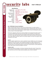
2.2.1 4U (20-Bay) / 3U (16-Bay) Models
1 2 3 4 5 6 7 8 9
10
11
Figure 2-5
No. LED Description
1 Power LED The LED shines when the power is on.
2 HDD Activity LED The LED shines when the HDDs are writing or reading data.
3 RAID status LED
The LED shines when any HDD among a created RAID set
is powered.
4 Failure Alert LED
The LED shines when damages occur to any HDD in the
RAID set.
5 HDD Group C LED The LED does not have any function.
6 HDD Group D LED The LED does not have any function.
7 System Alert LED
The LED shines and the system sounds on if one fan
stops or the GV-Hot Swap Surveillance System V5 is
overheated.
8 Alert LED (reserved)
9 Alarm Mute Button
Press this button to silence the alarm when the System
Alert LED shines and the system sounds.
10 HDD Power LED (White) The LED shines white after the HDD is installed.
11 HDD Activity LED (Blue) The LED shines blue if the HDD is reading or writing data.
Note: The HDD Activity LED (No.11) only shines if the installed HDD is SATA II.

12
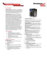
2.2.2 3U (8-Bay) Models
1 2 3 4 5
6
7
Figure 2-6
No. LED Description
1 Power LED The LED shines when the power is on.
2 HDD Activity LED The LED shines when the HDDs are writing or reading data.
3 RAID Status 1 ~ 8 LEDs The LEDs of HDD 1 ~ 8 shine when the HDDs are powered.
4 System Alert LED
The LED shines and the system sounds on if one fan
stops or the GV-Hot Swap Surveillance System V5 is
overheated.
5 Alarm Mute Button
Press this button to silence the alarm when the System
Alert LED shines and the system sounds.
6 HDD Power LED (White) The LED shines white after the HDD is installed.
7 HDD Activity LED (Blue) The LED shines blue if the HDD is reading or writing data.
Note: The HDD Activity LED (No.7) only shines if the installed HDD is SATA II.
Page is loading ...
Page is loading ...
Page is loading ...
Page is loading ...
Page is loading ...
Page is loading ...
Page is loading ...
Page is loading ...
Page is loading ...
Page is loading ...
Page is loading ...
Page is loading ...
Page is loading ...
Page is loading ...
Page is loading ...
Page is loading ...
Page is loading ...
Page is loading ...
Page is loading ...
Page is loading ...
Page is loading ...
Page is loading ...
Page is loading ...
Page is loading ...
Page is loading ...
Page is loading ...
Page is loading ...
Page is loading ...
Page is loading ...
Page is loading ...
Page is loading ...
Page is loading ...
Page is loading ...
Page is loading ...
Page is loading ...
Page is loading ...
Page is loading ...
Page is loading ...
Page is loading ...
Page is loading ...
Page is loading ...
Page is loading ...
Page is loading ...
Page is loading ...
Page is loading ...
Page is loading ...
Page is loading ...
Page is loading ...
Page is loading ...
Page is loading ...
Page is loading ...
Page is loading ...
Page is loading ...
Page is loading ...
Page is loading ...
Page is loading ...
Page is loading ...
Page is loading ...
Page is loading ...
Page is loading ...
-
 1
1
-
 2
2
-
 3
3
-
 4
4
-
 5
5
-
 6
6
-
 7
7
-
 8
8
-
 9
9
-
 10
10
-
 11
11
-
 12
12
-
 13
13
-
 14
14
-
 15
15
-
 16
16
-
 17
17
-
 18
18
-
 19
19
-
 20
20
-
 21
21
-
 22
22
-
 23
23
-
 24
24
-
 25
25
-
 26
26
-
 27
27
-
 28
28
-
 29
29
-
 30
30
-
 31
31
-
 32
32
-
 33
33
-
 34
34
-
 35
35
-
 36
36
-
 37
37
-
 38
38
-
 39
39
-
 40
40
-
 41
41
-
 42
42
-
 43
43
-
 44
44
-
 45
45
-
 46
46
-
 47
47
-
 48
48
-
 49
49
-
 50
50
-
 51
51
-
 52
52
-
 53
53
-
 54
54
-
 55
55
-
 56
56
-
 57
57
-
 58
58
-
 59
59
-
 60
60
-
 61
61
-
 62
62
-
 63
63
-
 64
64
-
 65
65
-
 66
66
-
 67
67
-
 68
68
-
 69
69
-
 70
70
-
 71
71
-
 72
72
-
 73
73
-
 74
74
-
 75
75
-
 76
76
-
 77
77
-
 78
78
-
 79
79
-
 80
80


Geovision GV-Hot Swap VMS System User manual
- Type
- User manual
- This manual is also suitable for
Ask a question and I''ll find the answer in the document
Finding information in a document is now easier with AI
Related papers
-
Geovision GV-Hot Swap System V5 User manual
-
-
-
-
-
-
-
-
-
Other documents
-
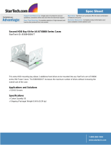 StarTech.com 8300HDDKIT Datasheet
-
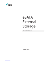 IDIS eSATA External Operating instructions
-
advidia A-35 Installation guide
-
ALIBI ALI-NVR71128R Setup Manual
-
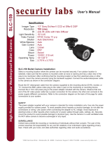 Security Labs SLC-159 User manual
-
 Security Labs SLC-1056 User manual
-
Lenovo 70BC9000EA_2WR Datasheet
-
i3 International SBB41 Installation guide
-
 Arcus 300 User manual
-
QNAP SS-839 PRO User manual


