Copyright © 2016 Ruckus Wireless, Inc. Page 1 of 4
Published August 2016, Part Number 800-71221-001 Rev B
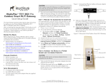
Unleashed R710 Access Point
Quick Setup Guide
This Quick Setup Guide provides step-by-step instructions on how to set up your Ruckus
Wireless Unleashed R710 Dual Band 802.11ac WiFi Access Point. After completing the
steps described in this Guide, the Unleashed Master Access Point (Master AP) will be
created. Additional Unleashed access points can be added to the network for additional
coverage and capacity.
Figure 1. Ruckus Wireless Unleashed R710 Access Point
Before You Begin
Before deploying Ruckus Wireless products, please check for the latest software and
release documentation.
• User Guides and Release Notes are available at
http://support.ruckuswireless.com/documents
• Product Limited Warranty documents are available at
http://support.ruckuswireless.com/warranty
• Online Training Resources are available at
https://training.ruckuswireless.com
Package Contents
• Unleashed R710 Access Point
• One T-bar mounting assembly kit, including:
• One T-bar bracket (2 separate plastic parts)
• Two each 1.0" L x No. 8 steel Phillips panhead mounting screws and plastic
wall anchors
• Regulatory flyer
• Product warranty statement
• Declaration of Conformity, if required
•This Quick Setup Guide
CONFIGURING THE AP
Continue with the following steps:
• Step 1: Collect Tools and Setup Requirements
• Step 2: Connect the AP to Power and Your Network
• Step 3: Log In and Run the Setup Wizard
• Step 4: Customize Your Wireless LANs
• Step 5: Deploy Additional Unleashed Access Points
Step 1: Collect Tools and Setup Requirements
• A computer running Windows 7 (procedures for other operating systems are similar).
• One Cat 5e (or better) Ethernet cable.
• A Ruckus Wireless 12VDC 902-1169-xx00 AC power adapter (sold separately)
--OR--
an 802.3at-compliant Power over Ethernet (PoE) switch or PoE injector.
--OR--
an 802.3af-compliant PoE switch or PoE injector.
• NOTE: The AP can operate off of 802.3af power, but the feature set is reduced:
the USB port is disabled, the second (eth1) Ethernet port is disabled, and the 2.4 GHz
transmit power is reduced from 28dBm to 25dBm (aggregate of spatial streams),
and country limits apply.
Optional hardware and tools:
• Customer-supplied small padlock with a 3.5mm (0.14”) or smaller shackle diameter,
used to fasten the AP to the secure mounting bracket or the T-bar bracket.
• Customer-ordered Ruckus Wireless 902-0120-0000 secure mounting bracket kit:
• If you are mounting the AP on a flat surface using the secure mounting bracket
kit, then you need an electric drill with 4.75mm (3/16”) drill bits.
• If you are mounting the AP on a pipe or pole using the secure mounting bracket
kit, then you will also need a 38.1mm to 63.5mm (1.5" to 2.5") pipe or pole,
two included stainless steel clamps, and hand tools to tighten the clamps.
Continue with Step 2: Connect the AP to Power and Your Network.
Step 2: Connect the AP to Power and Your Network
A After removing your Unleashed AP from its package, connect it to your network
switch or router using an Ethernet cable.
B Using an AC adapter (sold separately), connect the AP 12VDC port to a protected
power source (B in Figure 2).
Alternatively, connect the 10/100/1000 POE In port to a PoE injector or switch for
both power and network connectivity (A in Figure 2).
Figure 2. AP ports
C Verify that the PWR LED on the AP is a steady green.
Continue with Step 3: Log In and Run the Setup Wizard.
Step 3: Log In and Run the Setup Wizard
A As soon as the Unleashed AP is powered on and connected to the local network, it
boots up and begins broadcasting a temporary unencrypted WLAN named
“Configure.Me-[xxxxxx]” from the 2.4 GHz radio only.
B Using your client’s WiFi configuration settings, select and associate to the
“Configure.Me-[xxxxxx]” WLAN.
C Launch a web browser and enter the following into the browser’s URL bar:
unleashed.ruckuswireless.com, and press Enter.
Figure 3. Connect to the “ConfigureMe” WLAN
\
Figure 4. : Select Create New Unleashed Network
D Select Create New Unleashed Network, and click Start to begin.
E The “Configuring Unleashed Master” progress screen displays the progress. Wait
until the initialization process completes.
.
F Once initialization is complete, ensure that you are still connected to the
“Configure.Me” WLAN, and click Next.
G You will be redirected to the Setup Wizard. Complete the steps in the Setup Wizard
and click Finish.
Note: The PoE switch port must run link layer discovery protocol (LLDP) power over
Ethernet/MDI (PoE+) in order for the Unleashed R710 to operate in full-power mode.
This may require enabling both LLDP and Power via MDI (dot3) on the switch, if
available.
Note: The AP can use link aggregation control protocol (LACP) to bond the two
physical Ethernet ports together to form a single logical channel. Refer to the
Configuring Link Aggregation (LACP) Using CLI section in the Indoor AP User Guide.
Note: Do NOT disconnect the power or network cable from the device during the
setup process.