Aiphone IS User manual

Type
User manual

This manual is also suitable for

Thank you for selecting Aiphone for your communication and security needs. Please read this manual and the separate
“OPERATION MANUAL” carefully before setting and using this system.
Refer to the provided “INSTALLATION MANUAL” for complete information regarding this system.
*
IMPORTANT
Please read and understand the system setting procedures before beginning the setup process.
Please note that images and illustrations depicted in this manual may differ from the actual ones.
IS SERIES
Commercial & Security IP Video Intercom system
Standard (IP) System
SETTING MANUAL
834174 B 0811YZ
2
CONTENTS
ABOUT THIS MANUAL ............... 4
PURPOSE OF THE SYSTEM
SETTINGS ................................... 4
SETTING LIST ............................. 5
SYSTEM SETTING FLOW .........11
Flow 1 ........................................... 12
Flow 2 ........................................... 13
Flow 3 ........................................... 14
Remote site connection
settings ........................................ 15
STARTING UP THE SYSTEM
AND PREPARING FOR THE
SETTINGS ................................. 16
System requirements for PC ..... 16
Starting up the system ............... 16
THE SYSTEM SETTING
DETAILS .................................... 18
The basic setting procedure ...... 18
Making network settings to
each IP unit [Network setting:
Individual] .................................... 19
Making network settings for
the whole system
[Network setting: Common] ....... 19
Setting the administrator ID and
password [Administrator
setting] ......................................... 20
Con rming the IP units
connected to the system
[IP unit search] ............................ 20
Registering areas and remote
sites [System setting – Area/Site
registration] (Required) .............. 21
Registering zones [System
setting – Zone registration] ...... 21
Registering IP units [System
setting – IP unit registration] ..... 22
Registering control units
[System setting – Control
units composition] ...................... 22
Registering stations and PA
outputs [System setting –
Registering stations] .................. 23
Making detailed settings to
stations and control units
[System setting – Advanced
station settings] .......................... 24
Basic setting procedure ..........................24
Making detailed settings to door
stations or room sub stations ................24
Making detailed settings to master
stations ..................................................25
Making detailed settings to the central
control unit(s), add-on control unit(s) or
room sub control unit(s) ........................26
Registering stations and PA
outputs to zones [System
setting – Zone setting] ............... 27
Registering sound sequences
[Chime setting – Registering
sound sequences] ...................... 27
Registering daily chime
schedule [Chime setting –
Registering daily chime
schedule] ..................................... 28
Setting chime schedule
[Chime setting – Chime
schedule setting] ........................ 28
Registering daily transfer
schedule [Transfer setting –
Registering daily transfer
schedule] ..................................... 29
Setting transfer schedule
[Transfer setting – Transfer
schedule setting] ........................ 30
Setting the timer
[Timer setting]
............................. 31
3
Setting stations to receive
calls and zones to receive
(chime) paging from remote
sites [Remote site pilot call
setting] ......................................... 31
Telephone setting (North
America only) .............................. 33
Video setting ............................... 34
Setting time and date
[Time and date setting] .............. 34
E-mail setting .............................. 35
Downloading/uploading setting
data [Setting le] ......................... 35
When downloading setting data
onto the PC ........................................35
When uploading setting data ..............35
Updating the system
[Updating the system] ................ 35
Registering sound les for
chime sources on the central
control unit (IS-CCU) .................. 36
MAINTENANCE ......................... 37
Initializing the system
[Initialization] ............................... 37
Downloading system log
[System log] ................................ 37
Updating the rmware
[Firmware update] ....................... 37
Downloading updated rmware
data ....................................................37
Referring to the troubleshooting
guide [Troubleshooting] ............. 37
Registering your system
[Registration] ............................. 37
Setting Information Memo ....... 38
4
ABOUT THIS MANUAL
The IS system provides various manuals to meet various system planning and work processes. Use the manuals necessary for your
system.
Manual con gurations
The following manuals are provided for a standard (IP) system. Read all the manuals for installing, setting up, and using a standard (IP)
system, or provide the manuals to the persons working with the system.
INSTALLATION MANUAL (A booklet included with the central control unit (IS-CCU))
Used for installing and connecting control units, stations and power supply unit. (For an installer or serviceman)
INSTALLATION MANUAL (A booklet included with the IP master station (IS-IPMV))
Used for installing and connecting IP master stations and IP video door stations (mainly for a network direct system). (For
an installer or serviceman)
SETTING MANUAL (This manual on the CD-ROM included with the IP control unit (IS-IPC))
This manual describes how to make the system settings and system maintenance. (For an installer or serviceman)
OPERATION MANUAL (An electronic manual on the CD-ROM included with the IP control unit (IS-IPC))
Information for using the system for calling, communicating, paging, monitoring, etc. (For users of the system)
PURPOSE OF THE SYSTEM SETTINGS
Con gure the system settings based on how your system is planned to be used. System settings must be completed before the
system will operate.
CAUTION:
Make the settings correctly. If the settings are not made correctly, the system will not function as planned.
5
GETTING STARTED USING THE SYSTEM APPENDIX
SETTING THE SYSTEM
SETTING LIST
The following is the list of system settings you can make via the web browser. The titles or items in shaded cells are required.
NOTES:
The following list is a brief overview of the setting items available in the system settings on a PC. The descriptions, and the style and order of
descriptions do not necessarily equate with the actual displays.
Make a note of the setting results you have made by using the “Setting Information Memo” (
P. 38) etc. in case of unexpected data erasure, and
keep it in a safe place not to lose it.
Title Sub title Item Sub item Setting range Default
- - (Language) - English/French/German/Spanish/Dutch/
Italian/Japanese
English
Network setting Network setting:
Individual
IP version - IPv4 IPv4
Host unit setting - Host unit/Client unit Client unit
Host unit IP address (available
when [Host unit setting] is set to
“Client unit”)
(Enter the Host unit IP address.) -
System name
(available when [Host
unit setting] is set to
“Host unit”)
- Up to 24 alphanumeric characters -
(Select the network
setting method.)
- DHCP/Static IP Address DHCP
Static IP Address Static IP Address (required when
[Static IP Address] is selected)
0 – 255 (for each eld) 192.168.0.40
Subnet Mask (required when
[Static IP Address] is selected)
0 – 255 (for each eld) 255.255.255.0
Default Gateway 0 – 255 (for each eld) -
Primary DNS Server 0 – 255 (for each eld) -
Secondary DNS Server 0 – 255 (for each eld) -
MAC address - (Unmodi able) (Unmodi able)
Unit name - Up to 24 alphanumeric characters
(except accent marks, umlaut marks,
etc.)
-
Web port - (Unmodi able) (Unmodi able)
Connection port - 1024 - 65535 5060
Connection
Password
- Up to 16 alphanumeric characters aiphone
Network setting:
Common
UPnP - ON/OFF ON
Global IP address
(available when
[UPnP] is set OFF)
- 0 - 255 (for each eld) -
Connection port:
global
- (Unmodi able) (Unmodi able)
Multicast address
1 - 5
- 239.0.0.0 - 239.255.255.255 1: 239.0.1.1
2: 239.0.1.2
3: 239.0.1.3
4: 239.0.1.4
5: 239.0.1.5
Audio/video port - 1024 - 65535 50800 - 50813
Administrator
setting
- New administrator ID - Up to 16 alphanumeric characters -
Current Password - Up to 16 alphanumeric characters - (aiphone)
New Password - Up to 16 alphanumeric characters -
New Password
(Re-type)
- Up to 16 alphanumeric characters -
IP unit search - - - - -
6
Title Sub title Item Sub item Setting range Default
System setting Area/Site
registration
Area/Site Name - Up to 24 alphanumeric characters (for
up to 99 areas including sites)
* Up to 31 for sites
1 (for Area
number 01)
Area/Site - Area/Site Area
IP Address (sites
only)
- 0 - 255 (for each eld) -
Port number (sites
only)
- 1024 - 65535 -
Connection
Password (sites only)
- Up to 16 alphanumeric characters -
Door release (sites
only)
- ON/OFF ON
Zone registration Zone name - Up to 24 alphanumeric characters (for
up to 99 zones)
-
IP unit registration Station type - IP control unit, IP video door station, IP
master station, PC master station
-
MAC address - - -
Unit name - Up to 24 alphanumeric characters -
Port number - 1024 - 65535 IP control unit:
50900 - 50906
IP station:
50900 - 50902
Control units
composition
(Depends on
the system
con guration.)
- Connected/Not connected Not connected
Registering
stations
Area (stations only) - (Area) 01 to 99 (Area) 01
Station number
(stations only)
- 001 to 999
0001 to 9999
00001 to 99999
-
Station name
(for stations)
- Up to 24 alphanumeric characters -
Station name
(for PA output)
(Required when
an external unit is
connected to the
corresponding PA
output terminals)
- Up to 24 alphanumeric characters -
Station type
(sub stations only)
- (Select from the registered ones.) (Depends on
the control
unit.)
Advanced station
settings
Video door
station/Audio
door station/
Room sub
station
Called
stations
Call priority Normal/Priority/Urgent Normal
Called stations (Set up to 20 targets from the registered
ones.)
-
Contact input
(room sub
stations only)
Contact type Normally open (NO)
/Normally closed (NC)
Normally open
(NO)
Call priority/Answering
the page
Answering the page
/Call (Normal/Priority/Urgent)
Normal
Other
Transmit volume boost
at PTT
ON/OFF
(ON: approx. +6dB up)
OFF
Camera zoom image
preset (video door
stations only)
0 (wide)/1/2/3/4/5/6/7/8/9 (zoom) 5 (Center)
Call acknowledge tone
on/off
ON/OFF ON
Backlight adjustment
(video door stations
only)
Exposure +/Exposure - Exposure +
Speaker
(room sub stations
only)
Built-in speaker
/External speaker
Built-in
speaker
7
GETTING STARTED USING THE SYSTEM APPENDIX
SETTING THE SYSTEM
Title Sub title Item Sub item Setting range Default
System setting Advanced station
settings
Master station Stations to be scan monitored (Select up to 20 sub stations from the
registered ones.)
-
Other
Master station function:
paging, chime, monitor,
door release, and
remote site call
ON/OFF ON
Central
control unit
Contact input
(Contact input) S1 to S4 S1
Contact type
Normally open (NO)
/Normally closed (NC)
Normally open
(NO)
Trigger condition None/Broadcast chime/Stop chime None
Sound source
(Only when "Broadcast
chime" is selected at
"Trigger condition")
Internal sound source (Select a
sound le or sequence name from the
registered ones in the list.)
/External sound source (Select either
External sound source 1 or 2.)
-
Chime priority
(Only when "Broadcast
chime" is selected for
"Trigger condition")
Normal/Priority/Urgent Normal
Zone name
(Only when "Broadcast
chime" is selected at
"Trigger condition")
(Select from the registered ones.) -
Contact output
(Contact output
terminal)
L1 to L8 L1
Contact type
Normally open (NO)
/Normally closed (NC)
Normally open
(NO)
Trigger condition None/Calling notice/Door release
/External sound source/PA output
None
Calling notice
(Only when "Calling
notice" is selected at
"Trigger condition")
Normal: OFF/ON
Priority: OFF/ON
Urgent: OFF/ON
Normal: OFF
Priority: OFF
Urgent: OFF
Door release
(Only when "Door
release" is selected at
"Trigger condition")
(Select from the sub stations registered
and set for the central control unit.)
-
External sound source
(Only when "External
sound source" is
selected at "Trigger
condition")
External sound source 1
/External sound source 2
-
PA output
(Only when "PA output"
is selected at "Trigger
condition")
PA output 1 to 4 -
Room sub
control unit/
Add-on
control unit
Contact output
(Contact output
terminal)
L1 to L4 L1
Contact type
Normally open (NO)/Normally closed (NC)
Normally open
(NO)
Trigger condition None/Calling notice/Door release/PA
output
None
Calling notice
(Only when "Calling
notice" is selected at
"Trigger condition")
Normal: OFF/ON
Priority: OFF/ON
Urgent: OFF/ON
Normal: OFF
Priority: OFF
Urgent: OFF
Door release
(Only when "Door
release" is selected at
"Trigger condition")
(Select from the sub stations registered
and set for each control unit.)
-
PA output
(Only when "PA output"
is selected at "Trigger
condition")
PA output 1 to 4 -
Zone setting Zone number - (Select from the registered ones.) -
Stations - (Select from the list.) -
PA output - (Select from the list.) -
8
Title Sub title Item Sub item Setting range Default
Chime setting*
1
Registering sound
sequences
Sound sequence
number
- SS1 to SS20 SS1
Sound sequence
name
- Up to 24 alphanumeric characters -
Step - 1 to 10 1
Sound source Sound le (Select from the registered ones.) -
Repeat times 1 to 10 1
Registering daily
chime schedule
Schedule number - DS1 to DS10 DS1
Schedule name - Up to 24 alphanumeric characters -
Chime time - Hour: 0 to 23
Minute: 0 to 59
Second: 0 to 59
-
Sound source - Sound le (Select from the registered
ones.)
/Sound sequence (Select from the
registered ones.)
/External sound source (1 or 2)
-
Zone number - (Select from the registered ones.) -
Chime priority - Normal/Priority/Urgent Normal
Chime schedule
setting
Weekly schedule (Repeat setting) Every week/Every other week Every week
Schedule start date From the current day to 1 year ahead -
Schedule end date From the start day to 1 year ahead -
(Chime schedule) None/DS1 to DS10 (for each day of the
week)
None
Individual schedule (Date) From the current day to 1 year ahead -
Daily chime schedule (Select from the registered ones.) None
Chime time Hour: 0 to 23
Minute: 0 to 59
Second: 0 to 59
-
Sound source Sound le (Select from the registered
ones.)
/Sound sequence (Select from the
registered ones.)
/External sound source (1 or 2)
-
Zone number (Select from the registered ones.) -
Chime priority Normal/Priority/Urgent Normal
Schedule download - (Download the chime (and transfer)
schedule data in CSV format.)
-
Transfer setting Registering daily
transfer schedule
Schedule number - DT1/DT2 DT1
Schedule name - Up to 24 alphanumeric characters -
Call transfer time - Hour: 0 to 23
Minute: 0 to 59
(Set to the Start time and End time
individually.)
-
Transfer schedule
setting
Weekly schedule (Repeat setting) Every week/Every other week Every week
Schedule start date From the current day to 1 year ahead -
Schedule end date From the start day to 1 year ahead -
(Transfer schedule) None/DT1/DT2 (for each day of the
week)
None
Individual schedule (Date) From the current day to 1 year ahead -
Daily transfer schedule (Select from the registered ones.) None
Call transfer time Hour: 0 to 23
Minute: 0 to 59
(Set to the Start time and End time
individually.)
-
Timer setting - Call Normal/Priority/Urgent 10 to 600 (sec.), 0 (Unlimited)
Normal: 30 (sec.)
Priority: 90 (sec.)
Urgent: 0
(Unlimited)
Communication In Local 30 to 600 (sec.) 60 (sec.)
Via IP 30 to 600 (sec.) 60 (sec.)
Telephone (North America only) 30 to 600 (sec.) 120 (sec.)
Paging - 30 to 600 (sec.) 60 (sec.)
Monitor - 10 to 600 (sec.) 60 (sec.)
*
1
: It is required that you have registered sound source(s) on the IS-CCU connected to the IS-IPC (as the IP host unit) directly.
9
GETTING STARTED USING THE SYSTEM APPENDIX
SETTING THE SYSTEM
Title Sub title Item Sub item Setting range Default
Timer setting - Scan monitor:
Switching
- 5 to 60 (sec.) 7 (sec.)
Contact output External sound source 1 10 to 300 (sec.) 30 (sec.)
External sound source 2 10 to 300 (sec.) 30 (sec.)
Door release - 0 to 300 (sec.), (0: Released while
holding the Door release button
pressed.)
10 (sec.)
Remote site
pilot call setting
- Remote site master
call
Normal/Priority/Urgent (Select one from the registered stations
in your site for each of “Normal”, “Priority”
and “Urgent”.)
-
Remote site door call Normal/Priority/Urgent (Select up to 20 stations from the
registered master stations in your site for
each of “Normal”, “Priority” and “Urgent”.)
-
Remote site room
sub call
Normal/Priority/Urgent (Select up to 20 stations from the
registered master stations in your site for
each of “Normal”, “Priority” and “Urgent”.)
-
Remote site paging Normal/Priority/Urgent/
Broadcast
(Select one from the registered zones in
your site for each of “Normal”, “Priority”,
“Urgent” and “Broadcast”.)
-
Remote site chime Zone name (Select one from the registered zones in
your site for each of “Normal”, “Priority”
and “Urgent”.)
-
Sound le name/sequence name Sound le: SF1 - SF15
Sound sequence: SS1 - SS20
-
Telephone
setting (North
America only)
- Telephone
connection
- ON/OFF OFF
Called telephone
number
1/2/3 (1 to 30 digit number can be set for each
by using “0 - 9”, “,” and “
_
”.)
-
Call change time - 10 – 60 (sec.) 30 (sec.)
Telephone pass code - 3 to 4 digit number 0000
Dial pause duration - 1 to 10 (sec.) 1 (sec.)
DTMF duration - 50 to 300 (msec.) 80 (msec.)
Waiting time for ring-
back-tone
- 1 to 30 (sec.) 15 (sec.)
Telephone pass code
input time
- 3 – 15 (sec.) 3 (sec.)
Dial-tone detecting
time
- 1 – 15 (sec.) 5 (sec.)
Sound detection
waiting time
- 500 – 1500 (msec.) 500 (msec.)
Sound detection time - 300 – 1000 (msec.) 300 (msec.)
Call detection time - 100 – 1000 (msec.) 200 (msec.)
Detection setting
Outgoing
call tone
detection
Dial-tone detection
ON/OFF ON
Outgoing call tone
detection priority
Normal/Priority Normal
Called party
answer
detection
Shorter ring-back-tone
than previous one
ON/OFF ON
Ring-back-tone detection time:
0.5 - 10.5 (sec.)
0.5 (sec.)
End of ring-back-tone
ON/OFF ON
Waiting time for ring-back-tone:
0.5 - 10.5 (sec.)
5.5 (sec.)
Called party hang-
up detection
Busy tone detection ON/OFF ON
Dial tone detection ON/OFF ON
CPC signal detection
ON/OFF ON
CPC signal detection time:
50 - 1000 (msec.)
250 (msec.)
Reverse polarity
detection
ON/OFF ON
Video setting - Frame Rate - 1/2/5/7.5/10/15 (fps) 15 (fps)
Quality - Low, Middle, High, Excellent Excellent
10
Title Sub title Item Sub item Setting range Default
Time and date
setting
- Set current time Manual setting Year: 2009 to 2099
Month: 1 to 12
Day: 1 to 31
Hour: 0 to 23
Minute: 0 to 59
Second: 0 to 59
(Internal time
of the IP Host
unit)
Synchronized with PC - -
NTP Synchronized with NTP server ON/OFF OFF
NTP server*
1
IP address or domain name -
NTP port number*
1
1 to 65535 123
(UTC time zone*
1
)
Hour difference*
1
-12 to +13 (h) 0
(UTC time zone*
1
)
Minute difference*
1
-45/-30/0/+30/+45 (m) 0
Synchronize interval 1 to 240 (h) 24 (h)
Daylight savings time - ON/OFF OFF
Starts*
2
Month JAN to DEC (M) JAN
Day (Week) 1st to 4th (W)/The last 1st
(Day) Sunday to Saturday Sunday
Hour (Hour) 0 to 23 (h) -
(Minute) 0 to 59 (m) -
Ends*
2
Month JAN to DEC (M) JAN
Day (Week) 1st to 4th (W)/The last 1st
(Day) Sunday to Saturday Sunday
Hour (Hour) 0 to 23 (h) -
(Minute) 0 to 59 (m) -
Hour difference*
2
0 to 12 (h) 1
Minute difference*
2
0/30/45 (m) 0
E-mail setting
- Email destination
address
1/2/3 Up to 256 alphanumeric characters -
Email source
address
- Up to 256 alphanumeric characters -
SMTP authentication SMTP server Up to 256 alphanumeric characters -
SMTP server port 1 to 65535 465
(Email) login ID Up to 256 alphanumeric characters -
Password Up to 64 alphanumeric characters -
Mailing event Call: Normal ON/OFF OFF
Call: Priority ON/OFF OFF
Call: Urgent ON/OFF OFF
System start ON/OFF OFF
Data communication error in the
system
ON/OFF OFF
Setting le
Downloading
setting data
-
-- -
Uploading setting
data
-
-- -
*
1
: Available only when [Synchronized with NTP server] is set to ON.
*
2
: Available only when [Daylight savings time] is set to ON.
11
GETTING STARTED USING THE SYSTEM APPENDIX
SETTING THE SYSTEM
SYSTEM SETTING FLOW
First of all, make the network settings. The network setting method differs according to the network environment. Select the ow
suitable for your network environment from the chart below, and start the network settings after you fully understand it. After the
network settings are nished, make the other individual system settings. See P. 18-36 for the system setting details.
NOTE:
The system settings should be made mainly on the IP host unit in the system (in a site). You select one as the IP host unit among the IP units
connected to the system and others as the IP client units. (A PC master station (IS-SOFT) cannot be used as the IP host unit.)
First select the
Flow 1
,
Flow 2
or
Flow 3
from the chart below, then start the network settings by
following the selected ow.
Do you have a DHCP server (or router that
has a DHCP server function) in the network,
and does it have an automatic IP address-
assigning function?
If you communicate with remote sites (calling, call transferring, paging, etc.), make the remote site connection settings (P. 15)
after the network settings for your site have nished.
Flow 1
(IP host unit: A static IP address is set,
IP client units: IP addresses are assigned by the DHCP
server automatically)
Flow 2
(All units: Static IP addresses are set)
YES
YES
(*3)
YES NO
YES
NO
NO
(*4)
NO
(*3)
Go to P. 12.
Go to P. 13.
NOTE:
If you connect a PC master station (IS-SOFT) to the network, install the software (IS-SOFT) to a PC before connecting it to the network.
(*1): UPnP may not function normally depending on the router. Refer to [System log][UPnP operation check result] (P. 37) on the
IP host unit. If the [System log] window shows that UPnP is not functioning normally, the UPnP function of the router cannot be
used with this system. In that case, set [UPnP] to OFF at [Network setting: Common] (P. 19) and then make settings on the
router again by con rming the settings at [IP unit registration] (P. 22). See http://www.aiphone.net/ for the router to which the
operartion check has nished and setting examples.
(*2): If the DHCP server (or router that has a DHCP server function) has a function to assign a static IP address to a speci ed MAC
address, you can make the DHCP server assign the IP addresses to all the IP units automatically.
(
Flow 3
(All units: IP addresses are assigned by the DHCP server automatically) (P. 14))
(*3): Set [UPnP] to ON at [Network setting: Common] (P. 19) (Default: ON).
(*4): Set [UPnP] to OFF at [Network setting: Common] (P. 19) (Default: ON).
START
Do you use a router on which UPnP functions,
and does UPnP function normally?
Do you have a DHCP server (or router that
has a DHCP server function) in the network,
and does it have an automatic IP address-
assigning function?
Do you communicate with remote sites (calling, call transferring,
paging, etc.)?
(*2)
(*1)
12
Flow 1
(IP host unit: A static IP address is set,
IP client units: IP addresses are assigned by the DHCP server automatically)
Search for the IP address of the IP host unit from the MAC
address of the IP host unit by using IS_IPSEARCH.exe (in
the CD-ROM included with the IP control unit (IS-IPC)). (If the
address does not appear, repeat this step until it appears.)
Then access the address from the browser on the PC. (P. 17)
This address is the temporary one for the initial setting.
*
Connect the units and the PC used for settings to the
network, and then turn them on.
(IP addresses are assigned to the IP client units by the
DHCP server automatically.)
If you will connect your site with remote sites, make the
remote site connection settings. ( P. 15)
Make the other system settings. ( P. 20-36)
Connect the units and the PC used for settings to the
network, and then turn them on.
Make the [Network setting: Individual] settings on the IP
host unit. ( P. 19)
Set it as "Host unit".
*
Set the static IP address to the IP host unit.
*
Add IP units you will use in the system at [IP unit
registration] on the IP host unit. ( P. 22)
Make the [Network setting: Individual] settings on the IP
host unit. ( P. 19)
Set it as "Host unit".
*
Set the static IP address to the IP host unit.
*
Make the [Network setting: Individual] settings on the IP
client units. ( P. 19)
Set them as "Client unit" (if they are not set as "Client unit").
*
Enter the IP address of the IP host unit.
*
Select "DHCP" for acquiring IP addresses (if "DHCP" is not selected).
*
Search for the IP units (other than PC master stations) you
will use in the system at [IP unit search] on the IP host unit,
and open the setting window for each IP unit. ( P. 20)
Con rm the [Network setting: Common] settings on the IP
host unit. ( P. 19)
Con rm that the multicast addresses and/or port numbers do not overlap those
*
of other manufacturers network devices connected to the same network.
Update the system at [Updating the system]. ( P. 35)
(When making the IP host unit settings
before connecting the units to the network)
(Log in.)
(Log in.)
(When making the IP host unit settings
after connecting the units to the network)
: Settings on the IP host unit
: Settings on the IP client units
START
Write down the MAC addresses of all the IP units to be used
in the system in advance by using the “Setting Information
Memo” (P. 38) etc.
The MAC address is labeled on each unit.
*
Decide the static IP address for the IP unit to be used as the
IP host unit.
Use an address out of the range of DHCP assignment for the IP host
*
unit in order to prevent the address for the IP host unit being assigned
to another IP client unit by an in uence of the turn-on order between
the IP host unit and the router (that has a DHCP server function) etc.
* This is the outline of setting ow. Also make the detailed settings on each setting window referring to the corresponding pages.
Connect the IP host unit and the PC used for settings
directly, and then turn them on. After a while, access
"https://192.168.0.40/" from the browser on the PC. (P. 17)
NOTES:
When connecting a PC to the IP unit directly, use an Ethernet
crossover cable.
If a warning dialog box for security or guarding against virus
programs appears when accessing the web browser, give permission.
13
GETTING STARTED USING THE SYSTEM APPENDIX
SETTING THE SYSTEM
Flow 2
(All units: Static IP addresses are set)
Write down the MAC addresses of all the IP units to be
used in the system in advance by using the “Setting
Information Memo” (P. 38) etc.
The MAC address is labeled on each unit.
*
Decide the static IP address for each IP unit.
Make the [Network setting: Individual] settings on each
IP unit individually. ( P. 19)
: Settings on the IP host unit
: Settings on the IP client units
START
Connect the units and the PC used for settings to the
network, and then turn them on respectively.
Add IP units you will use in the system at [IP unit
registration] on the IP host unit. ( P. 22)
(The selected unit is added in the list whenever selected.)
Con rm the [Network setting: Common] settings on the
IP host unit. ( P. 19)
Con rm that the multicast addresses and/or port
*
numbers do not overlap those of other manufacturers
network devices connected to the same network.
For the IP host unit
For each IP client unit
If you will connect your site with remote sites, make the
remote site connection settings. ( P. 15)
Make the other system settings. ( P. 20-36)
Connect the IP host unit and the PC used for settings
directly, and then turn them on. After a while, access
"https://192.168.0.40/" from the browser on the PC.
(P. 17)
NOTES:
When connecting a PC to the IP unit directly, use an
Ethernet crossover cable.
If a warning dialog box for security or guarding against virus
programs appears when accessing the web browser, give permission.
Connect an IP client unit and the PC used for settings
directly, and then turn them on. After a while, access
"https://192.168.0.40/" from the browser on the PC.
(P. 17)
NOTES:
When connecting a PC to the IP unit directly, use an
Ethernet crossover cable.
If a warning dialog box for security or guarding against virus
programs appears when accessing the web browser, give permission.
Make the [Network setting: Individual] settings on the
IP host unit. ( P. 19)
Set it as "Host unit".
*
Set the static IP address to the IP host unit.
*
Make the [Network setting: Individual] settings on the
IP client unit. ( P. 19)
Set it as "Client unit".
*
Enter the IP address of the IP host unit.
*
Set the static IP address to the IP client unit.
*
Update the system at [Updating the system]. ( P. 35)
(Log in.)
(Log in.)
* This is the outline of setting ow. Also make the detailed settings on each setting window referring to the corresponding pages.
14
Flow 3
(All units: IP addresses are assigned by the DHCP server automatically)
Write down the MAC addresses of all the IP units to be used
in the system in advance by using the “Setting Information
Memo” (P. 38) etc.
The MAC address is labeled on each unit.
*
Set the router (or DHCP server) so that it assigns a static IP
address to the IP unit to be used as the IP host unit.
: Settings on the IP host unit
: Settings on the IP client units
START
Connect the units and the PC used for settings to the
network, and then turn them on.
Access the IP address assigned to the IP host unit from the
browser on the PC. (P. 17)
Make the [Network setting: Individual] settings on the IP
host unit. ( P. 19)
Set it as "Host unit".
*
Select "DHCP" for acquiring an IP address.
*
Make the [Network setting: Individual] settings on the IP
client units respectively. ( P. 19)
Set them as "Client unit" (if they are not set as "Client unit").
*
Enter the IP address of the IP host unit.
*
Select "DHCP" for acquiring IP addresses (if "DHCP" is not
*
selected).
Update the system at [Updating the system]. ( P. 35)
Search for the IP units (other than PC master stations) you
will use in the system at [IP unit search] on the IP host unit,
and open the setting window for each IP unit. ( P. 20)
Add IP units you will use in the system at [IP unit
registration] on the IP host unit. ( P. 22)
Con rm the [Network setting: Common] settings on the IP
host unit. ( P. 19)
Con rm that the multicast addresses and/or port numbers
*
do not overlap those of other manufacturers network
devices connected to the same network.
If you will connect your site with remote sites, make the
remote site connection settings. ( P. 15)
Make the other system settings. ( P. 20-36)
(Log in.)
* This is the outline of setting ow. Also make the detailed settings on each setting window referring to the corresponding pages.
Update the system at [Updating the system]. ( P. 35)
15
GETTING STARTED USING THE SYSTEM APPENDIX
SETTING THE SYSTEM
Complete the network settings for your site by following
Flow 1
,
Flow 2
or
Flow 3
. (P. 12-14)
Get the following information for the remote sites you will
connect with your site.
"Global IP address"
"Connection port: global"
"Connection Password"
Set the following setting items on the IP host unit. ( P. 19)
[Network setting: Individual] :
"Default Gateway"
[Network setting: Common] :
"UPnP"
"Global IP address"
"Audio/video port"
Make the [Area/Site registration] on the IP host unit. ( P. 21)
* Select "Site" with the "Area/Site" pull-down menu and enter
the information of the site you will connect.
Open the [IP unit registration] window on the IP host unit,
and then click the
Port forwarding setting
button. ( P. 22)
Another window opens and the port forwarding setting
*
contents are displayed.
: Settings on the IP host unit
: Required when [UPnP] is set
to OFF at [Network setting:
Common] ( P. 19)
Procedure
Remote site connection settings
You need to make the remote site connection settings to enable communication between your site and remote sites. Make the settings
by following the procedure below after the network settings for your site have nished.
Update the system at [Updating the system]. ( P. 35)
Set the router with the port forwarding setting contents you
con rmed in the previous step.
* This is the outline of setting ow. Also make the detailed settings on each setting window referring to the corresponding pages.
16
STARTING UP THE SYSTEM AND PREPARING FOR THE SETTINGS
The system settings are mainly made on the PC by accessing the web browser for the settings incorporated with the IP control unit
(IS-IPC) as the IP host unit. It is recommended to use only one PC for the settings that is connected to the system.
System requirements for PC
Your PC and operating environment must meet the following system requirements to make the settings.
Network 10BASE-T Ethernet, 100BASE-TX Ethernet
Web browser Internet Explorer 6.0 or later (with Internet Options SSL 3.0 enabled)
Starting up the system
Connect a PC to the IP control unit.
1
[When connecting a PC to the IP control unit via
a hub (switch)]
RJ45
RJ45
RJ45
RJ45
NOTES:
Be sure to connect the CAT5e/6 cable to the LAN ports of both
units.
The IP address of IP control unit is set to (192.168.0.40) and
Subnet Mask is set to (255.255.255.0) as default. Change the
IP address of your PC if needed.
[When connecting a PC to the IP control unit
directly]
RJ45
RJ45
NOTES:
When connecting a PC to the IP control unit directly, use an
Ethernet crossover cable.
The IP address of IP control unit is set to (192.168.0.40) and
Subnet Mask is set to (255.255.255.0) as default. Change the
IP address of your PC if needed.
100m (330')
10BASE-T/
100BASE-TX
100m (330')
10BASE-T/
100BASE-TX
CAT5e/6
(Straight-through cable)
CAT5e/6
(Straight-through
cable)
Hub
(Switch)
PC
100m (330')
10BASE-T/100BASE-TX
CAT5e/6 (Crossover cable)
PC
(Continued on next page)
17
GETTING STARTED USING THE SYSTEM APPENDIX
SETTING THE SYSTEM
Press down the "I" side of POWER switch to turn on
2
the unit.
It may take long until the unit gets started.
*
Turn on all the units constituting the system depending
*
on the network setting method.
The status LED of an IP video door station changes from
*
red lighting to orange blinking.
(When the settings have correctly made, it changes to
orange lighting.)
The status LED of an IP master station changes from red
lighting to red blinking.
(When the settings have correctly made, it turns off.)
Start up the PC, and then open the browser window.
3
Enter the
4
(static) IP address assigned to the IP
control unit to access the web browser for settings.
Default: https://192.168.0.40
192.168.0.40/
After selecting
English
as the target language, the login
window of the web browser is displayed.
Log in to the system by setting the following items.
5
ID
Enter “aiphone”.
Password
Enter “aiphone”.
Login
Click
Login
to display the setting window.
When you log in for the rst time, the [
*
Registration]
window appears. Register your system as needed.
(When registering your system, if you use an IS-SOFT in
the system, enter the license key of the IS-SOFT.)
NOTE:
Be sure not to log in to the system more than once at the same
time by opening multiple browser windows on the PC.
Go to the next page.
Con rm that the following LEDs
*
operate as shown below.
POWER switch
Press down "I" side to turn on the
unit.
Press down "O" side to turn off the
unit.
Lights up.
Changes to blinking after lighting.
(When the system settings have
nished correctly, this LED turns from
blinking (initializing) to lighting.)
18
THE SYSTEM SETTING DETAILS
The basic setting procedure
When you have logged in to the system, the setting window appears. You can make the settings on this window.
Make sure to refer to the on-screen instructions and comments displayed on each window when you make the settings.
*
Depending on the PC and its OS or environment, the display may differ.
*
<Setting window example>
The setting procedure
Click a title in the table of contents on which you wish to make the settings.
1
The setting window of the title is displayed.
Make the settings on the setting items individually.
2
When you have nished making the settings on the current window, click
3
Temporarily stored
to save the setting
results temporarily.
If you wish to cancel the setting results you have made, click a title in the table of contents or “Refresh” in the web browser
*
menu. (If you change the current window to another without storing the setting results temporarily, a pop-up window appears
asking if you want to store the results temporarily or not.)
Repeat step
4
1 to 3 to make the settings on the other titles.
To log out of the system, click [
*
Logout] in the table of contents.
Setting contents display area
The setting items of the selected setting title and their
details are displayed here.
Table of contents
The setting titles are listed here.
Click the title on which you want
to make the settings to display the
corresponding setting window.
Instructions area
The instructions for settings are
displayed here.
Temporarily stored
Click this to save the current setting results
temporarily.
This temporary storing will not update the *
system with the new setting results. To update
the system, click the title “Updating the system”
and follow the necessary procedure.
19
GETTING STARTED USING THE SYSTEM APPENDIX
SETTING THE SYSTEM
Making network settings to each IP unit
[Network setting: Individual]
Make the settings for network to each IP unit connected
to the system according to your requirements.
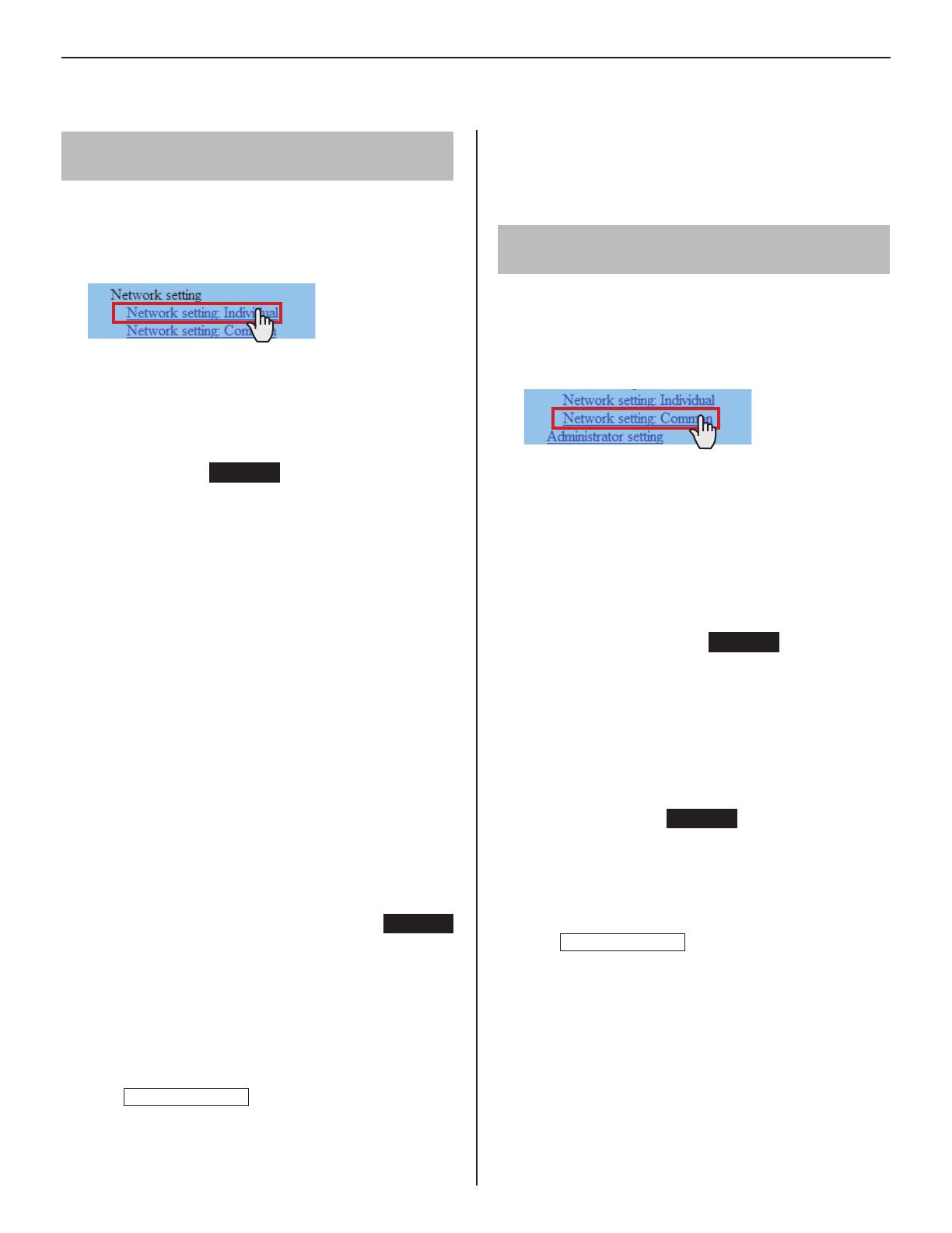
Click
1
Network setting: Individual in the table of
contents.
Make the settings on the following items displayed in
2
the setting window.
[Host unit setting]:
Set this unit as either “Host unit” or “Client unit”. When set to
“Client unit”, also enter the IP address of the IP host unit.
[System name]:
Required
When “Host unit” is selected at [Host unit setting], it is
required to enter a name for this system.
Selecting the network setting method
Set a (static) IP address to this unit. Select the method for acquiring
a (static) IP address between [DHCP] and [Static IP Address].
[DHCP]:
Check this when you will acquire an IP address with DHCP.
A DHCP server (or a router) is required to acquire an
*
IP address with DHCP. A router may not have the setup
function depending on some models. For information about
setting a router, see the instruction manual for the router.
[Static IP Address]:
Check this when you set the static IP address manually,
and then enter the static IP address suitable for the
network you are using, subnet mask, etc.
It is required to enter the static IP address and
*
subnet mask.
[Unit name]:
Enter a name for this unit.
* This name is used for searching for this unit in the
network. If not named, this unit is recognized only by
the unit (station) type and MAC address.
[Connection port], [Connection Password]:
Required
Enter the port number for controlling communication and the
password for security. Use the same port number and password
among the IP host unit and IP client units within the site.
NOTES:
The IP host unit must not have an IP address identical to the IP
address of a remote site’s IP host unit.
The items that cannot be entered or selected are grayed out.
Click
3
Temporarily stored
to save the current setting
results temporarily.
If you wish to cancel the setting results you have made,
*
click a title in the table of contents or “Refresh” in the
web browser menu.
When the settings on this window have nished, update
4
the system from [Updating the system]. (P. 35)
Making network settings for the whole
system [Network setting: Common]
Make the network settings for the whole system on the
web browser of the IP host unit.
Click
1
Network setting: Common in the table of
contents.
Make the settings on the following items displayed in
2
the setting window.
[UPnP]:
If you do not use UPnP, set [UPnP] to OFF.
[Global IP address]:
When [UPnP] is set to OFF, enter the static global IP
address of the router for use in your site.
[Multicast address 1 – 5]:
Required
Enter the multicast addresses for the following:
1: For sound communication for paging between sites
2: For sound communication for paging in your site
3: For sound communication for chime
4: For video communication in your site
5: For video communication between sites
Do not use multicast addresses that overlap those of
*
other devices connected to the same network.
[Audio/video port]:
Required
Enter the port numbers used for audio and video
communication.
Do not use port numbers that overlap those of other
*
devices connected to the same network.
Click
3
Temporarily stored
to save the current setting
results temporarily.
If you wish to cancel the setting results you have made,
*
click a title in the table of contents or “Refresh” in the
web browser menu.
The following shows the setting procedure for the items of each title.
Refer to “SETTING LIST” (P. 5-10) for details about the settings. Make the settings by also referring to the on-screen instructions.
20
Setting the administrator ID and password
[Administrator setting]
We recommend that you change the administrator ID and
password from default to unique ones for security purposes.
This setting can be made to each of the IP units in your site.
*
“aiphone” is preset as the default for both ID and password.
*
Click
1
Administrator setting in the table of contents.
Make the settings on the following items displayed in
2
the setting window.
[New administrator ID]:
Enter the new ID.
[Current Password]:
Enter the current password.
[New Password]:
Enter a new password.
[New Password (Re-type)]:
Enter the new password again.
Click
3
Temporarily stored
to save the current setting
results temporarily.
If you wish to cancel the setting results you have made,
*
click a title in the table of contents or “Refresh” in the
web browser menu.
NOTE:
The system administrator must keep the ID and password without
fail. If you forget the ID and password, you must initialize the unit,
thus all the setting contents return to default.
Con rming the IP units connected to the
system [IP unit search]
Before con guring system wide settings, con rm the IP
units are connected to the network, and set the network
setting for each IP unit using [IP unit search].
Click
1
IP unit search in the table of contents.
Click
2
IP unit search
.
All the IP units connected to the system are displayed in
the list.
If IP units are not displayed, repeat this step until
*
displayed.
Con rm the “Station type”, “MAC address” and “Unit
3
name” of the IP units in the list.
To make or change settings to an IP unit,
4
check the box for the target IP unit and click
Open the setting window
.
Another window opens. You can make settings for the
target IP unit individually.
(P. 19)
Close the window.
5
Repeat step
*
3 to 5 to make settings to other IP units.
NOTES:
This procedure cannot search for PC master stations (IS-SOFT)
and it is not a system failure. To add a PC master station (IS-SOFT)
in the system, install the application (IS-SOFT) to a PC before
connecting it to the network and see page 22.
It may be required to log in to open the setting window, and update
the system at [
Updating the system
] before closing the window.
  • Page 1 1
  • Page 2 2
  • Page 3 3
  • Page 4 4
  • Page 5 5
  • Page 6 6
  • Page 7 7
  • Page 8 8
  • Page 9 9
  • Page 10 10
  • Page 11 11
  • Page 12 12
  • Page 13 13
  • Page 14 14
  • Page 15 15
  • Page 16 16
  • Page 17 17
  • Page 18 18
  • Page 19 19
  • Page 20 20
  • Page 21 21
  • Page 22 22
  • Page 23 23
  • Page 24 24
  • Page 25 25
  • Page 26 26
  • Page 27 27
  • Page 28 28
  • Page 29 29
  • Page 30 30
  • Page 31 31
  • Page 32 32
  • Page 33 33
  • Page 34 34
  • Page 35 35
  • Page 36 36
  • Page 37 37
  • Page 38 38
  • Page 39 39

Aiphone IS User manual

Type
User manual
This manual is also suitable for

Ask a question and I''ll find the answer in the document

Finding information in a document is now easier with AI