Hilti pos 150 User manual
- Category
- Measuring, testing & control
- Type
- User manual
This manual is also suitable for

POS 150/180 English
Printed: 24.04.2018 | Doc-Nr: PUB / 5153820 / 000 / 05

Printed: 24.04.2018 | Doc-Nr: PUB / 5153820 / 000 / 05

English 1
1 Information about the documentation
1.1 About this documentation
• Read this documentation before initial operation or use. This is a prerequisite for safe, trouble-free
handling and use of the product.
• Observe the safety instructions and warnings in this documentation and on the product.
• Always keep the operating instructions with the product and make sure that the operating instructions
are with the product when it is given to other persons.
1.2 Explanation of symbols used
1.2.1 Warnings
Warnings alert persons to hazards that occur when handling or using the product. The following signal words
are used:
DANGER
DANGER !
▶Draws attention to imminent danger that will lead to serious personal injury or fatality.
WARNING
WARNING !
▶Draws attention to a potential threat of danger that can lead to serious injury or fatality.
CAUTION
CAUTION !
▶Draws attention to a potentially dangerous situation that could lead to slight personal injury or damage
to the equipment or other property.
1.2.2 Symbols in the documentation
The following symbols are used in this document:
Read the operating instructions before use.
Instructions for use and other useful information
Dealing with recyclable materials
Do not dispose of electric equipment and batteries as household waste
1.2.3 Symbols in the illustrations
The following symbols are used in illustrations:
These numbers refer to the corresponding illustrations found at the beginning of these operating
instructions
The numbering reflects the sequence of operations shown in the illustrations and may deviate
from the steps described in the text
Item reference numbers are used in the overview illustrations and refer to the numbers used in
the product overview section
This symbol is intended to draw special attention to certain points when handling the product.
Wireless data transfer
Printed: 24.04.2018 | Doc-Nr: PUB / 5153820 / 000 / 05

2 English
1.3 Labels on the POS 150/180
The following labels are applied to the POS 150/180:
Laser radiation. Do not look straight into the laser beam. Laser class
3R.
1.4 Product information
products are designed for professional users and only trained, authorized personnel are permitted
to operate, service and maintain the products. This personnel must be specifically informed about the
possible hazards. The product and its ancillary equipment can present hazards if used incorrectly by
untrained personnel or if used not in accordance with the intended use.
The type designation and serial number are printed on the rating plate.
▶Write down the serial number in the table below. You will be required to state the product details when
contacting Hilti Service or your local Hilti organization to inquire about the product.
Product information
Type: POS 150/180
Generation: 01
Serial no.:
1.5 Declaration of conformity
We declare, on our sole responsibility, that the product described here complies with the applicable directives
and standards. A copy of the declaration of conformity can be found at the end of this documentation.
The technical documentation is filed and stored here:
Hilti Entwicklungsgesellschaft mbH | Tool Certification | Hiltistraße 6 | 86916 Kaufering, DE
2 Safety
2.1 General safety instructions, scanning tools
WARNING! Read all safety precautions and other instructions. Failure to observe the safety
instructions and other instructions can result in electric shock, fire and/or serious injury.
Keep all safety precautions and instructions for future reference.
Work area safety
▶Keep your workplace clean and well lit. Cluttered or poorly lit workplaces invite accidents.
▶Do not operate the product in explosive atmospheres, such as in the presence of flammable liquids,
gases or dust. Scanning tools create sparks which can ignite dust, fumes or vapors.
▶Keep children and other persons clear when the product is in use. Distractions can cause you to
lose control of the product.
Electrical safety
▶Do not expose the product to rain or moisture. Water entering the product will increase the risk of electric
shock.
Personal safety
▶Stay alert, watch what you are doing and use common sense when operating a scanning tool. Do
not use a scanning tool while you are tired or under the influence of drugs, alcohol or medication. A
moment of inattention while operating the scanning tool can result in serious personal injury.
Printed: 24.04.2018 | Doc-Nr: PUB / 5153820 / 000 / 05

English 3
▶Adopt the correct posture when working. Maintain proper footing and balance at all times. This
will allow you to control the scanning tool better, even in unexpected situations.
▶Wear your personal protective equipment and always wear protective glasses. Depending on the
type of scanning tool you are using and its purpose, wearing safety equipment such as a dust mask,
slip-resistant safety shoes, a hard hat or hearing protection will reduce the risk of injury.
▶Avoid starting the tool accidentally. Make sure that the scanning tool is switched off before
connecting it to the battery and before picking it up or carrying it. Carrying scanning tools with your
finger on the switch or plugging in scanning tools that are already switched on can cause accidents.
Using and handling the scanning tool
▶Do not use a scanning tool if it has a faulty on/off switch. A scanning tool that can no longer be
switched on or off is dangerous and must be repaired.
▶Store scanning tools out of reach of children when not in use. Do not allow persons who are not familiar
with the product or these instructions to operate it. Scanning tools are dangerous in the hands of
inexperienced persons.
▶Scanning tools need care and attention. Check that moving parts operate satisfactorily and do not
jam, and make sure that no parts are broken or damaged in such a way that the scanning tool might no
longer function correctly. Have damaged parts repaired before using the scanning tool. Many accidents
are caused by poorly maintained scanning tools.
Using and handling the cordless power tool
▶Use only the specified batteries in the scanning tools. Use of other batteries can result in injury and a
risk of fire.
▶Recharge the batteries only with the chargers recommended by the manufacturer. A charger that is
suitable for a certain type of battery can be a fire hazard if used with other batteries.
▶When the battery is not in use, keep it away from other metal objects such as paper clips, coins,
keys, nails, screws, or other small metal objects that could cause bridging between the terminals.
A short circuit between the battery terminals may cause burns or a fire.
▶Liquid may leak from the battery if used incorrectly. Avoid contact with this liquid. Liquid leaking
from the battery may cause skin irritation or burns. If contact accidentally occurs, rinse with water. Seek
medical attention if the liquid comes into contact with the eyes.
2.2 Battery use and care
▶Observe the special regulations and instructions applicable to the transport, storage and use of Li-ion
batteries.
▶Do not expose batteries to high temperatures, direct sunlight or fire.
▶Do not disassemble, crush or incinerate batteries and do not subject them to temperatures over 80 °C.
▶Do not use or charge batteries that have suffered mechanical impact, have been dropped from a height
or show signs of damage. In this case, always contact your Hilti Service.
▶If the battery is too hot to touch it may be defective. In this case, place the product in a non-flammable
location, well away from flammable materials, where it can be kept under observation and allowed to
cool down. In this case, always contact your Hilti Service.
2.3 Safety instructions, total station
▶Do not render safety devices ineffective and do not remove information and warning notices.
▶If the product is opened improperly, laser radiation in excess of Class 2 may be emitted. Have the
product repaired by Hilti Service only.
▶Check that the product functions correctly each time before use.
▶Measurements taken through panes of glass or other objects may be inaccurate.
▶The measurement may be incorrect if the conditions under which the measurement is taken change
rapidly, e.g. due to people walking through the path of the laser beam.
▶Observe the information printed in the operating instructions concerning operation, care and maintenance.
▶Do not use the product as a level.
▶Do not point the product toward the sun or other powerful light sources.
▶Although the product is designed for the tough conditions of construction site use, as with other
measuring instruments it should be treated with care.
▶Check the accuracy of the product after it has been dropped or subjected to other mechanical stresses.
▶Secure the site at which you are taking measurements and take care to avoid directing the laser beam
toward other persons or toward yourself.
Printed: 24.04.2018 | Doc-Nr: PUB / 5153820 / 000 / 05

4 English
▶When the product is brought into a warm environment from very cold conditions, or vice-versa, allow it
to become acclimatized before use.
▶Keep the laser exit window clean in order to avoid measurement errors.
▶Observe the accident prevention regulations applicable in your country.
▶Use the product only within its specified limits.
▶Precautions must be taken to ensure that the laser beam does not unintentionally strike highly reflective
surfaces.
▶Precautions must be taken to ensure that persons do not stare directly into the beam.
▶The laser beam must not be allowed to project beyond the controlled area.
▶Switch the laser tool off when it is not in use.
▶When switching distance measurement from prism measurement to reflectorless measurement, make
sure that you do not look at the objective lens of the tool.
▶View the tool at an angle when setting it up with the aid of the circular bubble level.
▶Laser beams should not be projected at eye height.
▶The specified operating and storage temperatures must be observed.
2.4 Electromagnetic compatibility
Although the tool complies with the strict requirements of the applicable directives, Hilti cannot entirely rule
out the possibility of interference to the tool caused by powerful electromagnetic radiation, possibly leading
to incorrect operation. Check the accuracy of the tool by taking measurements by other means when working
under such conditions or if you are unsure. Likewise, Hilti cannot rule out the possibility of interference with
other devices (e.g. aircraft navigation equipment). The tool complies with the requirements of Class A; the
possibility of interference occurring in a domestic environment cannot be excluded.
Only for Korea: This laser range meter is suitable for commercial and industrial use and for the electromagnetic
radiation encountered in this field (Class A). Users must pay attention to this point and make sure that this
laser range meter is not used in a domestic environment.
Printed: 24.04.2018 | Doc-Nr: PUB / 5153820 / 000 / 05

English 5
3 Description
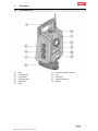
3.1 Total station front
@Grip
;Focusing knob
=Vertical drive
%Horizontal drive
&Tripod lock
(Sight
)Telescope with laser distancer
+Lens
§Guide light
/Operator keyboard
:Display
Printed: 24.04.2018 | Doc-Nr: PUB / 5153820 / 000 / 05

6 English
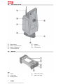
3.2 Total station rear side
∙Radio antenna
$Battery compartment lock
£Battery compartment
|Circular bubble level
¡Eyepiece
QTripod screw
WLaser plummet
3.3 POC 100
Key
@Display
;Control panel
=Charging socket
%USB socket (master)
&USB socket (slave)
Printed: 24.04.2018 | Doc-Nr: PUB / 5153820 / 000 / 05

English 7
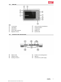
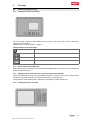
3.4 POC 200
Key
@Touchscreen
;LED display
=Microphone
%Eye for theft protection
&Brightness sensor
(4-way controller and OK button
)4 function buttons
+Loudspeaker
§Display lock
/On/off switch
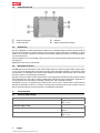
3.5 Connector side of the POC 200
:HDMI socket
∙Headset socket
$Docking connector
£Socket for the docking station
|USB port
¡Connection for power supply
Printed: 24.04.2018 | Doc-Nr: PUB / 5153820 / 000 / 05

8 English
3.6 Underside, POC 200
QHolder for stylus/pen
WCamera and flash
EBatteries
RBattery charge status indicator
3.7 Intended use
The tool is designed for measuring distances and directions, calculating target positions in three dimensions
and the values derived from these positions and for laying out points using given coordinates or values
relative to a control line. Observe the information printed in the operating instructions concerning operation,
care and maintenance.
Take the influences of the surrounding area into account. Do not use the machine where there is a risk of fire
and explosion.
Modification of the tool is not permitted.
3.8 Description of the tool
The Hilti POS 150/180 total station can be used to define objects as dynamic positions within a given space
or area. The tool is equipped with horizontal and vertical circles with digital graduation, two electronic levels
(compensators), a coaxial electronic distance meter (EDM) incorporated in the telescope and an electronic
processor system for calculating and saving data.
The built-in target acquisition system allows prisms to be targeted automatically and their positions tracked
even when they move. The prism’s position is determined continuously and processed in the application on
an ongoing basis. The total station is operated using the POC 100 or POC 200 controller.
Hilti PROFIS Layout, a PC application provided by Hilti, can be used to transfer data in both directions
between the total station and a PC, for data processing and for exporting data to other systems. Data can
also be transferred directly from the controller to a USB data storage device.
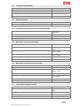
4 Technical data
4.1 Telescope (POS 150/180)
Telescope magnification 31 x
Shortest target distance 1.5 m
(4 ft - 11 in)
Telescope angle of view 1° 30'
Lens aperture 50 mm
(2.0 in)
Minimum focus distance 1.5 m
(4 ft - 11 in)
Printed: 24.04.2018 | Doc-Nr: PUB / 5153820 / 000 / 05

English 9
4.2 Compensator (POS 150/180)
Type Dual-axis, liquid
Range, fine ± 5.5'
Range, coarse ± 3°
Accuracy 0.5"
Sensitivity to tribrach circular bubble level ± 8' / 2 mm
4.3 Angle measurement
POS 150 accuracy (DIN 18723) 5"
POS 180 accuracy (DIN 18723) 3"
4.4 Laser distance measurement / laser pointer (POS 150/180)
Wavelength 660 nm
(0.0000260 in)
Laser class 3 R
Beam divergence 0.27 mrad
Maximum output power < 5 mW
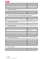
4.5 Measuring mode (prism, POS 150/180)
Laser class 3 R
Range (single prism) 1,000 m
(3,280 ft - 10 in)
Accuracy (standard) ± 2 mm + 2 ppm
(0.01 ft + 2 ppm)
Accuracy (tracking) ±5 mm + 2 ppm
(0.02 ft + 2 ppm)
Measuring time (standard) 2.5 s
Measuring time (tracking) 0.5 s
4.6 Measuring mode (reflectorless, POS 150/180)
Laser class 3R
Range KGC 90%: 600 m (1970 ft)
Range with reflective foil 800 m
(2,624 ft - 10 in)
Accuracy (standard) ±3 mm + 2 ppm (0.1 ft + 2 ppm)
Accuracy (tracking) ±10 mm + 2 ppm
(0.4 ft + 2 ppm)
Measuring time (standard) 3 s …10 s
Measuring time (standard) 0.7 s
4.7 Laser target tracking (POS 150/180)
Laser class 1
Maximum range 300 m
(984 ft)
Pointing precision < 2"
Search times (typical) 2 s …10 s
Beam divergence 40 x 30 mrad
Printed: 24.04.2018 | Doc-Nr: PUB / 5153820 / 000 / 05

10 English
Pulse duration 144 µs
Maximum pulse frequency 109 Hz
Maximum peak power 2.22 mW
Maximum average power 0.035 mW
Wavelength 850 nm
4.8 Motorization (POS 150/180)
Rotation speed max. 90°/s
Telescope repositioning 4 s
Rotation 180° (typical) 3.5 s
4.9 Wireless communication (between the POS 150/180 and POC 100/POC 200)
Frequency range 2,400 MHz …2,483.5 MHz
Maximum emitted transmission power 19.3 dBm
Range 300 m …800 m
(984 ft …2,624 ft - 10 in)
4.10 Interfaces (POC 100/POC 200)
USB External data connection
4.11 Guide light (POS 150/180)
Aperture angle 8°
Light source Red/green
Typical range 70 m
(229 ft - 10 in)
Beam divergence 70 mrad
Maximum output power (red) 0.4 mW
Maximum output power (green) 0.2 mW
Wavelength (red) 645 Nm
Wavelength (green) 520 Nm
4.12 Laser plummet (POS 150/180)
Accuracy 1.5 mm at 1.5 m (1/16 in at 3 ft)
Maximum output power < 5 mW
Wavelength 635 nm
Laser class 3R
Intensity levels 0 …4
Beam divergence 0.6 mrad
4.13 Drives (POS 150/180)
Type (horizontal / vertical) Motorized / continuous
Focus Motorized
Printed: 24.04.2018 | Doc-Nr: PUB / 5153820 / 000 / 05

English 11
4.14 IP protection class
Tool (POS 150/180) IP 55
Controller (POC 100) IP 67
Controller (POC 200) IP 65
4.15 Tripod thread
Tribrach thread 5/8"
4.16 Temperature (POS 150/180, POC 100)
Operating temperature −20 ℃ …50 ℃
(−4 ℉ …122 ℉)
Storage temperature −30 ℃ …70 ℃
(−22 ℉ …158 ℉)
4.17 Temperature (POC 200)
Operating temperature −30 ℃ …60 ℃
(−22 ℉ …140 ℉)
Storage temperature −40 ℃ …70 ℃
(−40 ℉ …158 ℉)
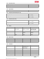
4.18 Display
POS 150/180 POC 100 POC 200
Display Monochrome,
96 x 49 pixels
TFT color touchscreen,
VGA 640 × 480 pixels
TFT capacitive color
touchscreen, VGA
1024 × 600 pixels
Illumination Backlit 5 levels 5 levels
Contrast – Day / night mode se-
lectable
Day / night mode se-
lectable
Control panel 3 buttons and on/off
button
6 buttons and on/off
button
6 buttons and on/off
button
4.19 Power source
POS 150/180 POC 100 POC 200
AC adapter POA 85 POA 81 POA 89
Battery POA 84 POA 80 POA 90
External POA 88 to 12 V
4.20 AC adapter
POS 150/180 POC 100 POC 200
AC adapter POA 85 POA 81 (US:
TR30RAM0) for the
POA 80 battery
POA 89
Supply voltage 100 V …240 V 100 V …240 V 100 V …240 V
AC frequency 50 Hz …60 Hz 50 Hz …60 Hz 50 Hz …60 Hz
Current input – 0.4 A …0.8 A 1.5 A
Power input 100 VA
Output current 3 A 4 A 5 A
Output voltage (DC) 19 V 5 V 12 V
Printed: 24.04.2018 | Doc-Nr: PUB / 5153820 / 000 / 05

12 English
POS 150/180 POC 100 POC 200
Weight 0.32 kg
(0.71 lb)
0.25 kg
(0.55 lb)
0.33 kg
(0.73 lb)
Operating temperature −20 ℃ …40 ℃
(−4 ℉ …104 ℉)
−20 ℃ …40 ℃
(−4 ℉ …104 ℉)
−20 ℃ …40 ℃
(−4 ℉ …104 ℉)
Storage temperature −30 ℃ …70 ℃
(−22 ℉ …158 ℉)
−30 ℃ …70 ℃
(−22 ℉ …158 ℉)
−30 ℃ …70 ℃
(−22 ℉ …158 ℉)
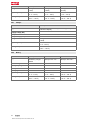
4.21 Charger
POS 150/180
Type POA 86 for the POA 84 battery (POA 86 supplied by
POA 85 AC adapter)
Supply voltage (DC) 19 V
Output current 3 A
Output voltage (DC) 10 V …21 V
Weight 0.18 kg
(0.40 lb)
Operating temperature −20 ℃ …40 ℃
(−4 ℉ …104 ℉)
Storage temperature −30 ℃ …70 ℃
(−22 ℉ …158 ℉)
4.22 Battery
POS 150/180 POC 100 POC 200
Type POA 84, Li-ion; charging
with battery charger
POA 86
POA 80, Li-ion; charging
directly in POC 100
POA 90, Li-ion; charging
directly in POC 200
Rated voltage 11.1 V 3.8 V 7.5 V
Battery capacity 5,000 mAh 5,200 mAh 6,000 mAh
Battery life at 25 °C: 6 hours at 25 °C: 10 hours at 25 °C: 16 hours
Charging time < 4 hours <3 hours < 3 hours
Operating temperature −20 ℃ …45 ℃
(−4 ℉ …113 ℉)
−20 ℃ …50 ℃
(−4 ℉ …122 ℉)
−30 ℃ …60 ℃
(−22 ℉ …140 ℉)
Storage temperature −30 ℃ …70 ℃
(−22 ℉ …158 ℉)
−30 ℃ …70 ℃
(−22 ℉ …158 ℉)
−30 ℃ …70 ℃
(−22 ℉ …158 ℉)
Printed: 24.04.2018 | Doc-Nr: PUB / 5153820 / 000 / 05

English 13
5 First steps
5.1 Controls and display screens
5.1.1 Control panel on the total station
The control panel comprises a 5-line display and four buttons. This control unit is used to make basic
settings on the total station.
Function buttons on the total station → page 13
Function buttons on the total station
Switches the tool on or off
Laser plummet on / off
Shifts focus downwards, rolling
Confirms the selected display.
5.1.2 Set-up with circular bubble level
When starting up the total station the circular bubble level displayed on the screen must be centered by
turning the tripod footscrews.
5.1.3 Setting up over a mark on the floor or ground using the laser plummet
The tool should always be set up over a point marked on the floor or ground so that in case of measurement
deviations it is possible to fall back on the data for the station or orientation point.
The tool features a laser plummet that is switched on automatically together with the tool.
5.1.4 Control panel on the controller
Printed: 24.04.2018 | Doc-Nr: PUB / 5153820 / 000 / 05

14 English
The control panel on the controller consists of a total of 7 buttons with symbols plus a touch screen for
interactive operation.
Function buttons on the controller → page 14
Function buttons on the controller
Switches the tool on or off
Switches the display backlight on or off
Calls up the FNC menu for additional settings
Cancels or ends all active functions and returns to the start menu
User-configured function button
User-configured function button
Control and prism search function button
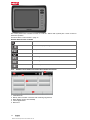
5.1.5 Indicators and controls on the POC 100 controller touchscreen
1. Information bar
2. Battery status, wireless connection and measuring target status
3. Menu display (action, time and date)
4. Various applications
5. Button bar
Printed: 24.04.2018 | Doc-Nr: PUB / 5153820 / 000 / 05

English 15
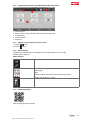
5.1.6 Indicators and controls on the POC 200 controller touchscreen
1. Information bar
2. Battery, status of radio connection and measurement target, time
3. Activated menu
4. Function buttons
5. Button bar
5.1.7 Viewing on-board help for the active screen
1. Press the button.
2. Press the button.
5.1.8 Status displays
Important tool status information is displayed in the top right-hand corner of the screen.
Status indicator → page 15
Status indicator
Compensator on / off
EDM
Active target
Type
Setting including status laser pointer and the laser plummet
Battery state of charge: 0 - 100%
5.1.9 Further information
POS 150 (http://qr.hilti.com/r51292)
Printed: 24.04.2018 | Doc-Nr: PUB / 5153820 / 000 / 05

16 English
POS 180 (http://qr.hilti.com/r51294)
6 Calibration and adjustment
6.1 Calibration review
The tool is correctly adjusted when supplied. The values to which the tool is set may change over time or
due to temperature fluctuations, transport or aging. The tool therefore incorporates a feature that allows the
settings to be checked and, if necessary, corrected by carrying out in-the-field re-calibration. This is done
by setting up the tool securely on a tripod of good quality and targeting an easily visible, clearly discernible
prism within ±3 degrees of horizontal at a distance of approx. 50 - 70 m.
After this, follow the instructions on the display.
Tool parameters that are checked by in-the-field calibration and electronically adjusted:
• Target axis errors
• VA collimation errors
• Inclination errors of the tilt sensor (compensator)
• Axis errors of the automatic prism targeting system (prism tracker)
Laser pointer to cross hairs alignment error can be checked in the field. If the error is excessive, please
contact the Hilti Tool Service or the Hilti Repair Service, as this error requires mechanical correction.
As the Hilti total station system is primarily used for measuring applications in one position, it is advisable to
calibrate the tool in the field or on the construction site at regular intervals. This is especially the case when
steeper sightings are used frequently.
7 Transport and storage of cordless tools
Transport
CAUTION
Accidental starting during transport !
▶Always transport your products with the batteries removed!
▶Remove the battery.
▶Transport the tool and batteries individually packaged.
▶Never transport batteries in bulk form (loose, unprotected).
▶Check the tool and batteries for damage before use after long periods of transport.
Storage
CAUTION
Accidental damage caused by defective or leaking batteries !
▶Always store your products with the batteries removed!
▶Store the tool and batteries in a place that is as cool and dry as possible.
▶Never store batteries in direct sunlight, on heating units or behind a window pane.
▶Store the tool and batteries in a place where they cannot be accessed by children or unauthorized
persons.
▶Check the tool and batteries for damage before use after long periods of storage.
Printed: 24.04.2018 | Doc-Nr: PUB / 5153820 / 000 / 05

English 17
7.1 Care and maintenance
WARNING
Risk of injury with battery inserted !
▶Always remove the battery before carrying out care and maintenance tasks!
Care and maintenance of the tool
• Carefully remove stubborn dirt from the tool.
• Use only a slightly damp cloth to clean the casing. Do not use cleaning agents containing silicone as
these may attack the plastic parts.
Care of the Liion batteries
• Keep the battery free from oil and grease.
• Use only a slightly damp cloth to clean the casing. Do not use cleaning agents containing silicone as
these may attack the plastic parts.
• Avoid ingress of moisture.
Maintenance
• Check all visible parts and controls for signs of damage at regular intervals and make sure that they all
function correctly.
• Do not operate the cordless tool if signs of damage are found or if parts malfunction. Have the tool
repaired by Hilti Service immediately.
• After cleaning and maintenance, fit all guards or protective devices and check that they function correctly.
Cleaning the lens
ATTENTION
Risk of damage The optical system may be damaged by touching the parts.
▶Do not touch the glass surfaces with your fingers.
▶Blow any dust off the glass.
▶Use only a soft, clean cloth to clean the tool.
7.2 Hilti Measuring Systems Service
Hilti Measuring Systems Service checks the scanning tool and, if deviations from the specified accuracy are
found, recalibrates it and rechecks to ensure conformity with specifications. The service certificate provides
written confirmation of conformity with specifications at the time of the test. The following is recommended:
• Choose a test/inspection interval that matches usage of the device.
• Have the product checked by Hilti Measuring Systems Service after exceptionally heavy use or subjection
to unusual conditions or stress, before important work or at least once a year.
Testing and inspection by Hilti Measuring Systems Service does not relieve the user of the obligation to
check the scanning tool before and during use.
8 Troubleshooting
8.1 Total station / controller is not in working order
Trouble or fault Possible cause Action to be taken
The tool can’t be switched
on.
The battery is discharged or not
correctly inserted.
▶Change the battery and charge
the empty battery.
▶Insert the battery correctly.
▶Contact HILTI service.
Printed: 24.04.2018 | Doc-Nr: PUB / 5153820 / 000 / 05

18 English
9 Disposal
WARNING
Risk of injury. Hazards presented by improper disposal.
▶Improper disposal of the equipment may have the following consequences: The burning of plastic
components generates toxic fumes which may present a health hazard. Batteries may explode if
damaged or exposed to very high temperatures, causing poisoning, burns, acid burns or environmental
pollution. Careless disposal may permit unauthorized and improper use of the equipment. This may
result in serious personal injury, injury to third parties and pollution of the environment.
Most of the materials from which Hilti products are manufactured can be recycled. The materials must be
correctly separated before they can be recycled. In many countries, your old tools, machines or appliances
can be returned to Hilti for recycling. Ask Hilti Service or your Hilti sales representative for further information.
In accordance with the European Directive on waste electrical and electronic equipment and its implemen-
tation in conformance with national law, electric tools or appliances that have reached the end of their life
must be collected separately and returned to an environmentally compatible recycling facility.
▶Disposal of electric tools or appliances together with household waste is not permissible.
10 Manufacturer’s warranty
▶Please contact your local Hilti representative if you have questions about the warranty conditions.
11 FCC statement (applicable in US) / IC statement (applicable in Canada)
This equipment has been tested and found to comply with the limits for a class B digital device,
pursuant to part 15 of the FCC rules. These limits are designed to provide reasonable protection
against harmful interference in a residential installation. This equipment generates, uses, and can
radiate radio frequency energy and, if not installed and used in accordance with the instructions, may
cause interference to radio communications.
However, there is no guarantee that interference will not occur in a particular installation. If this equipment
does cause harmful interference to radio or television reception, which can be determined by turning the
equipment off and on, the user is encouraged to try to correct the interference by taking the following
measures:
• Re-orient or relocate the receiving antenna.
• Increase the separation between the equipment and receiver.
• Connect the equipment to a power outlet on a circuit different from that to which the receiver is
connected.
• Consult the dealer or an experienced TV/radio technician for assistance.
Changes or modifications not expressly approved by Hilti may restrict the user’s authorization to
operate the equipment.
This device is in compliance with paragraph 15 of the FCC Regulations and RSS-210 of the ISED Regulations.
Operation is subject to the following two conditions:
• This device shall cause no harmful interference.
• This device must accept any interference received, including interference that may cause undesired
operation.
Printed: 24.04.2018 | Doc-Nr: PUB / 5153820 / 000 / 05
Page is loading ...
Page is loading ...
Page is loading ...
Page is loading ...
-
 1
1
-
 2
2
-
 3
3
-
 4
4
-
 5
5
-
 6
6
-
 7
7
-
 8
8
-
 9
9
-
 10
10
-
 11
11
-
 12
12
-
 13
13
-
 14
14
-
 15
15
-
 16
16
-
 17
17
-
 18
18
-
 19
19
-
 20
20
-
 21
21
-
 22
22
-
 23
23
-
 24
24


Hilti pos 150 User manual
- Category
- Measuring, testing & control
- Type
- User manual
- This manual is also suitable for
Ask a question and I''ll find the answer in the document
Finding information in a document is now easier with AI
Related papers
-
Hilti PR 30 Operating instructions
-
Hilti PR 3-HVS Operating instructions
-
-
-
-
-
-
-
Hilti PLT 300 Operating instructions
-
Other documents
-
Sokkia FX-200 Series Onboard Total Station User manual
-
-
AMX AXT-CV TiltScreen CATP User manual
-
-
-
-
Sokkia SET Total Station User manual
-
-
 STONEX R6 Series User manual
-
 Manson Engineering Industrial USB-2928 Quick start guide

