Hilti POT 10 Operating instructions
- Category
- Measuring, testing & control
- Type
- Operating instructions
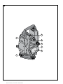
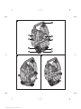
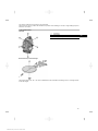
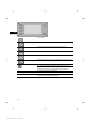
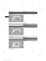
Hilti POT 10 is a theodolite that can be used for a variety of angle measurements and leveling tasks. The tilt axis scale allows you to precisely measure horizontal angles, while the vertical circle allows for accurate measurement vertical angles. You can use the laser plummet to quickly and accurately set up the tool and establish a vertical point of reference, making it ideal for tasks such as setting out foundations and transferring heights.
Hilti POT 10 is a theodolite that can be used for a variety of angle measurements and leveling tasks. The tilt axis scale allows you to precisely measure horizontal angles, while the vertical circle allows for accurate measurement vertical angles. You can use the laser plummet to quickly and accurately set up the tool and establish a vertical point of reference, making it ideal for tasks such as setting out foundations and transferring heights.


-
 1
1
-
 2
2
-
 3
3
-
 4
4
-
 5
5
-
 6
6
-
 7
7
-
 8
8
-
 9
9
-
 10
10
-
 11
11
-
 12
12
-
 13
13
-
 14
14
-
 15
15
-
 16
16
-
 17
17
-
 18
18
-
 19
19
-
 20
20
-
 21
21
-
 22
22
-
 23
23
-
 24
24
-
 25
25
-
 26
26


Hilti POT 10 Operating instructions
- Category
- Measuring, testing & control
- Type
- Operating instructions
Hilti POT 10 is a theodolite that can be used for a variety of angle measurements and leveling tasks. The tilt axis scale allows you to precisely measure horizontal angles, while the vertical circle allows for accurate measurement vertical angles. You can use the laser plummet to quickly and accurately set up the tool and establish a vertical point of reference, making it ideal for tasks such as setting out foundations and transferring heights.
Ask a question and I''ll find the answer in the document
Finding information in a document is now easier with AI
Related papers
-
Hilti POT 10 User manual
-
Hilti PRA 30 Operating instructions
-
-
Hilti 411210 Owner's manual
-
-
-
-
Hilti PD 5 Operating instructions
-
Hilti PD-E Operating Instructions Manual
-
Other documents
-
Kmart 43105908 User manual
-
ADA INSTRUMENTS А00572 Cube 3-360 Line Laser User manual
-
Sokkia FX-200 Series Onboard Total Station User manual
-
-
Topcon Synergy GM-50 series User manual
-
AMX AXT-CV TiltScreen CATP User manual
-
-
-
Bosch GLL 100 GX User manual
-