Page is loading ...

1
Pre-Installation
1. Determine the number of controls to be ganged
in the same wallbox. Allow the space equivalent of a
full wallbox for EVERY control to be installed.
2. If more than one control is being ganged in the
same wallbox, side sections must be removed for
proper fit. When controlling magnetic ballasts,
breaking side sections off the control will reduce the
maximum number of lamps per control. Use the
following charts to determine the maximum capacity
of each control.
3. Remove desired inner side sections. Using pliers,
bend side sections down as far as possible and then
back to their original position. See diagrams below.
Side sections will break off. Do not remove outer side
sections of controls on the ends of the installation.
These products are covered under one or more of the following U.S. patents:
4,663,570; 4,833,277; 4,835,816; 4,894,587; 5,001,386; 5,041,763; 5,173,643 and
corresponding foreign patents. U.S. and Foreign patents pending. Lutron, Hi-lume,
and Skylark are registered trademarks. Claro is a trademark of Lutron Electronics
Co., Inc.
©©
©©
©1996 Lutron Electronics Co., Inc.
Installation Instructions
Please Leave for Occupant
Fluorescent Dimmers
SF-12P-277, SF-12P-277-3
277VAC, 60Hz
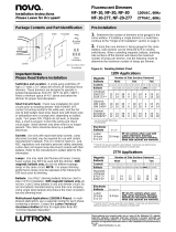
Package Contents and Part Identification
Important Notes
Please Read Before Installation
Wallbox and Location: A single-gang wallbox (3"
high x 2" wide x 2
1
/2" deep) will service all individual
Skylark dimmers. These dimmers are designed to
operate in ambient temperatures from 0
o
C (32
o
F) to
40
o
C (104
o
F). Allow a minimum space of 4
1
/2" above
and below the dimmer for proper heat dissipation.
Short Circuit Check: Check new installation for
short circuits prior to installation of dimmer by
connecting incoming hot wire to ballast input wires
with POWER OFF. Magnetic ballast: Connect the
black and brown or black and yellow/blue wires
together. Electronic ballast: Connect the black and
orange wires together. Turn power on. If lights do not
work, or breaker trips, a short is present. Correct the
wiring and check circuit again. Install dimmer only
when short is no longer present. This check should
be done by a qualified electrician.
Sockets: For magnetic ballasts, use lamp disconnect
sockets only. This meets U.L. and NEC regulations
and maintains personal safety standards. For
electronic ballasts, knife edge sockets are
recommended.
Lamps: Energy Saver Lamps may NOT be used with
this dimmer. With magnetic ballasts only, do not mix
different wattage lamps in the same circuit. NOTE:
Greater dimming range is achieved by operating
lamps at full intensity for 100 hours.
Magnetic ballasts: Use ONLY dimming ballasts
shown on chart in step 2 of Pre-Installation. Do not
mix 1 and 2 lamp ballasts in any one dimmer circuit.
Do not mix ballast manufactured by more than one
company. Using single lamp ballasts will produce the
most consistent low end dimming level.
Multi-phase Applications: In multi-phase
applications use a separate neutral for each phase
containing a dimmer. Contact the
Lutron Technical
Assistance Hotline
toll-free for Application Note
#17, "Common Neutral Interaction".
No Side
Sections
Removed
One Side
Section
Removed
Middle Unit Has
Two Side Sections
Removed
Electronic Side Sections Removed
Ballasts None One Two
Lutron
Hi-lume 6 amps 6 amps 6 amps
Eco-10 6 amps 6 amps 6 amps
Electronic Ballasts: Maximum current per control
Magnetic Ballasts: Maximum number of lamps per
control
Magnetic Side Sections Removed
Ballasts None One Two
Universal
679-L-TC-P 12 lamps 10 lamps 8 lamps
678-A-TC-P* 12 lamps 10 lamps 8 lamps
* 2 lamp ballast
Mounting Hole
Slider
Low-end
Adjustment
Thumbwheel
On/Off
Rocker
Switch
Side
Section
Breakoffs
2 Mounting Screws
6 Wire
Connectors
(SF-12P-277-3)
5 Wire
Connectors
(SF-12P-277)

2
SF-12P-277 with Magnetic Dimming
Ballast
Installation
1. TURN OFF POWER at fusebox or circuit
breaker. Wiring with power on can result in personal
injury or product damage. Damage caused by wiring
with power on will void the warranty.
2. Wire connectors supplied can be used to join one
10-, 12-, 14-, 16-, or 18-gauge wire with one or two
12-, or 14-gauge wires. Wire connectors are suitable
for use with copper wire ONLY.
Strip wallbox wires to the following lengths:
1/2" for 10, 12, and 14 gauge wire
5/8" for 16 and 18 gauge wire
3. Using wire connectors supplied, make
connections following the appropriate wiring
diagrams for your combination of controls and
ballasts.
4. Carefully push and form wires into wallbox while
keeping wire connectors toward the top and bottom
corners to allow room for the dimmer backcover. Do
not pinch wires.
5. Mount dimmer to wallbox using screws provided.
Unit MUST be mounted vertically.
6. Turn power ON.
7. For magnetic ballasts ONLY:
Adjust minimum light intensity as follows:
a) Run lamps at full intensity (slider at top position)
for 15 minutes to warm ballasts.
b) After 15 minutes push slider to low intensity
position.
c) Locate thumbwheel adjustment (shown in Package
Contents and Part Identification on page 1).
d) Rotate the thumbwheel to raise or lower minimum
light intensity. Proper minimum light intensity is set
when lamps do not flicker or drop out.
For Lutron electronic ballasts ONLY:
This unit is factory-calibrated and does not normally
require low-end light adjustment when used with
Lutron FDB or ECO-10 electronic ballasts. If lamps
flicker or drop out at minimum dimming level there
may be an installation error or the low-end light level
may need to be reset. Continued use of the system in
this mode will cause premature lamp failure. If this
condition exists, call the
Lutron Technical
Assistance Hotline
at: 1-800-523-9466.
1/2" or 5/8"
SF-12P-277 with two lamp ballast
Red
Dimmer
Hot
Neutral
277VAC
60Hz
Ground
Green or
Bare
White
Yellow
Black
Lamp
Magnetic Dimming Ballast
*
* Lamp
Disconnect
Socket
White
Black
Red
Red
Yellow/Blue or Brown
Blue
Red
Dimmer
Hot
Neutral
277VAC
60Hz
Ground
Green or
Bare
White
Yellow
Black
Lamp
*
* Lamp
Disconnect
Socket
Blue/White
White
Black
Red
Red
Yellow/Blue or Brown
Lamp
*
Yellow
Yellow
Blue
Magnetic Dimming Ballast
SF-12P-277 wallbox wiring
White
Yellow
Neutral
Hot
Switched Hot
Black
Red
Control
Ground
Green or Bare
SF-12P-277 with one lamp ballast

3
SF-12P-277-3 with Magnetic Dimming
Ballast
SF-12P-277 with Lutron Dimming Ballast
Black
Red
Dimmer
Hot
Neutral
277VAC
60Hz
Ground
Green or
Bare
White
Yellow
To Additional Ballasts
Orange
Black
White
Orange
Black
White
Lutron Dimming Ballast
Lutron Dimming Ballast
SF-12P-277 with Lutron electronic ballast
SF-12P-277 wallbox wiring
White
Yellow
Neutral
Hot
Switched Hot
Black
Red
Control
Ground
Green or Bare
SF-12P-277-3 with one lamp ballast
SF-12P-277-3 wallbox wiring
White
Yellow
Neutral
Switch Hot
Traveler 1
Red
Blue
Control
Ground
Green or Bare
Traveler 2
Blue
Blue
Red
Dimmer
Hot
Neutral
277VAC
60Hz
Ground
Green or
Bare
White
Yellow
Blue
3-Way
Switch
Lamp
*
* Lamp
Disconnect
Socket
White
Black
Red
Red
Yellow/Blue or Brown
Blue
Magnetic Dimming Ballast
Blue
Red
Dimmer
Hot
Neutral
277VAC
60Hz
Ground
Green or
Bare
White
Yellow
Blue
3-Way
Switch
Lamp
*
* Lamp
Disconnect
Socket
Blue/White
White
Black
Red
Red
Yellow/Blue or Brown
Lamp
*
Yellow
Yellow
Blue
Magnetic Dimming Ballast
SF-12P-277-3 with two lamp ballast
NOTE: If the SF-12P-277-3 does not turn off, or the
unit does not turn on at all, the red and blue wires
have been connected incorrectly. The result of the
miswire depends on the position of the other 3-Way
switch. Check the wiring carefully.
SF-12P-277-3 with Lutron electronic ballast
Blue
Red
Dimmer
Hot
Neutral
277VAC
60Hz
Ground
Green or
Bare
White
Yellow
To Additional Ballasts
Orange
Black
White
Orange
Black
White
Lutron Dimming Ballast
Lutron Dimming Ballast
Blue
3-Way
Switch
SF-12P-277-3 wallbox wiring
White
Yellow
Neutral
Switch Hot
Traveler 1
Red
Blue
Control
Ground
Green or Bare
Traveler 2
Blue
SF-12P-277-3 with Lutron Dimming Ballast

4
Warranty
Lutron will, at its option, repair or replace any unit that is defective in materials or
manufacture within one year after purchase. For warranty service, return unit to place
of purchase or mail to LUTRON at 7200 Suter Road, Coopersburg, PA 18036-1299,
postage prepaid.
This warranty is in lieu of all other warranties, express or implied, and the implied
warranty of merchantability is limited to one year from purchase. This warranty
does not cover the cost of installation, removal, or reinstallation, or damage
resulting from misuse, abuse, or damage resulting from improper wiring or
installation.
This warranty gives you specific legal rights, and you may also have other rights which
vary from state to state. Some states do not allow the exclusion or limitation of
incidental or consequential damages or limitations on how long an implied warranty
may last, so the above limitations may not apply to you.
Lutron Electronics Co., Inc.
7200 Suter Road
Coopersburg, PA 18036-1299 U.S.A.
Made and printed in U.S.A. 4/96 P/N 032-050 Rev. A
Worldwide Technical and Sales
Assistance
If you have questions concerning the installation or
operation or this product, call the
Lutron Technical
Assistance Hotline
:
(800) 523-9466 (U.S.A., Canada, and the Caribbean)
Other countries call (610) 282-3800
Fax (610) 282-3090
8. Attach Lutron Claro wallplate or other designer-
style wallplate purchased separately. A beautiful,
clean appearance with no visible screws is provided
by Lutron's Claro wallplate systems.
Single Unit With Claro Wallplate
Multi-Ganged Unit With Claro Wallplate (4 gang max.)
/