Page is loading ...

QUICK BGA 2025
BGA/CSP Rework Station
Operation Manual
Thank you for purchasing our BGA/SMD Rework System. The system is exclusively designed for reworking
and soldering SMD component. Please carefully read this manual before operating the system. Store this
manual in a safe, easily accessible place for future reference.

QUICK2025 manual operation
Page 1
1. Summary
Thank you for using QUICK BGA2025 Rework System. This system, which adopts microprocessor control and
infrared sensor technology to solder and de-solder to surface mount components safely and accurately. It also
can control the whole technical process and record all the information by means of the BGA Software, thus
satisfying the higher technical demands of modern electronic industry. It is one of the most valued electronic
equipments in electronic field.
QUICK BGA2025 Rework System adopts infrared sensor technology and closed–loop principle, integrating
harmoniously the infrared heater and the sirocco heater together. In order to control the soldering process
optimally and get the nondestructive and reproductive PCB temperature, QUICK BGA2025’s heating power is
up to 3500W. Top heater is infrared and the heating power and the heating window are adjustable, infrared
sensor detects the surface temperature of the BGA and the curve of the Temperature can control the detecting
temperature. Bottom heater uses not only the infrared heater but also sirocco heater. The sirocco heater is part
heating to the PCB of the BGA bottom with temperature’s curve controlling and infrared heater is to the whole
PCB with controlling the preheating temperature to prevent the board from transfiguration. For more
preciseness technics demands and effectual controlling the PCB temperature and the encapsulation temperature,
the technology of re-flow soldering controlled by closed-loop ensures the precise and smaller technical window,
even heat distribution and appropriate peak value of temperature for lead-free soldering. Besides, the infrared
heater is suitable for all applications, such as large or small PCB and lead-free solder, moving automatically in
X-axis to heating the PCB evenly.
Optics aligning prism of QUICK BGA2025 Rework System expands to 60*60mm from 40*40mm. Big BGA
alignment can see clearly and the aligning lens are controlled by the step motor and the chip slave is above the
lens. The PCB fixture is square and the maximum size is 600*500mm, the width of the left and right arms can
be adjusted and the abnormity knightheads can be fixed on the arms. On the fixture, there are X
micro-adjusting knob and Y micro-adjusting knob for precise alignment and the bottom knighthead is
connecting with the arm to keep identical placing position of PCB.
For reducing the manual effects, QUICK2025 BGA rework system can automatically run the processes except
adjusting X、Y、θ with hand for precise alignment. Besides, the chip sucking and pasting, lens moving, reflow
controlling, heating moving and chip de-solder are all automatic controlled by the step motor. And the system
has the controlling software with wide screen display of LCD to multi-control the processes unaided or by the
outer computer.
The new BGA rework system has the advantages of the infrared heater and sirocco heater, satisfying the
demands of reworking the BGA, especially in lead-free soldering.

QUICK2025 manual operation
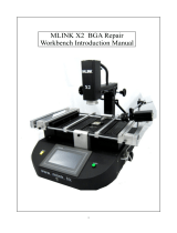
2. Product Picture
LCD Display Screen
Power Switch
TOP Heater
PCB Fixture
Fixture Fixing Knob
Keyboard
3. The unit is supplied with:
Please check whether the following parts are included and intact.
* Main Unit BGA2025
* Sirocco nozzle
* PC and LCD Display Screen
* BGA2025 Operation Manual
* K-type sensors
* Video line
* BGA Toolbox
Note: The parts will be packed according to the packing list. If you don’t purchase the optional part, it will not
be in the package. If any part stated above is missed out, please contact with our company or agents
immediately.
Page 2

QUICK2025 manual operation
4. Safety Instructions
Note: For the safety of the system and operator, please read this manual carefully before operating the unit.
Please note that the unit is suitable for soldering and de-soldering of electronic components.
Note: Top and bottom infrared heater and sirocco nozzle will be very hot during working, so explosive and
combustible object or gas and solvent is strictly prohibited in working areas, also please don’ touch the
hot surface parts.
This equipment must be grounding when using.
Note: The laser alignment device includes a secondary laser device, so don’t see the laser bean directly.
Note: When the system in trouble and needs maintenance, it should be maintained by an experienced and
authorized technician or expert, or contact with service agent and factory.
The unit with dangerous voltage! The inexperienced maintenance is dangerous for the operators.
5. Specifications and Technical Parameters
5.1 Specification
1. General Power 3500W (Max)
2. Power of Bottom Heater 1800W (4*450W Infrared ceramic heating tube)
3. Power of Top Heater 960W (8*120W)
2~8µm Approx
4. Power of Bottom Sirocco Heater 700W
5. Adjusting Range of Top Heater 20~60mm
6. Preheating size of bottom radiate board 450mm*648mm
7. Maximal PCB size 500mm*600mm
Minimal BGA size 2*2mm
Maximal chip size 60*60mm
8. bottom cooling fan
9. LCD Display Screen Size: 100*75 (mm) 16×2 character
10. Communication Standard RS-232C (Connect with PC)
11.Infrared Temperature sensor 0~300℃ (temperature testing range)
12.Outside K Type Sensor 5pieces
13. Camera 12V/300mA
Horizontal resolution: 480 TV lines
PAL format (composite)
Page 3

QUICK2025 manual operation
Page 4
14.LED lighting White LED (lower side), Red LED (upper side) (with adjustable brightness)
15. Paste Precision ±0.025mm
16.Paste force 1.5N
17.Power Supply 220V/230V AC、 50/60HZ、 3500
5.2 Technical Parameter
Main Interface:
TL: Melting temperature of the solder
T1: starting temperature of heat preservation in the reflow soldering process
T2: ending temperature of heat preservation in the reflow soldering process
T3: Peak value temperature of the soldering and de-soldering process
T0: Valve temperature: The least temperature of the top heater in top heater heating process. T0<TB1
TIR:The setting temperature of bottom heating tubes
TB: The real temperature of bottom heater
TC: The real time temperature of Top Heater
TB1:The setting temperature of bottom heater before T2
TB2:The setting temperature of bottom heater after T2
KTB:The real temperature of bottom sirocco heater
KIR:The real temperature of bottom Infrared heater
IRT:The real temperature of IR sensor inspecting
S0: Heating time from T0 to T1
S1: Heating time from T1 to T2
S2: Heating time from T2 to T 3
S3: Heating preservation time of T3
TOS:select the using sensor (to select between IR and KT1-KT5)
TYP:select solder flow or de-solder flow( DESO, SOLD)
CUF:select the current process (0-9 ten processes)
TOH:Top heater in working mode or not
BOH:Bottom sirocco heater in working mode or not
IRO:Outside parts of the Bottom Infrared heating tube in heating state or not
IRI:Inside parts of the bottom Infrared heating tube in heating state or not
BUM:Pump is in working mode or not
FAN:Top cooling fan in working mode or not
HED:the position of the top heater(UP-DOWN-UNKN)
ALG:the position of the contraposition arm(IN-OUT-UNKN)
SUC:the position of the nozzle(UP-DOWN-UNKN)
TIM:Showing the count down time
CST:Starting temperature of one step in the whole process
CSE:Ending temperature of one step in the whole process

QUICK2025 manual operation
Page 5
System Interface
PASSWORD: System password
SOUND: alarming switch of the host(ON---with alarm sound OFF—without alarm sound)
ADDED IR: heating switch of the outside group of the bottom Infrared heating tubes(ON---switch is on;
OFF---switch is off)
COM BAUD: Default baud is19200
Data Interface
Data interface has data of the ten working modes which parameter can be changed according to demands.
Calibrating set as follows. Reference data in the column“CAL”means the parameters whether calibrating or not.
If “CAL” is on, the parameter has been calibrated and is saved in the process. Change “ON” to “OFF” if user
wants to cancel the calibration.
QUICK BGA 2025 has ten working modes which parameter can be changed according to demands. Calibrating
set as follows.
T0 S0 T1 S1 T2 S2 T3 S3 TL TIR TB1 TB2
BF
A
SEN TYP
CA
L
0 90 40 145 50 160 55 200 30 183 150 140 160 9 0 0 0
1 90 55 145 50 155 40 200 20 183 165 130 150 9 0 1 0
2 90 40 140 50 150 50 200 15 183 160 125 145 9 0 0 0
3 90 45 140 60 155 40 200 20 183 160 135 150 9 0 1 0
4 80 55 145 65 155 45 200 25 183 170 140 160 9 0 0 0
5 80 60 165 45 175 45 230 25 217 170 150 170 9 0 1 0
6 90 60 160 45 170 40 230 20 217 170 160 180 9 0 0 0
7 90 60 165 40 175 45 230 25 217 170 160 180 9 0 1 0
8 90 60 160 45 175 40 230 20 217 170 170 180 9 0 0 0
9 90 60 165 40 170 40 230 20 217 170 150 170 9 0 1 0
Note:typ:0—sold, 1—deso sen:0—ir cal:0—no cal Time unit:“S” Temperature unit:“℃”
6、Install and Connecting of the Equipment
6.1 check the package of the equipment
* Check the package of the equipment is good or not.
* Take out the QUICK BGA 2025 rework system from the package and place it on the solid working desk.
* Check every unit is good or not. If not, please replace the unit from our company or agents in time.

QUICK2025 manual operation
6.2 Install the LCD
1. Take out the LCD carefully from the package, back out the base of the LCD and then unscrew the four fixed
screws.
2. Install the fixing board to the LCD and screw down the fixed screws.
3. Screw down the fixed knob in the left and lock screw in the right of the fixing board and install the fixing
board on the bracket and then screw down the knob and screw.
4. Connect the plug of the RPC to the socket at the bottom of the braket.
5. If user wants to adjust the height of the LCD , please unscrew the fixed knob and lock screw to adjust the
LCD to suitable height and then screw down the fixed knob and lock screw.
Fixed screw
Lock screw
LCD
Fixed knob
6.3 Connect the Equipment
* Check the using power supply whether is the same with the rating voltage value in the specification
scutcheon.
* Check the switches of the entire units are turn off or not.
* Connect the power cord to the power socket.
* Connect the RS-232 cord to the RS-232 socket in PC if you use the BGA software.
* Connect the video line of the external monitor to the VIDEO-OUT socket.
* Connect the K type sensors (optional) to the external sensor’s socket in the front.
Video input Video output
Interface RS-232
Power cord
Fuse socket
Page 6

QUICK2025 manual operation
Page 7
To the monitor interface o
r
the video interface
To the interface RS232
of the PC
To the powe
r
supply socket
Turn on the switch of the power supply after connecting all the units and cords.
7、Parts Instruction
* SENSOR
The system has five K type sensors checking the temperature of the point in the PCB, such as the temperature of
BGA surface, bottom temperature of the PCB, real temperature of the tin ball. And these values can show on the
LCD. Besides, users can select the sensors during KT1-KT5 by “TOS”.
The system is a closed loop temperature controlling. Testing the temperature of BGA surface with infrared
temperature sensor. Besides bottom sirocco and infrared heater test the temperatures with other K sensors.
* TOP HEATER
The power of the top infrared heater is controlled to satisfy the different needs and only one of it is normally
opening and others are controlled by the three switches on the faceplate.
One group of the top infrared heater near the inside is usually opening without switch controlling and the power
is 240W. When enhancing the power of the top heater, set the switch of the “TOP HEATER” as “ON”. The
power enhances 240W every opening one group heating tubes.
K type sensors
Controlling switches of top heater

QUICK2025 manual operation
* DISPLAY WINDOW
LCD display window shows all the informatio
n
and data of the system. Users can see clearl
y
p
arameters in the all interfaces and the positio
n
information of the every part. Display the
relevant information with the process running.
Display window
Air blow meter
* APERTURE ADJUSTING
The aperture system of the top infrared heater is adjustive from 20mm*60mm to 60mm*60mm by one
adjustment knob. Unscrew the knob before adjusting, and adjust the window size that you want , then screw
down the knob. The scale “2” on the housing means 20mm and “3’ means 30mm, other scale is similar. For
example, if you want to adjust it to 50×50 (mm), adjust one knob to the scale of “5” and screw down the
knob.
Page 8
Aperture adjusting knob

QUICK2025 manual operation
Note: Adjusting the aperture system can protect the adjacent components on the PCB from being heated.
But when the aperture system is adjusted to too small size, the top heater will become very hot
when working continuously. So it’s necessary to increase the size appropriately to avoid cutting off
the life of the heater.
* Bottom Preheated Board and PCB Fixture
Bottom preheated board has infrared heater and sirocco heater. Sirocco part heaters controlled by the
temperature curve is to the PCB of the BGA bottom and infrared heater controlling the preheated temperature
is to the whole PCB to prevent part transfiguration of PCB. According to different position of the BGA on the
PCB, move the infrared heater in X-axis to ensure even heating of the PCB.
N
ozzle of the sirocco heate
r
PCB fixture Bottom infrared heater
* Bottom Preheater
The size of the bottom infrared preheater is 450mm*650mm and one group infrared heating tubes near outside
of it is controlled by the switch. User can open the heating tubes according to the size of the PCB and other
technics need. It is setting the parameter “ADDED IR” in the SYSTEM interface to control the switch state
(“on ”means heating and “off ”means do not heating)
For not lowering the bottom temperature of the BGA an
d
the de-soldering effect and reducing the preheate
d
temperature of the whole PCB, bottom sirocco heater is to
the PCB board of the BGA bottom.
When top-cooling fan starts to work, bottom sirocco
nozzle blows cool air at the same time for cooling the
PCB of the BGA bottom and more quicken.
Top cooling fan
Bottom sirocco nozzle
Page 9

QUICK2025 manual operation
* PCB Fixture
● Movable PCB fixture is able to fix PCB with different size. It has four lock knobs and two micro-adjusting
knobs. Two PCB lock knobs are used for locking PCB Fixed Bar to prevent it from moving the PCB. The
other two Fixture Lock Knob is used for locking orbit to prevent fixture from moving. The two
micro-adjustable knobs are used for precise adjusting when the elements align.
● Unscrew PCB Lock Knobs and push the Slide Block by hand to open the PCB Fixed Bar, make the distance
accord with PCB size. Fix PCB between them and screw down PCB Lock Knobs after adjusting position.
PCB can move forwards and backwards between Fixed Bars. If you want to lock PCB Fixture, please screw
down Fixture Lock Knobs.
● when the elements precise align, screw down the lock knobs before micro-adjusting. Turn “micro-adjusting
knob one” for moving the PCB fixture to left or right. The PCB fixture to right when turning clockwise and
to left when turning anticlockwise. Turn “micro-adjusting knob two” for moving the PCB fixture to front or
back. The PCB fixture moves to front when turning clockwise and to back when turning anticlockwise.
Micro-adjusting knob
Lock knob
●Fixing Anomalistic PCB
Fix anomalistic PCB with anomalistic knightheads an
d
bottom fixtures for preventing subside.
* Keyboard Instruction
The keyboard can control all the data setting and modifying flows. The keys in the middle of the keyboard
are used for setting parameters and the keys in the right are used for adjusting the light of the camera and
zooming the image. The keys in the left are function keys to control the start and exit of the process.
Page 10

QUICK2025 manual operation
Keyboard
A、 control the cursor moving to left or right and data modifying with UP、DOWN、LEFT、RIGHT key at any
interface
B、 Function of the “SET” key is confirming the input information and function of the “SAVE” key is saving
the information and than exiting the process.
C、 BEGIN key:Make the system into the reflow de-solder process or reflow solder process in the waiting
state
D、 EXIT key:Exit the current running process after pressing it and back to the starting state after pressing it again
E、 T-H(↑)and T-H(↓) key: Control the top heater moving up and down by manual
F、 SUCKER(↑)and SUCKER(↓)key: Control the nozzle moving up and down
G、 CAM-CON key: controlling the position of the aligning arm inside or outside
H、 SUCK key:Make the system into the chip sucking state and suck the chip
I、 PASTE key: controlling the chip placing
J、 FAN-CON key: controlling the cooling fan. Cooling fan starts to work after pressing the key and bottom
sirocco nozzle blows cool air. Cooling fan stops work and does not blow cool air when
pressing it again.
K、 “FOCUS+”and “FOCUS-”key: For camera focusing
L、 “ZOOM+” and “ZOOM-” key: Zooming the image
M、 “RED+” and “RED-”key: Adjusting the brightness of the top red light
N、 “WHITE+” and “WHITE-” key: Adjusting the brightness of the bottom white light
O、 CA L key:In the process of reflow de-solder or reflow solder, pressing the key when the temperature
between T2 and T3, make TC is equal to TL to multiply the coefficient by current
temperature. It is calibrating the parameter of TEL and saving it (in the hole of CAL).
Note: It must be in the DATA interface to cancel the calibrating. Setting the “CAL” parameter as “OFF”
to cancel the calibrating quotiety back to initial state. In initial state, please do not press the key
CAL that will affect the calibrating of the other temperatures. If pressing the key CAL not carefully,
please press the key SAVE on time exiting the process. This is different to the other rework system
QUICK2005 and QUICK2015.
* Aligning arm instruction
Aligning arm is used in the element alignment. In the aligning arm, there is a camera which transmitting the
information by video cord and then displaying the image about the soldering point in the PCB and element
pins below the nozzle. Users can observe element alignment by adjusting function keys.
Page 11

QUICK2025 manual operation
● Aligning arm is controlled by the “CAM-CON”
key. Pressing “CAM-CON” key, when the aligning
arm is in side, it will move automatically from inne
r
to outer and stop in one line with the top heater, an
d
when the aligning arm is outside, it will do the
opposite action to the initial state. But the aligning
arm does not act when pressing it until the top
heater up to certain height.
● Aligning arm is outside when the camera in using
state and the light of the camera is adjustable. Use
r
can get a clear image by lighting, focusing an
d
zooming and the aligning operation is easy an
d
convenient by micro adjusting.
Aligning
arm inside
Aligning
arm outside
* Nozzle Instruction
● The nozzle will act during the process o
f
placing and sucking the chip, SUCKER(↑)
and SUCKER(↓)keys control the nozzle
moving upwards and downwards.
● Press “SUCK” key to the state of the chip
sucking and the nozzle will suck the chip
automatically.
● Press “PASTE” key to the state of the chip
pasting and the nozzle will paste the chip
automatically.
● Element adjusting knob is in the middle. Tur
n
it when optics alignment to make the BG
A
sucked by the nozzle turning until the
stannum ballpoint in the BGA is
superposable with the cuprum point in the
PCB. During the process, up and dow
n
micro-adjusting knobs and left and righ
t
micro-adjusting knobs work in together fo
r
precise alignment.
Aligning knob
Heating arm
N
ozzle
Page 12

QUICK2025 manual operation
8、Parameters Setting
Interface Setting
A.MAIN (current process setting)
B. SYSTEM (system setting)
C.DATA (parameters setting)
A、 MAIN Current Process Setting(with keyboard)
It is necessary and must to adjust the parameters when de-solder firstly PCB and BGA. Operation steps are
as follows.
For example: setting the temperature of TEO is 95℃(former temperature is 80℃)
TC and TB show room temperatures in initial state. Press “SET” key to select the “T0:080℃ ”and then
press “SET” key again into the setting state. Cursor is in the 1’s digit of the selecting item.
Pressing “UP” or “DOWN” key to change the value of the 1’s digit as“5”, and then pressing “LEFT” key to
make the cursor move forwards one digit. Pressing “UP” or “DOWN” key again to change the ten’s digit “9”.
Press “SAVE” key to save the data. Press the “SAVE” again to exit the parameter setting state if only need to
set the “TO” and then press “RIGHT” key to the next parameter setting.
Page 13

QUICK2025 manual operation
B、System Setting:
System setting includes password setting, alarming setting, setting controlling switch state of out side parts of
the bottom infrared tubes, baud setting.
1) Press “RIGHT” key to the system setting interface in the MAIN interface.
2) Press “SET” key to select “PASSWORD” item. Press “SET” key again to setting value of the
“PASSWORD”. The data setting refers to the example one.
* Initial password is “000”and omnipotent password is “159”. Users can input omnipotent password “159” if
forgetting the setting password and then the system is back to initial password “000”.
* If user needs to modify the password, inputting the new password again with the above method. It will
display: Saving Password when successfully modify!
Note: it must input the right password if user wants to modify the setting parameters, otherwise only
can consult the system, not have the authority to modify the parameters.
3) Press “SAVE” key to save the data and press “DOWN” key to setting the alarm parameter. If setting
“SOUND” as “ON”, it will alarm when the temperature up to the TL.
4) Press “SAVE” key to save the data and press “DOWN” key to setting controlling switch state of the out side
parts of the infrared heating tubes. If setting “ADDED IR” as “ON”, it means the out side parts of the infrared
heating tubes are heating when the bottom heating. Setting method as above.
Page 14

QUICK2025 manual operation
C、Parameter Setting of the DATA Interface
Press “SET” key and select the “DATA”, and then press “SET” again to setting the parameters. Now the cursor
is on the selecting item and the method of the setting the parameters as the example one. “DATA” interface will
show the ten processes in the host machine. Of course, user can modify it by oneself as needing. The ten
processes all have password protection and authority setting to ensure the reliable technics
Note: It must be in the DATA interface to cancel the calibrating. Setting the “CAL” parameter as “OFF”
to cancel the calibrating quotiety back to initial state.
C-1.Modify Parameter of working flow
1.If it is necessary to modify parameters of some processes, first you must select the certain process and then
modify its parameters (modify method as above).
2. The modification of parameter must accord with the following technics graph.
Tb
TB2
TB1
TC
Tir
TS3TS2
℃
TS1
表示Tb
表示TC
T1
T2
TL
T3
Tb=T0
Page 15

QUICK2025 manual operation
Page 16
The soldering technics is decided by T0、TB1、TB2、T1、T2、T3、S1、S2 and S3. It describes the temperature
graph during the period of the system working. TL means Melting temperature of solder and the range between
T2 and T3.
T0
T0 is the valve temperature of the bottom heater required by the top heater heating. Also it is the first
temperature of this technics process. When the working flow begins, the bottom heater starts to heat up and the
top heater begins to heat up after the temperature up to T0.
TB1、TB2
TB1:The setting temperature of the bottom before the T2
TB2:The setting temperature of the bottom after the T2
T1
T1 is the heat preservation starting temperature of reflow soldering. It is also the second temperature of this
technics process. The temperature rises to T1 with a proper speed of the electronic elements permitting. Use the
UP, DOWN, RIGHT, LEFT, RIGHT, SET and SAVE key to set the values of T1 when modifying the
parameters.
T2
It is the temperature when finishing the heat preservation of reflow soldering. The pre-heating temperature rises
to T2 when to the time S1. During this time, PCB and component pre-heating is finished and the solder is
activated. Use the
UP, DOWN, RIGHT, LEFT, RIGHT, SET and SAVE key to set the values of T2 when
modifying the parameters.
T3
It is the peak value temperature of reflow soldering. When the temperature reaches T2, the temperature equably
rises to T3 with a definite raising speed. The soldering or de-soldering will be finished when the temperature
reaches to the peak value and performs the next step. Use the
UP, DOWN, RIGHT, LEFT, RIGHT, SET and
SAVE key to set the values of T3 when modifying the parameters.
TL
Melting temperature of solder. At this temperature, the solder starts to melt down and turn into liquid.
During the soldering and de-soldering, users can press CAL Key to calibrate the value of TL when the solder do
not turn into liquid or do not turn into liquid on time. Use the
UP, DOWN, RIGHT, LEFT, RIGHT, SET and
SAVE key to set the values of TL when modifying the parameters.
S1
Heating time rises from T1 to T2. User can set the value in the range of 0~300s.
S2
Heating time rises from T2 to T3. User can set the value in the range of 0~300s.
S3
Prolonged heating time (heat preservation time) after the temperature reach T3, and user can also set the value

QUICK2025 manual operation
in the range of 0~300s.
TIR、 KTB
TIR:the setting heating temperature of the bottom heating tubes;
KTB:Real-time temperature of bottom sirocco heating, correspond to TB 底部热风实际温度,相当于 TB
KIR、 IRT
KIR:Real-time temperature of bottom infrared heating
IRT:Real-time detecting temperature of the infrared sensor
TB、 TC
TB:Real-time temperature of bottom infrared heating
TC:Real-time temperature of top heating
TOS
It is used for choosing the system’s sensor type between IR and KT1-KT5. Besides system’s non-touch infrared
sensor (IR), users can also choose K type sensor used for measuring temperature. The signal of chosen sensor
will be displayed and used for process controlling. Use the
UP, DOWN, RIGHT, LEFT, RIGHT, SET and
SAVE key to set the values of TEL when modifying the parameters.
Password
It is used for setting password. It is designed for preventing the equipment unnecessary or non-authorized
change. When it is set to “000”, the password protecting is useless. The password is used for all flows and it can
be useful and useless in each flow. The system requires inputting correct password before any change.
Using of password refer to A item.
9、Operating Technics Instruction
Note: Top and Bottom Heater will be very hot during working, so please don’ touch the hot surface of
the parts.
9.1 Soldering Technics (System’s power supply is on)
1. Turn on power switch of each part.
2. Move PCB Fixture bracket with PCB above the Bottom heater and make the soldered component on the
Page 17

QUICK2025 manual operation
Page 18
PCB between Top heater and Bottom heater (the soldered elements have been placed on the PCB board by
PL system). The position of the soldered BGA must be corresponding with the position of the sirocco
nozzles.
3. Adjust aperture system for getting a proper window size.
4. Select parameters with keyboard. (Refer to Parameters setting)
A. Select the required flow, if need to modify the parameter, input the password before performing
relevant operation.
B. Select “solder” working mode.
C. No change in communication speed, and press “SAVE” button to save and exit to MAIN surface.
D. System starts working after pressing “BEGIN”, running the select flow
5. LCD will display series of setting temperatures and the current temperature of TB and TC during working,
and indicate when it reaches T1, T2, T3 and TL. S1, S2 and S3 are counted down and user can know about
the setting value clearly.
6. When the temperature reaches TL, there will be a sound signal (if setting alarming).
7. When the temperature reaches T3, the sound signal changes to a briefness sound and the system stops
heating for seconds of S3. After that, the system will not heat up anymore and exit the process
automatically and then the technical process is over.
8. The system can perform a series of function action during working.
A. After press BEGIN key, the top infrared heater move downward near to bottom.
B. After the system sounds unvaryingly, the top heater move upwards. Top cooling fan blows cooling air
and bottom sirocco nozzle stop blowing warm air to blow cooling air. The effect of cooling is better
when blowing cooling air simultaneously.
C. The top cooling fan and bottom sirocco stop blowing after 50 seconds, and the soldering technics is
over.
Note: The process of the De-soldering technics is same with the soldering technics besides selecting “DESO”
when setting the process parameter.
9.2 Aligning Technics
1. Turn on power switch of each part.
2. Press “CAM-CON” key and move the alignment arm to aligning position. The lights of up and down both
are on.
3. Place the component above the prism of the alignment arm.
4. Suck the chip automatically and back to aligning position after pressing “SUCK” key. Manual operation is
also convenient.
5. Check whether the image displayed on Monitor fitting user’s demand. Use keyboard to adjust it. Adjusting
refers to “Keyboard Instructions”.
6. Unscrew the PCB Fixing Knobs on the PCB Fixture to open PCB Clamp Bar. Fix the soldered PCB on the
PCB Fixture and adjust PCB’s position to the below of the aligning arm. Make the Monitor display the
image of soldering point, and make the images of soldering point and component in the same center point.
It is convenient for adjusting. After roughly adjusting, screw down Fixture Fixing Knob to lock PCB
Fixture to prevent it from sliding right and left.
7. Align the component with two Adjusting Knobs and two Micro-adjusting Knobs. Make the images of the
component soldering pins and the soldering point on PCB overlap. The image can be observed on the

QUICK2025 manual operation
monitor. Aligning adjustment refers to “Adjustment knobs” and “PCB Fixture”.
8. After alignment, aligning arm goes back to initial position when pressing “CAM-CON” key.
9. Paste the chip automatically when pressing “PASTE”. The aligning process is over and it’s the time to
solder.
2 3 4-1
4-2 4-3 4-4
7 8 9-1
9-2 9-3
9.3 Intelligent Processes Instruction
BGA2025 has three intelligent processes that can run many processes automatically to reduce the effects of
artificial operation.
(the pictures of the suck and paste process refer to 9.2)
1. Suck process
2. Paste process
3. Solder or de-solder process
Page 19
/