Page is loading ...

KPS 25sc
Krell Playback System
with Krell CAST Technology
Instructions for Use
Owner’s Reference

KPS 25sc
Krell Playback System
with Krell CAST
Technology
v 00.1
Krell Industries, Inc.
45 Connair Road
Orange, CT 06477-3650 USA
TEL 203-799-9954
FAX 203-891-2028
E-MAIL krell @ krellonline.com
WEBSITE http://www.krellonline.com
This product complies with the EMC directive (89/336/EEC) and the low-voltage directive (73/23/EEC).
WARNINGS
The KPS 25sc must be placed on a firm. level surface where it is not exposed to dripping or splashing.
Do not remove or bypass the ground pin on the end of the AC power cord. This can cause radio frequency
interference (RFI) to be introduced into your playback system. Operate the KPS 25sc only with the power
cord supplied.
The ventilation grids on the top of the KPS 25sc must be unobstructed at all times during operation. Do not
place flammable material on top of or beneath the component.
Turn off all systems’ power before connecting the KPS 25sc to any component. Make sure all cable termina-
tions are of the highest quality, free from frayed ends, short circuits, or cold solder joints.
Connecting non-CAST components to CAST inputs or outputs can damage your equipment and void your war-
ranty.
Do not attempt to change CAST cable terminations or CAST inputs or outputs to RCA or XLR connectors. It is
electrically impossible to convert CAST input or output connections for balanced or single-ended voltage oper-
ation.
THERE ARE NO USER SERVICEABLE PARTS INSIDE ANY KRELL PRODUCT.
Please contact your authorized Krell dealer, distributor, or Krell if you have any questions not addressed in
this reference manual.
(-~--~equipped
This product is manufactured in the United States of America. Krell* is a registered trademark of Krell Industries. Inc.. and is restricted for use by Krell
Industries. inc.. its subsidiaries, and authorized agents. Krell Playback System
TM
is a trademark of Krell Industries. Inc. Krell CAST is a patent pending of
Krell Industries, inc. Krell Link
TM
is a trademark of Krell Industries. Inc. [-~----~-I, HDCD
’~.
High Definition Compatible Digital* and Pacific Microsonics
TM
are either registered trademarks or trademarks of Pacific Microson~cs. Inc. in the United States and/or other countries. HDCD system manufactured
under license from Pacific Microsonics. Inc. This product is covered by one or more of the following: In the USA: 5.479.168. 5,638,074, 5.640.161.
5,808,574. 5,838,274, 5.854,600, 5.864,311, 5,872,531, and in Australia: 669114, Other patents pending. TosLink
TM
is a trademark of Toshiba
Corporation. All other trademarks and tradenames are registered to their respective companies.
©2000 by Kretl Industries, Inc. All rights reserved
P/N 303963

Contents
INTRODUCTION
DEFINITION OF TERMS
REVOLUTIONARY KRELL CAST
TECHNOLOGY
UNPACKING
PLACEMENT
AC Power Guidelines
QUICK START
Factory Default Settings
Input and Output Connections
Power On
To Play a Compact Disc
To Play Another Input Source
INSTALLING THE ACRYLIC COVER
Attaching the Acrylic Cover
Connecting the Flex Foil Cable
Adjusting the Cover Closing Speed
FRONT PANEL DESCRIPTION
BACK PANEL DESCRIPTION
REMOTE CONTROL DESCRIPTION
Battery Installation and Removal
Tabletop Remote Control
CONNECTING THE KPS 25sc
TO YOUR SYSTEM
Input and Output Connections
Power On
Factory Default Settings
KRELLLINK CONNECTIONS AND OPERATION
Connecting Components Through Krell Link
Krell Link Operation
TAPE INPUT AND OUTPUT
Page
1
1
3
4
4
4
5
5
5
6
6
6
9
9
10
10
12
15
18
18
18
22
22
23
23
24
24
24
25
Krell KPS 25sc iii

Contents,
continued
OPERATING YOUR KPS 25sc
To Play a Compact Disc
How to Write a Program
How to Create an A/B Loop
To Play Another Input Source
CUSTOMIZING CONFIGURATIONS
Change the Cover Operation Mode
Change the Shutter Operation Mode
Configuring for Theater Throughput
Amplifier Control Options
Adjust Menu Display Brightness
Assign Custom Names to Inputs
Change an Input’s Volume Trim
Change the Volume Control Sensitivity
Return All Settings to Factory Defaults
WARRANTY
RETURN AUTHORIZATION
PROCEDURE
SPECIFICATIONS
Page
26
26
26
27
27
27
27
28
28
29
30
30
31
31
31
32
33
Back Cover
Illustrations
FIGURE 1
FIGURE 2
FIGURE 3
FIGURE 4
FIGURE 5
Attaching the KPS 25sc Acrylic Cover
Connecting the KPS 25sc Flex Foil Cable
The KPS 25sc Front Panel
The KPS 25sc Back Panel
The KPS 25sc Tabletop
and Handheld Remote Controls
Page
7
8
11
14
17
iv Krell KPS 25sc

Introduction Definition of Terms
Thank you for your purchase of the KPS 25sc
Krell Playback System. The integrated design
of the KPS 25sc incorporates a compact disc
transport, a digital-to-analog processor, and a
high resolution preamplifier in one stand alone
unit. The compact disc transport design pro-
vides high position accuracy and eliminates
servo bounce and vibration. An acrylic cover
protects the integrity of the compact disc data.
The analog preamplifier features exceptionally
wide bandwidth with extremely low noise, and
the digital-to-analog converter makes the
KPS 25sc compatible with nearly every digital
audio source. Menu features allow customizing
of cover operation and color, menu display
brightness, input naming, and volume controls
for optimum functioning and ease of use.
The KPS 25sc provides a variety of main out-
puts: Krell CAST variable, balanced and single-
ended variable, and balanced and single-ended
fixed level for connecting to a second system.
The KPS .25sc can be connected to multi-room
switchers that operate whole-house music sys-
tems. The Theater Throughput feature simplifies
integration of an audio/video surround sound
processor with the KPS 25sc. Two remote con-
trol unitsma full-function tabletop remote with
direct access capability, and a simplified hand-
held remote~provide complete and convenient
remote control operation.
This owner’s reference manual contains impor-
tant information on placement, installation, and
operation of the KPS 25sc. Please read this
information carefully. A thorough understanding
of these details will help ensure satisfactory
operation and long life for your KPS 25sc and
related system components.
Following are the definitions of key terms used
in your owner’s reference manual.
CONFIGURATIONS
Krell Link
A method of synchronizing remote control oper-
ation for Krell systems that include multiple pre-
amplifiers, amplifiers, and associated compo-
nents. When Krell Link in/out connections are
used, the remote capabilities of the linked com-
ponents are controlled from one component,
called the control component. The linked com-
ponents respond to stand-by and operational
mode commands from the control component
via MIDI cables.
Theater Throughput
Theater Throughput is a Krell configuration
option that allows the signal from a surround
preamp/processor to pass through a Krell pre-
amplifier or integrated amplifier with no gain, for
integrated volume and balance management of
Krell home theater systems.
INPUT AND OUTPUT
CONNECTIONS
Balanced
A symmetrical input or output circuit that has
equal impedance from both input terminals to a
common ground reference point. The industry
standard for professional and sound recording
installations, balanced connections have 6 dB
more gain than single-ended connections and
allow the use of long interconnect cables.
Balanced connections are completely immune
to induced noise from the system or the envi-
ronment.
Krell KPS 25sc 1

Definition of Terms, continued
Krell Current Audio Signal Transmission
(CAST)
A proprietary Krell circuit technology for con-
necting analog components, in which the audio
waveform is transmitted between components
in the current rather than voltage domain. The
speed and bandwidth provided by Krell CAST
yields accurate, realistic music reproduction.
Krell components connected via CAST perform
as if they are all part of a single circuit.
Single-ended
A two-wire input or output circuit. Use care
when using single-ended connections as the
ground connection is made last and broken
first. Turn the system off prior to making or
breaking single-ended connections. Single-
ended connections are not recommended for
connections requiring long cable runs.
OPERATION
Off
When the power button on the front panel is
pressed and the blue power LED turns off, the
component is off.
Operational Mode
When the power button on the front panel is
pressed and the blue power LED illuminates,
the component is in the operational mode and
ready to play music.
Stand-by Mode
A low power consumption status that keeps the
audio and regulator circuits at idle. Krell recom-
mends leaving the component in the stand-by
mode when it is not playing music.
TECHNOLOGY
Krell Current Mode
A proprietary Krell circuit topology in which the
audio gain stages of a component operate in
the current rather than voltage domain. This
uniq ue technology provides the component with
exceptional speed and a wide bandwidth.
Krell HEAT
The Krell term HEAT, or High End Audio
Theater, ~s a design application incorporated
into Krell components to enhance multi-channel
home entertainment systems. A Krell HEAT sys-
tem is an integrated home theater system con-
sisting of a state-of-the-art Krell pre-amp
processor and matching amplifiers that repro-
duce two channel and multi-channel sources
with audiophile sound quality, placing the audi-
ence in the middle of a lifelike environment.
2
Krell KPS 25sc

Revolutionary Krell CAST
Technology
Current Audio Signal Transmission, termed
CAST, is a revolutionary method of connecting
analog audio components for unparalleled
sonic performance. Innovative engineering
combines the new Krell CAST circuitry with
existing Krell Current Mode technology to cre-
ate entire CAST systems that reproduce music
with incredible range, tonality, and precision.
Voltage Signal Transmission and the
Traditional Audio System
Traditionally, signal is transmitted in the voltage
domain between two components. In an audio
system, each com ponent is a discrete entity with
unique characteristics that act upon the musical
signal independently. Each component is
unaware of the other corn ponents in the system.
The cables that connect the components each
have their own electrical characteristics, which
affect the sonic presentation of the entire system.
CAST: A New Approach
CAST circuitry recognizes signal transmitted in
the current domain instead of the voltage
domain between each component. CAST trans-
mission unifies the individual components and
their interconnects into an electrically linked
whole. The sonic presentation of the entire sys-
tem remains intact.
CAST Basics
Here’s how a CAST audio system works.
Internally, each CAST source transfers, or
amplifies, current using Krell Current Mode cir-
cuitry. This current signal is then output using
CAST circuitry. When the signal is received by
a CAST input, Krell Current Mode circuitry
again takes over until the signal reaches the
loudspeaker. By maintaining the musical signal
in the current domain from beginning to end, an
entire CAST system behaves as if it is one com-
ponent. With CAST, anomalies of signal transmis-
sion between components are eliminated. Cable
impedances and their effects on the transmitted
signal are non-existent.
How CAST and Krell Current Mode Interact
While CAST is a new method of transferring the
musical signal between components, its orig n
stems from Krell Current Mode, the technology
developed to transfer the musical signal within
a component. CAST combined with Krell
Current Mode takes circuitry signal transmis-
sion to the next evolutionary level. In essence,
Krell Current Mode maintains the integrity of the
signal within the component and CAST pre-
serves the transmitted signal between compo-
nents. Together, CAST and Krell Current Mode
technologies unify separate Krell components
into a single global circuit.
CAST Cable Construction
A CAST system uses cables manufactured by
Krell and other manufacturers specially
licensed by Krell. Thin and flexible CAST cables
are constructed with the same build quality as
other Krell products and are aesthetically
matched to the components that Krell manufac-
tures. An all-metal body and locking connectors
with gold contacts are part of the standard no-
compromise specification developed for every
CAST cable made.
The Best Musical Performance
When you operate a CAST system, you will
hear significant improvements in every perfor-
mance area: speed, precision, dynamic range,
depth and width of the sound stage, transient
impact, tonal balance, harmonic distortion, and
mor.e. The goal for CAST is the same company
goal used for all Krell products. Krell strives for
the delivery of the best performance of a musi-
cal event for you, using the full expression of
technology to date.
Krell KPS 25sc

Unpacking Placement
1. Open the shipping box and remove the top
layer of foam. You see these items:
1 KPS 25sc
1 acrylic cover in velvet pouch
1 KPS 25sc tabletop remote control
1 KPS 25sc handheld remote control
2 packages of AAA-size 1.5 Volt batteries
(4 for tabletop remote control, 2 for
handheld remote control)
1 compact disc clamp
1 IEC connector (AC Power) cord
1 12 VDC (12 V trigger) cable
1
T-10 Torx wrench (for remote control
battery installation and removal)
1 cleaning kit for the acrylic cover
1 packet containing the owner’s
reference manual and the warranty
registration card
2. Carefully remove the unit and accessories
from the shipping box. Remove the foam
end caps and protective plastic wrap from
the KPS 25sc.
Notes
If any of these items are not included in the
shipping box, please contact your authorized
Krell dealer, distributor, or Krell for assistance.
Save all packing materials. If you ship your
KPS 25sc in the future, repack the unit in its
original packaging to prevent transit damage.
See Return Authorization Procedure, on
page 33, for more information.
Before you install the KPS 25sc into your sys-
tem, review the following guidelines to properly
place your component. This will facilitate a
clean, trouble-free installation. The KPS 25sc
does not require a special rack or cabinet for
installation. For the dimensions of the KPS 25sc,
see Specifications, on the back cover.
The KPS 25sc requires at least two inches (5
cm) of clearance on each side to provide for ade-
quate ventilation and at least 20 inches (50 cm)
of clearance above the component to allow for
the operation of the acrylic cover. Installations
inside cabinetry may need extra ventilation.
Note
The KPS 25sc incorporates an advanced sus-
pension system and does not require addition-
al mass coupling or isolation. You may experi-
ment with feet or cones as long as they are not
permanently affixed to the unit. Any unautho-
rized modifications to the unit or electronics will
void the warranty.
IMPORTANT
Do not attach enhancement accessories such
as rings, mats, or dampers to individual com-
pact discs. These accessories may interfere
with the compact disc transport, resulting in
erratic playback and/or poor sound.
AC POWER GUIDELINES
The KPS 25sc has superb regulation and does
not require a dedicated AC circuit. Avoid connec-
tions through extension cords or multiple AC
adapters. High quality 15 amp grounded AC
strips are acceptable. High quality AC line con-
ditioners or filters can be used if they are
grounded and meet or exceed the unit’s power
supply rating of 100 VA.
4
Krell KPS 25sc

Quick Start
To access the full array of available features for
the KPS 25sc, please read the entire KPS 25sc
owner’s reference manual. The abbreviated
procedures in this Quick Start section will allow
you to set up your KPS 25sc system quickly
and enjoy its basic features before you read the
entire manual. The following paragraphs outline
quick start procedures. For additional informa-
tion see Connecting the KPS 25sc to Your
System, on page 22.
FACTORY DEFAULT SETTINGS
The KPS 25sc is shipped with these default set-
tings:
The cover operation mode is set for auto. The
cover must be down for compact disc playback
to begin.
The shutter operation mode is shipped set for
auto. The cover automatically becomes opaque
when you play a compact disc and becomes
clear when playback stops.
All variable and fixed outputs are active.
IMPORTANT
You must install the acrylic cover before you
use your KPS 25sc. See Installing the Acrylic
Cover, on page 9.
INPUT AND OUTPUT
CONNECTIONS
See Figure 3 on page 11 and Figure 4 on page
14. Numbers in parentheses refer to figure
labels.
IMPORTANT
Connecting non-CAST components to CAST
inputs or outputs can damage your equipment
and void your warranty.
Do not attempt to change CAST cable termina-
tions or CAST inputs or outputs to RCA or XLR
connectors. It is electrically impossible to con-
vert CAST input or output connections for bal-
anced or single-ended voltage operation.
Please read the Warranty, on page 32, to
understand the warranty limitations of the
KPS 25sc.
1. Make sure all power sources and compo-
nents are off before connecting inputs and
outputs.
2. Neatly organize w~ring between the KPS 25sc
and the preamplifier and amplifier, and
between all other components. Separate AC
wires from audio cables to prevent hum and
other unwanted noises from being intro-
duced into the system.
3. Connect the Krell CAST cables from the left
and right Krell CAST 4-pin outputs (42)
the KPS 25sc back panel to your CAST-
enabled preamplifier or amplifier.
For balanced or s~ngle-ended operation,
connect the interconnect cables from either
the left and right fixed balanced (38), vari-
able balanced (39), fixed single-ended (40),
or variable single-ended (41) outputs on the
KPS 25sc back panel to the balanced or
single-ended inputs on your preamplifier or
amplifier. (The remaining outputs can be
connected to another preamplifier or ampli-
fier in a different system).
IMPORTANT
Use variable output terminals when the KPS 25sc
is connected directly to a Krell stereo power ampli-
fier or to a pair of Krell monaural power amplifiers
that do not have gain control. Using fixed outputs
can damage power amplifiers and loudspeakers.
Krell KPS 25sc 5

Quick Start, continued
INPUT AND OUTPUT CONNECTIONS, continued
4. Connect the cables from your source equip-
ment to the appropriate balanced (31), tape
(32) or single-ended (34, 35, 36) analog
inputs on the KPS 25sc back panel.
5. Connect the cables from your digital audio
or video source to the optics input (46)
coaxial digital input (47) on the KPS 25sc
back panel.
6. Connect the cables from the optics output
(43) or coaxial digital output (44) on
KPS 25sc back panel to send signals to a
digital recording device, external digital/ana-
log processor, or video source.
7. Connect the KPS 25sc to AC power: plug
" the AC power into the IEC connector (50)
the back panel, then plug and AC power
cord into the wall socket.
IMPORTANT
When switching between active sources, always
lower the volume to off or mute the output. This
ensures that the next source played does not
damage your system with a high output transient.
POWER ON
Power the KPS 25sc on using the back panel
power switch (48). The word KRELL momentarily
appears in the menu display (26). This shows the
KPS 25sc is initialized and ready for operation.
The KPS 25sc is now in the stand-by mode. The
red stand-by LED (12) illuminates.
TO PLAY A COMPACT DISC
1: After the KPS 25sc ~s initialized and in the
stand-by mode, use the power button (12)
key to switch the component to the opera-
tional mode. The blue power LED (13) illumi-
nates. The compact disc transport is active.
2. Gently raise the acrylic cover until it is upright
(approx. 90
°
angle).
3
Remove the Krell compact disc clamp and
place your compact disc on the transport.
4. Secure the compact disc with the compact
disc clamp (you must use this clamp since it
is part of the disc sensing mechanism).
5. Gently pull the acrylic cover forward until you
feel the damper mechanism resist slightly.
The damper mechanism is now engaged
and will automatically finish closing the
cover. Do not force the cover to close faster
than the damping mechanism allows.
6. Press the play button (4) or key to begin com-
pact disc playback (playback will not begin
unless cover is closed). The acrylic cover will
also turn opaque to protect compact disc data.
7. Use the level knob (25) or keys to adjust the
volume to the desired level.
8. Press the stop button (3) or key to end com-
pact disc playback.
TO PLAY ANOTHER INPUT
SOURCE
1. After the KPS 25sc is initialized and in the
stand-by mode, use the power button (12)
key to switch the KPS 25sc to the operational
mode. The blue power LED (13) illuminates.
2. Select the digital or analog input source using
the front panel button (14-19) or key. The red
LED above the source illuminates and the
source name appears in the menu display
(26).
3. Follow the input source operating directions.
6 Krel KPS 25sc

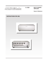
FIGURE 1 ATTACHING THE KPS 25sc ACRYLIC COVER
A.1
Push-pull pins fully closed
Pins are shipped fully closed and
must be returned to this position for
the acrylic cover to operate properly.
A Push-pull pins
B Acrylic cover p~ns
C Notches
D Flex foil cable
E
Flex foil receptacle
A.2
Push-pull pins fully extended
(Pin position is exaggerated for illustration purposes)
Pins are fully extended only during acrylic
cover installation. Do not try to close the
acrylic cover with the push-pull pins
extended.
Krell KPS 25sc 7

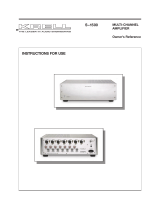
FIGURE 2 CONNE(;TING THE KPS 25sc FLEX FOIL CABLE
E
Front
Back
E.1
Open flex foil
receptacle
The open flex foil
receptacle sleeve is fully
extended, as shown. If
the flex foil receptacle
is not open, use your
fingers to grasp the
sleeve and gently slide
it toward the back of
the KPS 25sc, before
attempting to insert the
flex foil cable.
D
~
The closed flex foil
~,~j~
receptacle.
The flex foil cable
should be curved
E.2
Align the tip of the flex
foil cable parallel to the
open flex foil receptacle
and gently feed the flex
foil cable into the open
flex foil receptacle until
the cable touches the
rear of the receptacle.
slightly but not crimped.
Close the flex foil recep-
tacle by sliding the
sleeve toward the front
of the KPS 25sc.
Krell KPS 25sc

Installing the Acrylic Cover
See Figure 1 on page 7 and Figure 2 on page 8
The KPS 25sc is equipped with an acrylic cover
that protects the integrity of compact disc data.
The user can customize the cover’s operation
and closing speed. See Customizing Configu-
rations, on page 27.
IMPORTANTmUSER PRECAUTION
Please read the following USER PRECAU-
TION before attempting to install the acrylic
cover.
The KPS 25sc acrylic cover is mechanically
damped to ensure smooth operation while clos-
ing. If you force the cover to close, you will dam-
age the cover and the damping assembly.
During operation, please do not force the cover
to close faster than the damping mechanism
allows.
ATTACHING THE ACRYLIC COVER
To attach the acrylic cover, follow the steps
described below and further illustrated in Figure
1 on page 7.
IMPORTANT
Attach the acrylic cover before connecting the
flex foil cable.
1.
Carefully remove the acrylic cover from the
velvet pouch and place the cover on a soft
surface.
2. Locate the two push-pull pins (A) just above
the KPS 25sc back panel. These pins are
shipped in the fully closed position (see
detail A.1). Pull the pins out until they are
fully extended, as shown in detail A.2.
3.
Locate the pins (B) at the base of the acrylic
cover and the notches (C) on top of the
KPS 25sc, above the push-pull pins (A).
4. With the acrylic cover perpendicular to the
KPS 25sc, align the acrylic cover pins (B)
with the notches (C) in the top of the
KPS 25sc.
5. Gently lower the acrylic cover into the
notches (C), positioning the acrylic cover
pins (B) in the notches (C) in the top of
KPS 25sc.
IMPORTANT
Make sure that the flex foil cable (D) attached
to the cover is not pinched or crimped as you
position and secure the acrylic cover.
6.
Push the push-pull pins (A) back in
secure the cover. See detail A.1 for correct
pin position.
IMPORTANT
The KPS 25sc is shipped from the factory with
the cover push-pull pins fully closed. Push-pull
pins are fully extended only during cover instal-
lation and must be closed when operating the
acrylic cover.
Do not try to close the acrylic cover at this time.
Connect the flex foil cable first.
You can customize the acrylic cover to be clear
or opaque, and to close at varying speeds. See
Adjusting the Cover Closing Speed, on page
10, and Customizing Configurations, on
page 27.
Krell KPS 25sc

Installing the Acrylic Cover, continued
CONNECTING THE FLEX FOIL
CABLE
To connect the flex foil cable, follow the easy
steps described below and illustrated in Figure
2 on page 8.
IMPOFITANT
Do not crimp the flex foil cable, either manually
or with pliers or other tools. Crimping will dam-
age the flex foil cable and make ff inoperable.
Use care when inserting the flex foil cable. Its
edges can be sharp.
1.
Locate the flex foil cable (D) attached to the
acrylic cover and the flex foil receptacle (E)
on top of the KPS 25sc. Make sure the flex
foil receptacle is open (see detail E.1).
2. Using your fingers, carefully align the flex
foil cable (D) so that its tip is parallel to the
open flex foil receptacle. Again using your
fingers, gently feed the flex foil cable (D)
into the flex foil receptacle until the cable
touches the rear of the receptacle (see
detail E.2).
3. Close the flex foil receptacle by sliding the
sleeve toward the front of tl~e KPS 25sc
(see detail E.3). There will be an audible
click when the flex foil cable locks into the
closed position (see detail E.4).
4. Recheck that the flex foil cable ~s curved but
not crimped.
The acrylic cover is now ready for operation.
ADJUSTING THE COVER
CLOSING SPEED
You can adjust the cover closing speed using
the lid damper adjust screw (37) on the back
panel. Adjustments can be made while the
cover is up or down.
To decrease speed, turn the screw
clockwise in 1/8 inch increments.
To increase speed, turn the screw coun-
terclockwise in 1/8 inch increments.
IMPORTANT
The lid damper adjust screw is very sensitive.
Always support the cover while adjusting the
screw to keep the cover from closing too fast.
10 Krell KPS 25sc

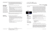
FIGURE 3 THE KPS .~5sc FR~ )NT PANEL
2 3 4
5
6
13 14 15 21 22 26 27
28
7 8 9 10 11 12
16 17 18 19 20 24 23 25 29 30
Compact Disc
Transport Functions
1 Compact Disc Display
2 Pause Button
3 Stop Button
4 Play Button
5 HDCD
®
LED
6 SYNC LED
7 Search Back Button
8 Search Forward Button
9 Track Back Button
10 Track Forward Button
11 Drive Off Button
12
Power Button and
Stand-by LED
13 Power LED
Digital Inputs
and LEDs
14 CD Button
15 AES Button
16 Optics1 Button
17 Optics2 Button
18 Coax1 Button
19 Coax2 Button
Analog Inputs
and LEDs
20 B-1 Button
21 S-1 Button
22 S-2 Button
23 S-3 Button
24 Tape Button
Volume Adjustment and
Menu Functions
25 Level Knob
26 Menu Display
27 Fixed Output Mute
Button and LED
28
Variable Output Mute
Button and LED
29 Menu Button and LED
30 Phase LED

Front Panel Description
See Figure 3 on page 11
The front panel of the KPS 25sc accesses
power on and off, compact disc functions, digi-
tal and analog input selections, volume and bal-
ance control, menu selection, and mute. The
displays show the status of com pact disc play-
back and volume, balance, and menu.
Compact Disc Transport Functions
1 Compact Disc Display
The compact disc transport display shows the
track number of the compact disc that is playing
as well as programming and other status
information.
2 Pause Button
Use this button to temporarily suspend play-
back of the compact disc track. To resume play-
ing the track at the point pause was engaged,
press the play button (4).
3 Stop Button
Use this button to stop compact disc playback.
4 Play Button
Use this button to activate playback from the
beginning of the compact disc, or to resume
playback after pause. For more information,
see Operating Your KPS 25sc, on page 26,
and Customizing Configurations, on page
27.
5 HDCD
®
LED
The HDCD
®
LED illuminates when a High
Definition Compatible Digital
®
disc is playing,
indicating that HDCD
®
decoding is functioning.
6 SYNC LED
The SYNC LED illuminates when the KPS 25sc
digital input selection has locked on to a valid
signal from the internal transport or an external
source component.
7 Search Back Button
Press and hold this button to scroll backward
through the current track,
8 Search Forward Button
Press and hold this button to scroll forward
through the current track.
9 Track Back Button
Use this button to select and begin playing the
track that precedes the current track,
10 Track Forward Button
Use this button to select and begin playing the
track that follows the current track.
11 Drive Off Button
Use this button to turn the compact disc trans-
port on and off.
12 Power Button and Stand-by LED
Use this button to switch the KPS 25sc between
the stand-by and the operational modes. The
red power stand-by LED illuminates when the
KPS 25sc is in the stand-by mode.
13 Power LED
The blue power LED illuminates when the
KPS 25sc is in the operational mode. The blue
power LED also flashes when any remote con-
trol key is pressed.
12
Krell KPS 25sc

Front Panel, continued
See Figure 3 on page 11
Digital Inputs and LEDs
The KPS 25sc is equipped with the following
digital inputs. The red LED above each button
illuminates when that input is selected.
14 CD Button
Use this button to select the internal compact
disc transport.
15 AES Button
Use this button to select the corresponding rear
panel input that ~s connected to an AES digital
source,
16 Optics1 Button
17 Optics2 Button
Use these buttons to select the corresponding
rear panel input that is connected to an EIAJ
fiber optic digital source.
18 Coax1 Button
19 Coax2 Button
Use these buttons to select the corresponding
rear panel input that is connected to a S/PDIF
coaxial source.
Analog Inputs and LEDs
The KPS 25sc is equipped with the following
analog inputs, The red LED above each button
illuminates when that input is selected.
20 B-1 Button
Use this button to select the corresponding rear
panel input that is connected to a balanced ana-
log source.
21 S-1 Button
22 S-2 Button
23 S-3 Button
Use these buttons to select the corresponding
rear panel input that is connected to a single-
ended analog source.
24 Tape Button
Use this button to select the corresponding rear
panel input that is connected to a tape source.
For instructions on using this function, see Tape
Input and Output, on page 25.
Volume Adjustment
and Menu Functions
25 Level Knob
Use this knob to increase or decrease system
volume level. Volume level is shown in the
menu display (26). The level control knob
also used, along with the menu control button
(29), to select menu functions to customize
KPS 25sc features. See Customizing Con-
figurations, on page 27.
26 Menu Display
The menu display shows volume level, balance
level, and menu function selection and status.
See Customizing Configurations, on page
27.
27 Fixed Output Mute Button and LED
Use this button to mute the fixed output. The
LED illuminates when the fixed output is muted.
28 Variable Output Mute Button and LED
Use this button to mute the variable output. The
LED illuminates when the variable output is
muted.
29 Menu Button and LED
Use the menu control button to access menu
functions for customizing the KPS 25sc. The
LED illuminates when the menu feature is acti-
vated. See Customizing Configurations, on
page 27.
30 Phase LED
The absolute phase LED illuminates when the
absolute polarity of the variable or CAST out-
puts is reversed.
Krell KPS 25sc 13

FIGURE 4 THE KPS 25sc BACK PANEL
31
32
33
37 38 39
42 43
44
45 48
49
50
34 35 36 40 41 46 47
51 52 53 54
Analog Inputs and Outputs
31 B-1 Left and Right Inputs
32 Tape n Left and Right
33 Tape Out Left and Right
34 S-1 Left and Right Inputs
35 S-2 Left and Right Inputs
36 S-3 Left and Right Inputs
Acrylic Cover
37 Lid Damper Adjust
Fixed and Variable Balanced Outputs
38 Fixed Left and Right
39 Variable Left and Right
Fixed and Variable Single-Ended Outputs
40 Fixed Left and Right
41 Variable Left and Right
Krell CAST Outputs
42 Krell CAST Outputs Left and Right
Digital Inputs and Outputs
43 Optics1 and Optics2 Outputs
44 Coax1 and Coax2 Outputs
45 AES Output and Input
46 Optics1 and Optics2 Inputs
47 Coax1 and Coax2 Inputs
Power
48 Back Panel Power Switch
49 Line Fuse
50 IEC Connector
Back Panel Remote Connections
51 Krell Link Out
52 Krell Link In
53 RC-5
54 12 VDC Out

Back Panel Description
See Figure 4 on page 14
The KPS 25sc back panel provides connections
for all inputs and outputs, power on/off, and
additional remote connections.
Analog Inputs and Outputs
31 B-1 Left and Right Inputs
The KPS 25sc is equipped with one pair of bal-
anced analog source inputs with XLR connec-
tors.
32 Tape In Left and Right
The KP$ 25sc is equipped with one pair of sin-
gle-ended tape source inputs with RCA con-
nectors.
33 Tape Out Left and Right
The KPS 25sc is equipped with one pair of sin-
gle-ended tape source outputs with RCA con-
nectors.
34 S-1 Left and Right Inputs
35 S-2 Left and Right Inputs
36 S-3 Left and Right Inputs
The KPS 25sc is equipped with three pairs of
single-ended analog source inputs with RCA
connectors.
Acrylic Cover
37 Lid Damper Adjust
Use this screw to adjust the speed at which the
acrylic cover closes. See Adjusting the Cover
Closing Speed, on page 10.
Fixed and Variable Balanced
Outputs
38 Fixed Left and Right
The KPS 25sc is equipped with one pair of fixed
level balanced outputs with XLR connectors.
39 Variable Left and Right
The KPS 25sc is equipped with one pair of vari-
able level balanced outputs with XLR connec-
tors.
IMPORTANT
When the KPS 25sc is connected directly to a
Krell stereo power ampfifier or a pair of Krell
monaural power amplifiers that do not have
galh control, use the variable output terminals
to ensure proper volume level control Using
fixed outputs could damage power amplifiers
and loudspeakers.
Fixed and Variable
Single-Ended Outputs
40 Fixed Left and Right
The KPS 25sc is equipped with one pair of fixed
level single-ended outputs with RCA connec-
tors.
41 Variable Left and Right
The KPS 25sc is equipped with one set of vari-
able level single-ended outputs with RCA con-
nectors.
Krell CAST Outputs
42 Krell CAST Outputs Left and Right
The KPS 25sc is equipped with one set of vari-
able level outputs, with 4-pin bayonet connec-
tors, for use with Krell CAST-equipped Full
Power Balanced 200c, 300c, and 600c Stereo
Amplifiers; and 250Mc, 350Mc, and 650Mc
Monaural Amplifiers or with the Krell Master
Reference Amplifiers.
Krell KPS 25sc 15

Back Panel, continued
See Figure 4 on page 14
Digital Inputs and Outputs
43 Optics1 and Optics2 Outputs
The KPS 25sc is equipped with two EIAJ fiber
optic digital outputs with TosLink connectors.
44 Coax1 and Coax2 Outputs
The KPS 25sc is equipped with two S/PDIF
coaxial digital outputs with RCA connectors.
45 AES Output and Input
The KPS 25sc is equipped with one AES digital
output and input with XLR connectors.
46 Optics1 and Optics2 Inputs
The KPS 25sc is equipped with two EIAJ fiber
optic digital inputs with TosLink connectors.
47 Coax1 and Coax2 Inputs
The KPS 25sc is equipped with two S/PDIF
coaxial digital inputs with RCA connectors.
Power
48 Back Panel Power Switch
Use the back panel power switch for the initial
KPS 25sc power on. For more information, see
Connecting the KPS 25sc to Your System,
on page 22.
49 Line Fuse
The 50/60 Hz line fuse protects the KPS 25sc
against short circuits from the external AC power.
Note
Replace fuses only with the fuse value speci-
fied on the back panel
50 IEC Connector
The connector is for use with the provided IEC
standard 15 amp AC power cord.
Back Panel Remote Connections
51 Krell Link Out
52 Krell Link In
The KPS 25sc is equipped with a Krell Link
communications output and input data port.
Krell Link allows synchronized remote power
on and off of other components with Krell Link,
such as Full Power Balanced amplifiers or
Master Reference Am plifiers.
53 RC-5
The KPS 25sc is equipped with an RC-5 input
that makes custom installation easy and secure
by accepting baseband RC-5 input commands
from hardwired remote controllers.
54 12 VDC Out
The KPS 25sc is equipped with an output that
sends 12 VDC power on/off (12 V trigger) sig-
nals to other Krel components and other
devices that incorporate a 12 V trigger. This
allows you to turn other components on or off,
or to and from stand-by, from the KPS 25sc.
When the KPS 25sc is switched between the
stand-by and operational modes, it sends a
signal from the 12 VDC Out that will switch
other components, allowing whole or parts of
systems to be easily coordinated.
Notes
The 12 VDC output power is limited to 30 ma.
Consult the owner’s reference of the components
used in a custom installation to take full advan-
tage of the remote capability of the KPS 25sc.
16
Krell KPS 25sc
/