Panasonic WVCL920_SERIES Operating instructions
- Category
- Security cameras
- Type
- Operating instructions

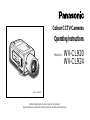
(Lens : option)
W
V
-
C
L
9
2
4
CL924
Before attempting to connect or operate this product,
please read these instructions carefully and save this manual for future use.
Model No. WV-CL920
WV-CL924
Colour CCTV Cameras
Operating Instructions

CAUTION
RISK OF ELECTRIC SHOCK
DO NOT OPEN
CAUTION:
TO REDUCE THE RISK OF ELECTRIC SHOCK,
DO NOT REMOVE COVER (OR BACK),
NO USER SERVICEABLE PARTS INSIDE.
REFER SERVICING TO QUALIFIED
SERVICE PERSONNEL.
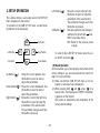
The lightning flash with arrowhead symbol,
within an equilateral triangle, is intended to
alert the user to the presence of uninsulated
"dangerous voltage" within the product's
enclosure that may be of sufficient magni-
tude to constitute a risk of electric shock to
persons.
The exclamation point within an equilateral
triangle is intended to alert the user to the
presence of important operating and mainte-
nance (servicing) instructions in the litera-
ture accompanying the appliance.
WARNING:
To reduce the risk of fire or electric shock, do not expose this appliance to rain or moisture.
The serial number of this product may be found on the top
of the unit.
You should note the serial number of this unit in the space
provided and retain this book as a permanent record of
your purchase to aid identification in the event of theft.
Model No.
Serial No.
ENGLISH VERSION
FOR YOUR SAFETY PLEASE READ THE FOLLOWING TEXT CARE-
FULLY.
WARNING: This apparatus must be earthed
IMPORTANT
The wires in this mains lead are coloured in accordance with the following
code.
Green-and-yellow: Earth
Blue: Neutral
Brown: Live
As the colours of the wire in the mains lead of this appliance may not
correspond with the coloured markings identifying the terminals in your
plug, proceed as follows.
The wire which is coloured green-and-yellow must be connected to
the terminal in the plug which is marked with the letter E or by the earth
symbol
I or coloured green or green-and-yellow.
The wire which is coloured blue must be connected to the terminal in
the plug which is marked with the letter N or coloured black.
The wire which is coloured brown must be connected to the terminal
in the plug which is marked with the letter L or coloured red.
For U.K.

-3-
CONTENTS
PREFACE ................................................................. 4
FEATURES ............................................................... 4
PRECAUTIONS ........................................................ 5
MAJOR OPERATING CONTROLS AND
THEIR FUNCTIONS ........................................... 6
CONNECTIONS ....................................................... 9
FOCUS OR FLANGE-BACK ADJUSTMENT ............ 13
INSTALLATION OF CAMERA .................................. 14
SETUP ...................................................................... 16
1. CAMERA SETUP MENU .................................... 16
2. SETUP OPERATION .......................................... 19
SETTING PROCEDURES ......................................... 21
PREVENTION OF BLOOMING AND SMEAR ........... 39
SPECIFICATIONS .................................................... 40
STANDARD ACCESSORIES .................................... 42
OPTIONAL ACCESSORIES ...................................... 43
Wij verklaren als enige aansprakelijke, dat het product waarop deze verk-
laring betrekking heeft, voldoet aan de volgende normen of andere nor-
matieve documenten, overeenkomstig de bepalingen van Richtlijnen
73/23/EEC en 89/336/EEC.
Vi erklærer os eneansvarlige for, at dette produkt, som denne deklaration
omhandler, er i overensstemmelse med standarder eller andre normative
dokumenter i følge bestemmelserne i direktivene 73/23/EEC og
89/336/EEC.
Vi deklarerar härmed värt fulla ansvar för att den produkt till vilken denna
deklaration hänvisar är i överensstämmelse med standarddokument, eller
andra normativa dokument som framstölls i EEC-direktiv nr. 73/23 och
89/336.
Ilmoitamme yksinomaisella vastuullamme, että tuote, jota tämä ilmoitus
koskee, noudattaa seuraavia standardeja tai muita ohjeellisia asiakirjoja,
jotka noudattavat direktiivien 73/23/EEC ja 89/336/EEC säädöksiä.
Vi erklærer oss alene ansvarlige for at produktet som denne erklæringen
gjelder for, er i overensstemmelse med følgende normer eller andre nor-
mgivende dokumenter som følger bestemmelsene i direktivene 73/23/
EEC og 89/336/EEC.
We declare under our sole responsibility that the product to which this
declaration relates is in conformity with the standards or other normative
documents following the provisions of Directives EEC/73/23 and
EEC/89/336.
Noi dichiariamo sotto nostra esclusiva responsabilità che il prodotto a cui
si riferisce la presente dichiarazione risulta conforme ai seguenti standard
o altri documenti normativi conformi alle disposizioni delle direttive
CEE/73/23 e CEE/89/336.
Wir erklären in alleiniger Verantwortung, daß das Produkt, auf das sich
diese Erklärung bezieht, mit der folgenden Normen oder normativen
Dokumenten übereinstimmt. Gemäß den Bestimmungen der Richtlinie
73/23/EEC und 89/336/EEC.
Nous déclarons sous notre seule responsabilité que le produit auquel se
référe cette déclaration est conforme aux normes ou autres documents
normatifs conformément aux dispositions de la directive 73/23/CEE et
89/336/CEE.
Nosotros declaramos bajo nuestra única responsabilidad que el producto
a que hace referencia esta declaración está conforme con las normas u
otros documentos normativos siguiendo las estipulaciones de las directi-
vas CEE/73/23 y CEE/89/336.

-4-
1. The following functions are built in.
(1) Auto Light Control (ALC)/Electronic Light
Control (ELC)
(2) Back Light Compensation (Auto: Factory pre-
set, Manual: Manual photometric measuring
area set)
(3) Various External Sync Functions, including
Gen-Lock
(4) Auto/Manual White Balance Function
(5) Electronic Shutter Function
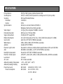
2. Signal-to-noise ratio of 50 dB
3. Minimum illumination of 0.3 lx (0.03 footcandle) with
F1.4 lenses (Colour mode)
4. Minimum illumination of 0.02 lx (0.002 footcandle)
with F1.4 lenses (Black and White mode)
5. 570 lines of horizontal resolution (Black and White
mode)
480 lines of horizontal resolution (Colour mode)
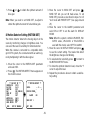
horizontal pixels (picture elements), and digital signal
processing LSI's. This model offers cutting-edge tech-
nology for advanced video surveillance.
PREFACE
Panasonic's WV-CL920 (WV-CL924) series digital
colour camera introduces a new level of high picture
quality and high resolution through the use of a 1/2-inch
frame interline transfer CCD image sensor having 762
FEATURES
6. High quality picture:
(a) 2H type vertical enhancer for greater picture
sharpness
(b) Chroma averaging circuit for better colour sig-
nal to noise ratio
(c) Minimum of aliasing on fine objects
(d) Expanded dynamic range by use of knee cir-
cuit
(e) Highlight aperture correction for greater picture
detail of bright objects
7. Ability to shoot indoor scenes with fixed iris lens by
use of Electronic Light Control (ELC) function.
8. Selectable electronic sensitivity enhancing modes
including: AUTO, MANUAL and OFF
9. Built in Digital Motion Detector
10. Auto Black/White mode enables the camera to
switch between C/L and B/W in response to input
lights.

-5-
1. Do not attempt to disassemble the camera.
To prevent electric shock, do not remove screws or
covers.
There are no user serviceable parts inside. Ask a
qualified service person for servicing.
2. Handle the camera with care.
Do not abuse the camera. Avoid striking, shaking,
etc. The camera could be damaged by improper
handling or storage.
3. Do not expose the camera to rain or moisture, or
try to operate it in wet areas.
Turn the power off immediately and ask a qualified
service person for servicing. Moisture can damage
the camera and also create the danger of electric
shock.
4. Do not use strong or abrasive detergents when
cleaning the camera body.
Use a dry cloth to clean the camera when dirty.
In case the dirt is hard to remove, use a mild deter-
gent and wipe gently. Afterwards, wipe off the
remained part of the detergent in it with a dry cloth.
5. Clean the CCD faceplate with care.
Do not clean the CCD with strong or abrasive deter-
gents. Use lens tissue or a cotton tipped applicator
and ethanol.
6. Never face the camera towards the sun.
Do not aim the camera at bright objects. Whether
the camera is in use or not, never aim it at the sun
or other extremely bright objects. Otherwise,
blooming or smear may be caused.
7. Do not operate the camera beyond the specified
temperature, humidity or power source ratings.
Use the camera under conditions where tempera-
ture is between –10°C - +50°C (14°F - 122°F), and
humidity is below 90 %. The input power source is
220 - 240 V AC 50 Hz for WV-CL920 and 12 V
DC/24 V AC for WV-CL924.
PRECAUTIONS

-6-
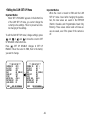
<WV-CL920>
<WV-CL924>
WV-
CL920
FB LOCK
FB LOCK
Hi-Z G/L 75
Ω
WV-
CL920
VIDEO OUT
GEN-LOCK
220-240V AC 50Hz
VIDEO OUT
GEN-LOCK
AC 24V
IN
DC 12V
IN
GND
2
1
re
!3
!2
!1
!2
!1
q w
!0 i
ytuo
!4
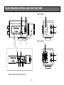
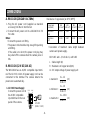
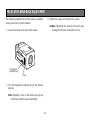
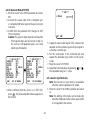
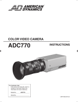
MAJOR OPERATING CONTROLS AND THEIR FUNCTIONS
Slide the panel to the left until it locks.

-7-
q Auto Iris Lens Connector
This connector is used to connect the auto iris lens
with a 4-pin male connector supplied as a standard
accessory (Part No. YFE4191J100).
w Flange-back Adjusting Ring (FB)
This ring is used to adjust the back focal length or
picture focus. Rotate this ring upward or downward
for a CS-mount lens. In case of using a C-mount
lens, adjust it with the C-mount adapter.
e Focus Fixing Screw (LOCK)
r Camera Mounting Screw Hole
This hole is used to mount the camera onto a
mounting bracket.
t Down Button ( )
This button is used to move the cursor downward. It
is also used to select items in the CAM SET UP
menu.
y Right Button ( )
This button is used to move the cursor to the right.
It is also used to select the mode and can be used
to adjust some levels.
u Left Button ( )
This button is used to move the cursor to the left. It
is also used to select the mode and can be used to
adjust some levels.
i Up Button ( )
This button is used to move the cursor upward. It is
also used to select items in the CAM SET UP menu.
o Set Button ( )
This button is used to activate an item selected in
the CAM SET UP menu.
!0 Gen-lock Termination Switch (Hi-Z, G/L 75Ω)
Set this switch to Hi-Z when a gen-lock video input
signal is looped through. In all other cases, set this
switch to 75 Ω.
!1 Gen-lock Input Connector (GEN-LOCK)
This connector is used to connect an external sys-
tem for synchronization.
!2 Video Output Connector (VIDEO OUT)
This connector is used to connect with the VIDEO
IN connector of the monitor.

-8-
!3 Power Cord Socket
This socket is used to connect the power cord
(supplied as a standard accessory).
!4 AC/DC Compatible Input Terminal
(DC 12V IN/AC 24V IN)
This terminal is for connecting the 12 V DC or 24 V
AC power supply cord.
Caution: Connect to 12 V DC (10.8 V-16 V) or 24 V
AC (19.5 V-28 V) class 2 power supply only.
Make sure to connect the grounding lead to the
GND terminal when the power is supplied from a
24 V AC power source.

-9-
Copper wire #24 #22 #20 #18
size (AWG) (0.22 mm
2
) (0.33 mm
2
) (0.52 mm
2
) (0.83 mm
2
)
Resistance 0.078 0.050 0.030 0.018
Ω/m
Resistance 0.026 0.017 0.010 0.006
Ω/ft
A. WV-CL920 (220-240 V AC 50Hz)
1. Plug the AC power cord (supplied as standard
accessory) into the AC Inlet Socket.
2. Connect the AC power cord to a 220-240 V AC 50
Hz outlet.
Notes:
• Connect the power cord firmly.
• The power cord should be long enough for panning
and tilting.
If the cable is too short, the power cord plug may
be pulled off the camera when the camera pans or
tilts.
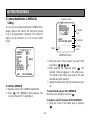
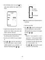
B. WV-CL924 (12 V DC/24 V AC)
The WV-CL924 has an AC/DC compatible input termi-
nal. The 12 V DC or 24 V AC power supply cord can be
connected to this terminal. The camera detects the
power source automatically.
1. 12 V DC Power Supply
Connect the power cord to
the AC/DC compatible
input terminal on the rear
panel of the camera.
Resistance of copper wire [at 20°C (68°F)]
AC 24V
IN
DC 12V
IN
1
2
GND
12 V DC
(10.8 V - 16 V)
• Calculation of maximum cable length between
camera and power supply.
10.8 V DC ≤ V
A – (R x 0.42 x L) ≤ 16 V DC
L : Cable length (m)
R : Resistance of copper wire (Ω/m)
V
A : DC output voltage of power supply unit
V
A – 12
L standard = (m)
0.42 x R
V
A – 16
L minimum = (m)
0.42 x R
V
A – 10.8
L maximum = (m)
0.42 x R
CONNECTIONS

-10-
2. 24 V AC Power Supply
Connect the power cable to the AC/DC compatible
input terminal on the rear panel of the camera.
Copper wire #24 #22 #20 #18
size (AWG) (0.22 mm
2
) (0.33 mm
2
) (0.52 mm
2
) (0.83 mm
2
)
Length (m) 95 150 255 425
of Cable
(Approx.) (ft) 314 495 842 1 403
Recommended wire gauge sizes for 24 V AC line.
AC 24V
IN
DC 12V
IN
1
2
GND
24 V AC, 50 Hz
(19.5 V - 28 V)
Video Cable
1. It is recommended to use a monitor whose resolu-
tion is at least equal to that of the camera.
2. The maximum extensible coaxial cable length
between the camera and the monitor is shown
below.
Type of RG-59/U RG-6/U RG-11/U RG-15/U
coaxial cable (3C-2V) (5C-2V) (7C-2V) (10C-2V)
Recommended (m) 250 500 600 800
maximum
cable length (ft) 825 1 650 1 980 2 640

-11-
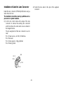
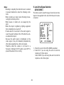
Installation of Auto Iris Lens Connector
Install the lens connector (YFE4191J100) when using a
video drive ALC lens.
The installation should be made by qualified service
personnel or system installers.
(1) Cut the iris control cable at the edge of the lens
connector to remove the existing lens connector
and then remove the outer cable cover as shown in
the diagram below.
The pin assignment of the lens connector is as fol-
lows:
Pin 1: Power source; +9 V DC, 50 mA Max.
Pin 2: Not used
Pin 3: Video signal; 1.3 V[p-p]/40 kΩ
Pin 4: Shield, ground
Pin 3
Pin 4
Pin 2
Rib
Pin 1
(2) Solder the lens cable to the pins of the supplied
connector.

-12-
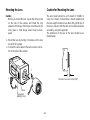
Caution for Mounting the Lens
The lens mount should be a CS-mount (1”-32UN). In
case of a C-mount, it should be a C-mount adapter and
the lens weight should be less than 450 g (0.99 lbs). If
the lens is heavier, both the lens and camera should be
secured by using the supporter.
The protrusion at the rear of the lens should be as
shown below:
CS-mount: Less than 4 mm (5/32”)
Screw
Flange-back
Adjusting Ring
w
q
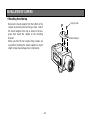
Mounting the Lens
Caution:
Before you mount the lens, loosen the fixing screw
on the side of the camera, and rotate this ring
upward until it stops. If the ring is not at the end, the
inner glass or CCD image sensor may be dam-
aged.
1. Mount the lens by turning it clockwise on the lens
mount of the camera.
2. Connect the lens cable to the auto iris lens connec-
tor on the side of the camera.

-13-
Screw
Flange-back
Adjusting Ring
The following adjustment should be made by qualified
service personnel or system installers.
1. Loosen the screw on the side of the camera.
2. Turn the flange-back adjusting ring to the desired
position.
Note: Adjusting a focus in the visible rays may be
soft-focused with the near-infrared light.
3. Tighten the screws on the side of the camera.
Caution: Tightening the screw by force will cause
damage to the screw or deviation of focus.
FOCUS OR FLANGE-BACK ADJUSTMENT

-14-
Fixing Screws
Mount Adapter
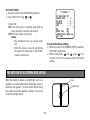
• Mounting from the top
Remove the mount adapter from the bottom of the
camera by removing the two fixing screws. Attach
the mount adapter to the top as shown in the dia-
gram, then mount the camera on the mounting
bracket.
Make sure that the two original fixing screws are
used when mounting the mount adapter as longer
length screws may damage inner components.
INSTALLATION OF CAMERA

-17-
White
Balance
ATW1 ATW2 AWC
Motion
Detector
Special
Menu
Display
Mode
CHROMA
GAIN
UP SIDE
DOWN
AP
GAIN
PEDESTAL
HUE
BW
BURST
(BW)
ON OFF
Camera
Resetting
Manual
Mask Area
Selection
Detection
Level
Adjustment
Lens Drive
Signal
Selection
AUTO1 AUTO2 ON OFF
Manual
Mask Area
Selection
DC VIDEO
-16-
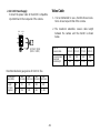
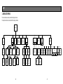
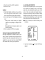
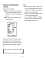
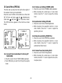
1. CAMERA SETUP MENU
This camera utilizes a user setup menu that is displayed on-screen.
The setup menu contains various items that form a tree type structure.
SETUP
Camera
ID
ON/OFF
Light
Control
ALC ELC
Shutter
Speed
CAM SETUP
AGC
ON(DNR-H)/
ON(DNR-L)/OFF
SYNC
INT LL
Camera
ID
Editing
Camera ID
Display
Position
PRESET OFF PRESET OFFPRESET ON
(Back Light
Compensation)
PRESET ON
(Back Light
Compensation)
EXT (VBS)
Automatic
Selection
EXT (VS)
Automatic
Selection
EXT (LL)
Manual
Selection
Manual
Mask Area
Selection
Manual
Level
Selection
Manual
Mask Area
Selection
Manual
Level
Selection
H.Phase
SC.Phase
Manual
Adjustment
H.Phase
Manual
Adjustment
V.Phase
Manual
Adjustment
Electronic
Sensitivity
Enhancement
OFF/AUTO/FIX

-18-
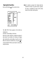
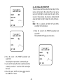
Note: If no button is pressed for 6 minutes while the
CAM SET UP menu or any other menu is opened,
the menu is automatically closed and the mode
returns to the normal camera picture.
** CAM SET UP **
CAMERA ID OFF
ALC/ELC ALC
SHUTTER OFF
AGC ON (DNR-H)
SENS UP OFF
SYNC INT
WHITE BAL ATW1
MOTION DET OFF
LENS DRIVE DC
END SET UP DISABLE
↵↵
↵
Blinking
The CAM SET UP menu appears on the monitor as
shown above.
Check the current settings on the menu.
Refer to the sections below for a detailed description of
menu items. If you decide not to make any changes
after checking the current settings, move the cursor to
END at the start of the bottom line, and press to
close the CAM SET UP menu and return to normal cam-
era picture mode.
• Opening the Setup Menu
Press and hold down for 2 seconds or more.

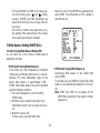
-19-
Left Button
Set Switch
Right Button
Down Button
Up Button
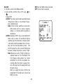
Up Button (): Moves the cursor upwards. Use
this button to select an item or
adjust the parameters.
Down Button (): Moves the cursor downwards. Use
this button to select an item or
adjust the parameters.
Right Button (): Moves the cursor to the right. Use
this button to select or adjust the
parameters of the selected item.
The parameter changes each time
this button is pressed.
2. SETUP OPERATION
This camera utilizes a user setup menu (CAM SET UP)
that is displayed on the monitor.
To set items on the CAM SET UP menu, use the follow-
ing buttons on the side panel.
Left Button (): Moves the cursor to the left. Use
this button to select or adjust the
parameters of the selected item.
The parameter changes each time
this button is pressed.
Set Button (): Executes selection and displays a
submenu for an item with mark.
END: Close Setup menu.
RET: Return to the previous menu
or page.
To return to the CAM SET UP menu move the cur-
sor to RET and press .
• All Reset Operation
All Reset allows you to reset all setup menu items to the
factory settings if you are unsure about the correct set-
tings. Proceed as follows:
(1) Make sure that the CAM SET UP menu is not dis-
played (a camera picture is displayed).
(2) While pressing both and , press for a
few seconds. The message ALL RESET momentari-
ly appears on the monitor.
This resets all adjustments and parameters to the
factory default settings.

-20-
• Editing the CAM SET UP Menu
Important Notice:
When SET UP DISABLE appears in the bottom line
of the CAM SET UP menu, you cannot change the
currently active settings. This is to prevent acciden-
tal changing of the settings.
To edit the CAM SET UP menu (change settings), press
and or and to move the cursor to SET
UP DISABLE in the bottom line.
Press . SET UP DISABLE changes to SET UP
ENABLE. Move the cursor to END, then to the item(s)
you want to change.
Important Notice:
When the cursor is moved to END and the CAM
SET UP menu closed after changing the parame-
ters, the new values are saved in the EEPROM
(Electric Erasable and Programmable Read Only
Memory). These values remain valid until new val-
ues are saved, even if the power of the camera is
off.
** CAM SET UP **
CAMERA ID OFF
ALC/ELC ALC
SHUTTER OFF
AGC ON (DNR-H)
SENS UP OFF
SYNC INT
WHITE BAL ATW1
MOTION DET OFF
LENS DRIVE DC
END SET UP DISABLE
↵↵
↵
** CAM SET UP **
CAMERA ID OFF
ALC/ELC ALC
SHUTTER OFF
AGC ON (DNR-H)
SENS UP OFF
SYNC INT
WHITE BAL ATW1
MOTION DET OFF
LENS DRIVE DC
END SET UP ENABLE
↵↵
↵

-21-
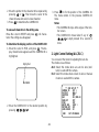
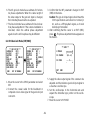
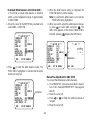
1. Camera Identification (CAMERA ID)
Setting
You can use the camera identification (CAMERA ID) to
assign a name to the camera. The camera ID consists
of up to 16 alphanumeric characters. The camera ID
display can be switched on or off on the monitor
screen.
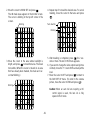
To edit the CAMERA ID
1. Move the cursor to the CAMERA ID parameter.
2. Press . The CAMERA ID menu appears. The
cursor on the letter “0” is highlighted.
3. Move the cursor to the character you want to edit
by pressing ///.
4. After selecting the character, press . The
selected character appears in the editing area.
(The pointer in the editing area moves to the right
automatically at this moment.)
5. Repeat the steps above until all characters are edit-
ed.
To enter a blank space in the CAMERA ID
Move the cursor to SPACE and press .
To replace a specific character in the CAMERA ID
1. Move the cursor to the editing area by pressing
.
** CAM SET UP **
CAMERA ID OFF
ALC/ELC ALC
SHUTTER OFF
AGC ON (DNR-H)
SENS UP OFF
SYNC INT
WHITE BAL ATW1
MOTION DET OFF
LENS DRIVE DC
END SET UP ENABLE
↵↵
↵
SETTING PROCEDURES
Character Cursor
Pointer
Character
Area
Command
Editing
Area
CAMERA ID menu
0123456789
ABCDEFGHIJKLM
NOPQRSTUVWXYZ
().,'":;&#!?=
+-*/%$ÄÜÖÆÑÅ
SPACE
POSI RET END RESET
................

-22-
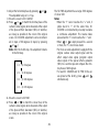
2. Move the pointer to the character to be replaced by
pressing or . Then move the cursor to the
character area and select a new character.
3. Press to determine the CAMERA ID.
To erase all characters in the editing area
Move the cursor to RESET and press . All charac-
ters in the editing area disappear.
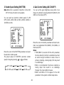
To determine the display position of the CAMERA ID
1. Move the cursor to POSI, and press . The dis-
play shown below appears and the CAMERA ID is
highlighted.
Highlighted
2. Move the CAMERA ID to the desired position by
pressing ///.
3. Press to fix the position of the CAMERA ID.
The mode returns to the previous CAMERA ID
menu.
Notes:
• The CAMERA ID stops at the edges of the mon-
itor screen.
• The CAMERA ID moves faster if any of /
/ / is kept pressed for a second or
more.
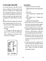
2. Light Control Setting (ALC/ELC)
You can select the mode for adjusting the lens iris.
The modes are as follows:
ALC: Select this mode when an auto iris lens (ALC
lens) is used with this camera.
ELC: Select this mode when a fixed iris lens or manual
iris lens is used with this camera.
WV-CL920
** CAM SET UP **
CAMERA ID OFF
ALC/ELC ALC
SHUTTER OFF
AGC ON (DNR-H)
SENS UP OFF
SYNC INT
WHITE BAL ATW1
MOTION DET OFF
LENS DRIVE DC
END SET UP ENABLE
↵↵
↵
Page is loading ...
Page is loading ...
Page is loading ...
Page is loading ...
Page is loading ...
Page is loading ...
Page is loading ...
Page is loading ...
Page is loading ...
Page is loading ...
Page is loading ...
Page is loading ...
Page is loading ...
Page is loading ...
Page is loading ...
Page is loading ...
Page is loading ...
Page is loading ...
Page is loading ...
Page is loading ...
Page is loading ...
Page is loading ...
-
 1
1
-
 2
2
-
 3
3
-
 4
4
-
 5
5
-
 6
6
-
 7
7
-
 8
8
-
 9
9
-
 10
10
-
 11
11
-
 12
12
-
 13
13
-
 14
14
-
 15
15
-
 16
16
-
 17
17
-
 18
18
-
 19
19
-
 20
20
-
 21
21
-
 22
22
-
 23
23
-
 24
24
-
 25
25
-
 26
26
-
 27
27
-
 28
28
-
 29
29
-
 30
30
-
 31
31
-
 32
32
-
 33
33
-
 34
34
-
 35
35
-
 36
36
-
 37
37
-
 38
38
-
 39
39
-
 40
40
-
 41
41
-
 42
42


Panasonic WVCL920_SERIES Operating instructions
- Category
- Security cameras
- Type
- Operating instructions
Ask a question and I''ll find the answer in the document
Finding information in a document is now easier with AI
Related papers
-
Panasonic WV-CP474H User manual
-
-
-
-
-
Panasonic WVCW474 Operating instructions
-
-
-
-
Other documents
-
 CAMECHO CM00-L0210 Installation guide
-
Sanyo VCC-5972P User manual
-
Samsung Digital Camera 510N User manual
-
 American Dynamics Tyco ADC770 Instructions Manual
-
-
JVC TK-S250 User manual
-
Philips LDH 0462/00 User manual
-
Optimus CC-CC14 User manual
-
 Teli CS5131P Operating instructions
-


