Cabletron Systems 9000 Reference guide
- Category
- Networking
- Type
- Reference guide

9032052-02
SmartSwitch 9000
9T125-08
Local Management Appendix


1
Appendix
9T125-08 Module Specific
Information
Introduction
This appendix contains local management information that is specific to the
9T125-08 Token Ring MicroLAN Switch Module.
Module Interfaces
The 9T125-08 Token Ring MicroLAN Switch Module has five interfaces. Table 1
lists the identifying number, name, and description of each interface.
Table 1. 9T125-08 Module Interfaces
System
Interface
Number
Bridge
Interface
Number
Interface
Name
Interface
Description
1 SMB-1 1 Mbps System Management Bus
2 SMB-10 10 Mbps System Management Bus
3 1 FNB Flexible Network Bus (FDDI)
4 2 TOKEN RING 1 Token Ring 1 Front Panel Interface
5 3 TOKEN RING 2 Token Ring 2 Front Panel Interface

9T125-08 Module Specific Information
2
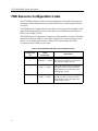
FNB Resource Configuration Codes
The 9T125-08 Module provides connectivity between one of three interfaces: the
front panel Token Ring interface(s) and the FDDI rings on the backplane (FNB-1
or FNB-2).
The FNB Resource Configuration Screen allows you to connect the module’s front
panel Token Ring interface to one of the chassis’ two FDDI networks (FNB-1 or
FNB-2) via a bridge/switch.
The FNB Resource Configuration Screen lists all the possible connections that the
specified module can support on the FNB, displays the current connection, and
allows you to change the connection. Table 2 lists and describes the FDDI
Connections from which you can select.
Table 2. 9T125-08 Module FNB Resource Configuration Codes
Configuration
ID
FDDI
Connections
Description
1 NORING <-> TRNG
Neither the FNB-1 nor the FNB-2 on
the chassis’ backplane is connected to
the module’s bridge/switch.
2 FNB1 <-> TRNG
The FNB-1 on the chassis’ backplane
and the module’s front panel Token
Ring interfaces are connected to the
same bridge/switch.
3 FNB2 <-> TRNG
The FNB-2 on the chassis’ backplane
and the module’s front panel Token
Ring interfaces are connected to the
same bridge/switch.

3
9T125-08 Module Specific Information
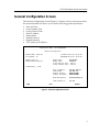
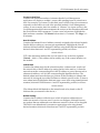
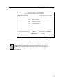
General Configuration Screen
The General Configuration Screen (Figure 1), displays various information about
the selected module and allows you to set the following general parameters:
• Date and Time
• Screen Update Time
• Screen Lockout Time
• Host IP Address
• Subnet Mask
• Default Gateway
• Default Interface
• TFTP Gateway IP Address
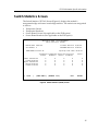
Figure 1. General Configuration Screen
SmartSwitch 9000 Local Management
General Configuration
Module Name: 9T125-08 Firmware Revision: 01_00_00
Slot Number: 10 BOOTPROM Revision: 01.00.05
Module Serial #: Module Date: 04/15/1997
Module Board Revision: Module Time: 14:02:11
Screen Refresh Time: 03 sec
Screen Lockout Time: 15 min
FLASH Memory: 0 MB
Host IP Address: 134.141.144.117
Subnet Mask: 255.255.0.0
Default Gateway: NONE DEFINED
Default Interface: NONE DEFINED
Base MAC Address: 00-00-1D-2E-02-5C
TFTP Gateway IP: 0.0.0.0
SAVE EXIT RETURN

9T125-08 Module Specific Information
4
General Configuration Screen Fields
The following information briefly explains each General Configuration Screen
field.
Module Serial #
Displays the serial number of the selected module.
Module Board Revision
Displays the version number of the selected module.
FLASH Memory
Displays the amount (megabytes) of flash memory in the selected module.
Module Date
Contains a value that the module recognizes as the current date. To enter a new
date, highlight the field and enter the date in MM/DD/YYYY format. The month
and day portion of the date must include two digits. Therefore, enter a leading
zero for months January through September, and for dates less than 10. For
example, for June 4, 1996, enter 06/04/1996 (slashes are optional). If you do not
enter slashes to separate the month, day, and year values, the first eight digits you
enter in this field represent an entry (i.e., 06041996).
Module Time
Contains a value that the module recognizes as the current time. To enter a new
time, highlight the field and enter the time in HH:MM:SS format. Notice that
there is no AM/PM indicator. Time should be entered based upon a 24 hour clock.
For 4:07 p.m., enter 16:07:00 (colons are optional). If you do not enter colons to
separate the hours, minutes, and seconds values, the first six digits you enter in
this field represent an entry (i.e., 160700). For 6:12 a.m., enter 6:12:00 or 061200.
Screen Refresh Time
Contains the rate at which the module’s screens are updated. This setting
determines how frequently (in seconds) information is updated on the screen. To
enter a new refresh rate, highlight the field and enter a number. The
default
refresh rate is 3 seconds. The
range
is 3 - 99 seconds.
The module’s default date and time settings are indeterminate. The internal
calendar and clock begin running as soon as you install the module.
NOTE

5
9T125-08 Module Specific Information
Screen Lockout Time
Contains the maximum number of minutes that the Local Management
application will display a module’s screen while pending input or action from a
user. For example, if you enter 5 in this field, users will have up to five minutes to
respond in some fashion to each of the specified module’s Local Management
screens. In our example, after five minutes of “idleness” (no input or action), the
Local Management application terminates the session on the selected module and
the Slot Selection Screen reappears. To enter a new lockout time, highlight the
field and enter a number. The
default
lockout time is 15 minutes. The
range
is 1 -
30 minutes.
Host IP Address
Contains the Internet Protocol address currently assigned to the selected module.
Set this field according to your network requirements. Highlight the Host IP
Address field and enter the desired IP address using dotted decimal notation (4
decimal values between 1 and 255 separated by periods) as follows:
255.255.255.255
(255 is the maximum number that you can enter in any of the four segments.
Default
= 0.0.0.0 .) This address can be used by any of the system interfaces on
the module.
Subnet Mask
Contains the subnet mask for the selected module. A subnet mask “masks out”
the network bits of the IP address by setting the bits in the mask to 1 when the
network treats the corresponding bits in the IP address as part of the network or
subnetwork address, or to 0 if the corresponding bit identifies the host. The
default subnet mask uses the first two portions of the IP address to identify the
network id, leaving the rest of the IP address to identify specific nodes. To enter a
new subnet mask, highlight the field and enter a new value using dotted decimal
notation (4 decimal values between 1 and 255 separated by periods) as follows:
255.255.255.255
(The Subnet Mask field defaults to the natural mask value, based on the IP
Address that you entered for the device.)
Default Gateway
Contains the IP Address of the device to which all packets addressed to an
unknown network or host are sent. If you do not configure a Default Gateway,
any packets that are addressed to an unknown network or host will be dropped.
This field is not defined until you enter an appropriate value using dotted
decimal notation (4 decimal values between 1 and 255 separated by periods).

9T125-08 Module Specific Information
6
Default Interface (Toggle)
Contains the number that represents the interface that is connected to the
module’s Default Gateway. In some instances, dissimilar modules have different
corresponding interface numbers. For example, if you are assigning a default
interface to a 9E133-36 module and you enter a 3, then the default interface is the
Flexible Network Bus. However, if you are assigning a default interface to a
9F310-02 module and you enter a 3, then the default interface is the Internal
Network Bus. See Table 1 for module-specific interface information. The
default
is NONE, meaning no default interface selected.
Base MAC Address
Displays the MAC Address of the selected module. This is the MAC Address of
the SMB-10 interface.
TFTP Gateway IP
The IP address of the router that connects to or is closest to the module. Configure
this address when you are performing TFTP downloads in a routed environment
(if proxy ARP is disabled on the router).
The Default Interface field becomes active after you enter an IP address in the
Default Gateway field.
NOTE

7
9T125-08 Module Specific Information
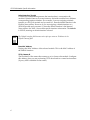
Switch Configuration Screen
The Switch Configuration Screen (Figure 2), provides basic setup options for
making a switch operational in your network.
Figure 2. Switch Configuration Screen
SmartSwitch 9000 Local Management
Switch Configuration
Module Name: 9T125-08 Firmware Revision: 01_00_00
Slot Number: 10 BOOTPROM Revision: 01.00.05
Bridge Address: 00-00-1D-2E-02-5C Bridging Interfaces: 3
Bridge Priority Label (hex): 8000 Type of STA: [IEEE]
Bridge Path Cost (hex): 0000000A Novell Xlat: [NONE]
Interface MAC/Local Address Ring Bridge Status
Speed State
1 (FNB) 00-00-B8-74-40-BA 100 forwarding [ENABLED]
2 (TR1) 00-00-B8-74-40-7A [16] forwarding [ENABLED]
3 (TR2) 00-00-B8-74-40-FA [16] forwarding [ENABLED]
SAVE SRT CONFIGURATION EXIT RETURN
To modify a non-toggle field on this screen, use the arrow keys to highlight the
field, then press the Enter key. Now you can modify the field.
NOTE

9T125-08 Module Specific Information
8
Switch Configuration Screen Fields
The following information briefly explains each Switch Configuration Screen
field.
Bridge Address
Displays the MAC Address of the bridge.
Bridge Priority Label
Allows you to enter a hexadecimal number that identifies the write-able portion
of the Bridge ID, i.e., the first two octets of the Bridge ID. Valid bridge priority
labels
range
from 0000 to FFFF.
Bridge Path Cost
Allows you to enter (as a hexadecimal number) the cost of the path to the root as
seen from the specified bridge. Valid bridge path costs
range
from 00000001 to
0FFFFFFF.
Bridging Interfaces
Displays the total number of bridging interfaces on the selected module.
Type of STA (Toggle)
Allows you to set the method that bridges use to decide which bridge is the
controlling (Root) bridge when two or more bridges exist in parallel (Spanning
Tree Algorithm). Valid entries include IEEE and NONE. Press the Space Bar to
toggle to the desired value.
Novell Xlat (Toggle)
Specifies the type of address swapping for Novell translation. Novell Xlat is one
of the following:
• NONE - Address swapping is disabled
• DLC - Bit reversal of the datalink destination address and source address
• LLC - Bit reversal of Netware payload-based MAC addresses
Press the Space Bar to toggle to the desired value. You must SAVE your choice for
it to affect Novell translation.
Interface
Lists each bridge interface on the selected module: FNB, TR1, and TR2.
All bridges in a network must use the same Spanning Tree protocol. The IEEE
protocol has a unique format for its Bridge Protocol Data Units (BPDU). Trying
to mix STA protocols results in an unstable network.
!
CAUTION

9
9T125-08 Module Specific Information
MAC/Local Address
Lists the hardware address of each listed bridge interface.
Ring Speed (Toggle)
Allows you to set each token ring interface’s operating speed (either 4 Mbps or 16
Mbps). Press the Space Bar to toggle to the desired value.
Bridge State
Displays the current state of each listed interface. The possible interface states
include:
Disabling: Management has disabled this interface. No traffic can be received
or forwarded while the interface is disabled.
Learning: The bridge is learning this interface’s network addresses. The
bridge enters the learning state when the Transparent Database is
created (during start-up or after being deleted), or when the
Spanning Tree Algorithm detects a network topology change.
Listening: The bridge is not adding information to the Transparent Database.
The bridge is monitoring BPDU traffic while preparing to move
from the learning to the forwarding state.
Forwarding: The bridge is on-line and this interface is forwarding traffic.
Blocking: This interface will not forward any traffic through the bridge.
Status (Toggle)
Allows you to set the bridge forwarding status of the listed interface (either
ENABLED or DISABLED). Press the Space Bar to toggle to the desired value.
Displaying the SRT Configuration Screen
To display the SRT Configuration Screen, use the arrow keys to highlight SRT
CONFIGURATION, then press the Return key.

9T125-08 Module Specific Information
10
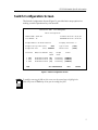
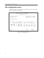
SRT Configuration Screen
The SRT Configuration Screen (Figure 3), provides basic setup options for making
a switch operational in your network.
Figure 3. SRT Configuration Screen
SmartSwitch 9000 Local Management
SRT Configuration
Module Name: 9T125-08 Firmware Revision: 01_00_00
Slot Number: 10 BOOTPROM Revision: 01.00.05
Bridge Number (hex): 1
Interface Ring Hop Bridge Explorer |--SRT Protocol Transmission-----|
Number Count Method Type TCP/IP IPX SNA NetBios Other
1 (FNB) 001 TP TP
2 (TR1) 002 6 [SRT] [STE] [ SR ] [ SR ] [ SR ] [ SR ] [ SR ]
3 (TR2) 003 6 [SRT] [STE] [ SR ] [ SR ] [ SR ] [ SR ] [ SR ]
SAVE EXIT RETURN

11
9T125-08 Module Specific Information
SRT Configuration Screen Fields
The following information briefly explains each SRT Configuration Screen field.
Bridge Number
Allows you to enter a hexadecimal number that uniquely identifies a bridge when
more than one bridge is used to span the same two segments. Valid bridge
numbers range from 01 to 0F (15).
Interface
Lists each bridge interface on the selected module: FNB, TR1, and TR2.
Ring Number
Allows you to set the hexadecimal number that uniquely identifies the ring to
which the specified interface is connected. Valid ring numbers range from 001 to
FFF.
Hop Count
Allows you to set the maximum number (1 through 6) of routing descriptors
allowed in All Routes or Spanning Tree Explorer frames.
Bridge Method (Toggle)
Displays one of the following bridge methods:
• Source Route (SR) - All frames from the FNB are forwarded on the front panel
Token Rings with a source route RIF. There is no transparent frame support.
The Token Ring interface may only receive and transmit SR frames in this
mode. All TP frames are filtered when they are received by the Token Ring
interface.
• Source Route Transparent (SRT) - Performs source route bridging when
required, transparent bridging when required, and translational bridging. The
Token Ring interface can receive and transmit both SR and TP frames.
• Transparent (TP) - There is no source routing support. The bridge performs
transparent 802.1d bridging. All SR frames are filtered when they are received.

9T125-08 Module Specific Information
12
SRT Protocol Transmission (Toggle)
When the destination address is unknown, SRT Protocol Transmission specifies
the method of transmission, per protocol, onto the Token Ring. Valid methods are:
• SR - Source Route packet
• TP - Transparent packet
• Auto - Transmits both an SR and a TP packet
Table 3. Bridge Methods and Explorer Type Choices
Bridge Method Explorer Type Choices
TP
TP - Frames that are destined for an unknown destination
address (not in bridge database) or a broadcast destination
address are forwarded on to the Token Ring(s) as TP frames.
No translation for source routing is performed.
SR
ARE - Frames that are destined for an unknown destination
address (not in bridge database) or a broadcast destination
address are forwarded onto the Token Ring(s) as All Route
Explorer (ARE) frames. FDDI TP frames are translated to
this type of source routed frame.
STE - Frames that are destined for an unknown destination
address (not in bridge database) or a broadcast destination
address are forwarded onto the Token Ring(s) as Spanning
Tree Explorer (STE) frames. FDDI TP frames are translated
to this type of source routed frame.
SRT (default)
ARE (See ARE definition above)
STE (See STE definition above). This is the default.
These methods only appear when the Bridge Method is set to SRT.
NOTE

13
9T125-08 Module Specific Information
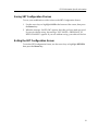
Saving SRT Configuration Choices
To save your modifications of the values on the SRT Configuration Screen:
1. Use the arrow keys to highlight SAVE at the bottom of the screen, then press
the Return key.
2. When the message “SAVED OK” appears, the edits you have made are saved.
If you exit without saving, the message “NOT SAVED -- PRESS SAVE TO
KEEP CHANGES” appears. If you exit without saving, your edits will be lost.
Exiting the SRT Configuration Screen
To exit the SRT Configuration Screen, use the arrow keys to highlight RETURN,
then press the Return key.

9T125-08 Module Specific Information
14
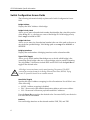
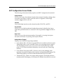
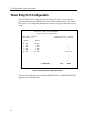
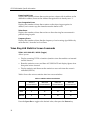
Token Ring Port Configuration
The Token Ring Port Configuration Screen (Figure 4), allows you to view the
current operational and administrative status of the module’s ports. This screen
also allows you to change the administrative status of each port (turn each port on
or off).
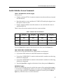
Figure 4. Token Ring Port Configuration Screen
The current configuration mode (either OPERATIONAL or ADMINISTRATIVE)
appears on the command line.
SmartSwitch 9000 Local Management
Token Ring Port Configuration
Module Name: 9T125-08 Firmware Revision: 01_00_00
Slot Number: 10 BOOTPROM Revision: 01.00.05
RING #1 RING #2
RO WRP RO WRP ^
1 ENB 1 ENB |
2 ENB 2 ENB |
3 ENB 3 ENB |
4 ENB 4 ENB
RI WRP RI WRP Token Flow
|
|
|
|
|
[ OPERATIONAL ] EXIT RETURN

15
9T125-08 Module Specific Information
Token Ring Port Configuration Screen Fields
The following information briefly explains each Token Ring Port Configuration
Screen field.
Ring #
Displays the current status/settings of the module ports that are attached to each
token ring. The information that appears, and whether that information is
modifiable, varies according to the configuration mode you select.
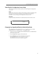
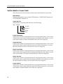
Token Flow
Graphically displays the direction in which the token travels. In other words:
Changing From Operational Mode to Administrative Mode
The configuration mode command allows you to toggle between two values:
ADMINISTRATIVE or OPERATIONAL. To change the mode:
1. Use the arrow keys to highlight either ADMINISTRATIVE or OPERATIONAL
at the bottom of the screen.
2. Press the Space Bar to toggle to the desired mode.
3. Press the Return key. The selected mode becomes effective.
The ADMINISTRATIVE mode is detailed on page 16.
The OPERATIONAL mode is detailed on page 18.
RI 4 3 2 1 Bridge RO
Interface

9T125-08 Module Specific Information
16
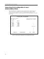
Token Ring Port Configuration Screen -
Administrative Mode
The Token Ring Port Configuration Screen (Administrative Mode) (Figure 5),
allows you to turn a module’s ports ON (administratively enable) or OFF
(administratively disable). You can turn ports ON/OFF individually or all on the
token ring.
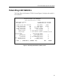
Figure 5. Token Ring Port Configuration Screen (Administrative Mode)
SmartSwitch 9000 Local Management
Token Ring Port Configuration
Module Name: 9T125-08 Firmware Revision: 01_00_00
Slot Number: 10 BOOTPROM Revision: 01.00.05
RING #1 RING #2
RO [ON ] RO [ON ] ^
1 [ON ] 1 [ON ] |
2 [ON ] 2 [ON ] |
3 [ON ] 3 [ON ] |
4 [ON ] 4 [ON ]
RI [ON ] RI [ON ] Token Flow
|
|
|
|
|
[ ENABLE ALL ] [ADMINISTRATIVE] EXIT RETURN

17
9T125-08 Module Specific Information
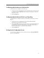
Configuring Administratively an Individual Port
To administratively configure an individual port:
1. Use the arrow keys to highlight the value in the field of the port that you want
to configure. Press the Space Bar until the desired value appears in the field
(either ON or OFF).
2. Press the Return key.
Configuring Administratively All Ports on a Token Ring
To administratively configure all ports on a Token Ring (Token Ring 1 or Token
Ring 2):
1. Use the arrow keys to highlight the value in the ENABLE/DISABLE
command (lower left portion of the screen).
2. Press the Space Bar until the desired value appears in the field (ENABLE ALL
or DISABLE ALL, ENABLE TOKEN RING 1 or DISABLE TOKEN RING 1,
ENABLE TOKEN RING 2 or DISABLE TOKEN RING 2).
3. Press the Return key.
Exiting the Port Configuration Screen
To exit the Port Configuration Screen, use the arrow keys to highlight RETURN,
then press the Return key.

9T125-08 Module Specific Information
18
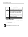
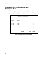
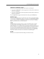
Token Ring Port Configuration Screen -
Operational Mode
The Port Configuration Screen (Operational Mode) (Figure 6), displays the
current status of each port in the module’s token ring. The status value that
appears in a port’s field is determined by the type of port (Lobe or RI/RO), and its
administrative status (On/Off).
Figure 6. Port Configuration Screen (Operational Mode)
SmartSwitch 9000 Local Management
Token Ring Port Configuration
Module Name: 9T125-08 Firmware Revision: 01_00_00
Slot Number: 10 BOOTPROM Revision: 01.00.05
RING #1 RING #2
RO WRP RO WRP ^
1 ENB 1 ENB |
2 ENB 2 ENB |
3 ENB 3 ENB |
4 ENB 4 ENB
RI WRP RI WRP Token Flow
|
|
|
|
|
[ OPERATIONAL ] EXIT RETURN
Page is loading ...
Page is loading ...
Page is loading ...
Page is loading ...
Page is loading ...
Page is loading ...
Page is loading ...
Page is loading ...
Page is loading ...
Page is loading ...
Page is loading ...
Page is loading ...
Page is loading ...
Page is loading ...
Page is loading ...
Page is loading ...
-
 1
1
-
 2
2
-
 3
3
-
 4
4
-
 5
5
-
 6
6
-
 7
7
-
 8
8
-
 9
9
-
 10
10
-
 11
11
-
 12
12
-
 13
13
-
 14
14
-
 15
15
-
 16
16
-
 17
17
-
 18
18
-
 19
19
-
 20
20
-
 21
21
-
 22
22
-
 23
23
-
 24
24
-
 25
25
-
 26
26
-
 27
27
-
 28
28
-
 29
29
-
 30
30
-
 31
31
-
 32
32
-
 33
33
-
 34
34
-
 35
35
-
 36
36


Cabletron Systems 9000 Reference guide
- Category
- Networking
- Type
- Reference guide
Ask a question and I''ll find the answer in the document
Finding information in a document is now easier with AI
Related papers
-
 Cabletron Systems MMAC-Plus 9F116-01 Reference guide
-
 Cabletron Systems SmartSwitch 9000 9T122-08 User manual
-
 Cabletron Systems MMAC-Plus 9T122-24 Reference guide
-
 Cabletron Systems 9G421-02 User manual
-
 Cabletron Systems 9F120-08 User manual
-
 Cabletron Systems 9F120-08 User manual
-
 Cabletron Systems TRMM User manual
-
 Cabletron Systems 9F241-12 Appendix
-
 Cabletron Systems TRBMIM User manual
-
 Cabletron Systems MMAC-Plus 9F310-02 Appendix


Other documents
-
3com SUPERSTACK II 2000 TR User manual
-
IBM Nways 8260 User manual
-
-
Enterasys Networks Element Manager 2.2.1 User manual
-
 Olicom CrossFire 8600 User manual
-
 Baicells Nova-233 G2 Installation Installation
-
iO HVAC Controls iO-WRP-B User manual
-
Iadea PRB-101 User guide
-
 Airspan Networks PIDAU540ENB25 User manual


