Ihse Draco CPU Switch (Series 484) User manual
- Type
- User manual

IHSE GmbH Benzstraße 1 88094 Oberteuringen Germany
Draco
484 Series
CPU Switch
User Manual
Edition: 2020-07-09

Draco CPU Switch
2 2020-07-09
Copyright
© 2021. All rights reserved. This information may not be reproduced in any
manner without the prior written consent of the manufacturer.
Information in this document is subject to change without notice.
Trademarks
All trademark and trade names mentioned in this document are
acknowledged to be the property of their respective owners.

Contents
2020-07-09 3
Contents
1 About This Manual ....................................................................... 6
1.1 Scope .................................................................................. 6
1.2 Validity ................................................................................ 6
1.3 Cautions and Notes ............................................................ 6
1.4 EU Declaration of Conformity .............................................. 6
2 Safety Instructions ....................................................................... 7
3 Description ................................................................................... 8
3.1 Application .......................................................................... 8
3.2 System Overview ................................................................ 9
3.3 Product Range .................................................................. 10
3.4 Upgrade Kits ..................................................................... 10
3.5 Accessories ....................................................................... 10
3.6 Device Views .................................................................... 11
3.6.1 Model L484-8VHCWR, -8VECWR ...................... 11
3.6.2 Model L484-8VHSWR, -8VESWR ...................... 12
3.7 Status LEDs ...................................................................... 13
4 Installation .................................................................................. 15
4.1 Package Contents ............................................................. 15
4.2 System Setup .................................................................... 15
4.3 Example Applications ........................................................ 16
5 Configuration .............................................................................. 17
5.1 Command Mode ............................................................... 17
5.2 Control via Keyboard......................................................... 18
5.3 On Screen Display (OSD) ................................................. 20
5.3.1 Main Menu Item 'Color Settings' ......................... 21
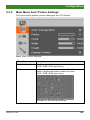
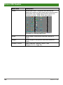
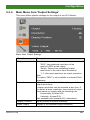
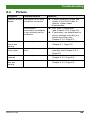
5.3.2 Main Menu Item 'Picture Settings' ....................... 23
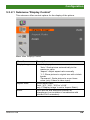
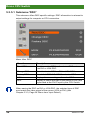
5.3.3 Main Menu Item 'Input Settings' .......................... 26
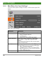
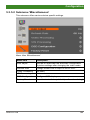
5.3.4 Main Menu Item 'Output Settings' ....................... 27
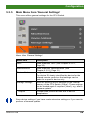
5.3.5 Main Menu Item 'General Settings' ..................... 29

Draco CPU Switch
4 2020-07-09
6 Operation .................................................................................... 33
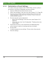
6.1 Optimization of Picture Settings ........................................ 33
6.1.1 Optimization of Output Settings .......................... 33
6.1.2 Optimization of Input Settings ............................. 34
6.1.3 Optimization of Picture Settings .......................... 35
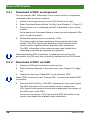
6.2 Download of DDC Information .......................................... 35
6.2.1 Download of DDC via Keyboard ......................... 36
6.2.2 Download of DDC via OSD ................................. 36
6.2.3 Further DDC settings .......................................... 37
6.3 Shared Operation .............................................................. 37
7 Specifications ............................................................................. 39
7.1 Interfaces .......................................................................... 39
7.1.1 VGA .................................................................... 39
7.1.2 USB-HID ............................................................. 39
7.1.3 USB 2.0 (transparent) ......................................... 39
7.1.4 Analog Audio Interface ........................................ 40
7.1.5 RJ45 (Interconnect) ............................................ 40
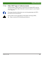
7.1.6 Fiber SFP Type LC (Interconnect) ...................... 41
7.2 Interconnect Cable ............................................................ 42
7.2.1 Cat X ................................................................... 42
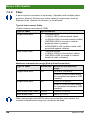
7.2.2 Fiber .................................................................... 44
7.3 Connector Pinouts ............................................................ 45
7.4 Power Supply .................................................................... 47
7.5 Environmental Conditions ................................................. 47
7.6 Size ................................................................................... 47
7.7 Shipping weight ................................................................. 47
8 Troubleshooting ......................................................................... 48
8.1 Blank Screen ..................................................................... 48
8.2 Picture ............................................................................... 49
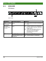
8.3 USB-HID ........................................................................... 50
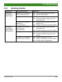
8.4 Analog Audio ..................................................................... 51

Contents
2020-07-09 5
9 Technical Support ...................................................................... 52
9.1 Support Checklist .............................................................. 52
9.2 Shipping Checklist ............................................................ 52
10 Directives .................................................................................... 53
10.1 North American Regulatory Compliance ........................... 53
10.2 WEEE ............................................................................... 53
10.3 RoHS/RoHS 2 ................................................................... 53
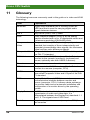
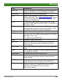
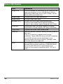
11 Glossary ...................................................................................... 54
Pos: 1 /806-IHSE/Zu di esem Handbuch/ATB_Zu di esem Handbuch @ 5\mod_12785731632 76_6.doc @ 41510 @ 1222 @ 1

Draco CPU Switch
6 2020-07-09
1 About This Manual
1.1 Scope
This manual describes how to install your CPU Switch, how to operate it
and how to perform trouble shooting.
1.2 Validity
This manual is valid for all devices listed on the front page. The product
code is printed on the base of the devices.
1.3 Cautions and Notes
The following symbols are used in this manual:
This symbol indicates an important operating instruction that should be
followed to avoid an
y potential damage to hardware or property, loss of
data, or pers
onal injury.
This symbol indicates important information to help you make the best use
of this product.
This symbol indicates best practice information to show recommended
and optima
l ways to use this product in an efficient way.
Pos: 2 /806-IHSE/Sic herheitshinweise/ ATB_Sicherheitshi nweise @ 5\mod_1278573321245_6. doc @ 41528 @ 1 @ 1
1.4 EU Declaration of Conformity
Please find the EU Declaration of Conformity for the product series under:
www.ihse.com/eu-declaration-of-conformity
A copy of the original, product-specific EU Declaration of Conformity can
be provided upon request.

Safety Instructions
2020-07-09 7
2 Safety Instructions
To ensure reliable and safe long-term operation of your CPU Switch
please note the following guidelines:
Installation
Only use in dry, indoor environments.
Only use the device according to this User Manual. Failure to follow
these procedures could result in damage to the equipment or injury to
the user or installer.
The CPU Switch and the power supply units can get warm. Do not
install components in an enclosed space without any airflow.
Do not place the power supply directly on top of the device.
Do not obscure ventilation holes.
Only use power supplies originally supplied with the product or
manufacturer-approved replacements. Do not use a power supply if it
appears to be defective or has a damaged chassis.
Connect all power supplies to grounded outlets. In each case, ensure
that the ground connection is maintained from the outlet socket
through to the power supply's AC power input.
Do not connect the link interface to any other equipment, particularly
network or telecommunications equipment.
Take any required ESD precautions.
In order to disconnect the device c
ompletely from the electric circuit, all
power cables have to be removed.
Repair
Do not attempt to open or repair a power supply unit.
Do not attempt to open or repair the CPU Switch. There are no user
serviceable parts inside.
Please contact your dealer or manufacturer if there is a fault.
Pos: 3 /806-IHSE/Besc hreibung/UEB_Bes chreibung @ 5\mod_127857337915 1_6.doc @ 41546 @ 1 @ 1

Draco CPU Switch
8 2020-07-09
3 Description
Pos: 4 /806-IHSE/Besc hreibung/Verwendung szweck/484-xx @ 12\mod_141018 0611529_6.doc @ 149293 @ 2 @ 1
3.1 Application
The CPU Switch is used to convert and extend video signals of one or
more VGA sources (computer, CPU) into the DVI-D format. The device
functions like a CPU Unit of a KVM extender.
The CPU Switch can be used as a switch between concurrently available
input signals.
Next to the video signal, USB-HID and analogue audio signals can be also
switched and extended.
The CPU Switch can further be used as a scaler, scaling video signals to
a specific output format.
Pos: 5 /806-IHSE/Besc hreibung/System-Ü bersicht /484-xx @ 12\mod_1410265888084_6. doc @ 149330 @ 2 @ 1

Description
2020-07-09 9
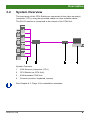
3.2 System Overview
The input ports of the CPU Switch are connected to the video source(s)
(computer, CPU), using the provided cables or other suitable cables.
The DVI-D monitor is connected to the output of the CON Unit.
System Overview
1 VGA Sources (computer, CPU)
2 CPU Switch (as CPU Unit)
3 KVM extender CON Unit
4 Console (monitor, keyboard, mouse)
See Chapter
4.3, Page 16 for installation examples.
Pos: 6 /806-IHSE/Besc hreibung/Gerät etypen/484-xx @ 1 2\mod_1410266166481_6. doc @ 149362 @ 2 @ 1

Draco CPU Switch
10 2020-07-09
3.3 Product Range
Model
Description
L484-
8VHCWR
8 port CPU Switch as a KVM extender CPU Unit with
integrated analog/digital conversion (up to 1920x1200)
and redundant connector for interconnect cables (Cat X),
USB-HID, local USB 2.0 (High-Speed), Analog Audio
L484-
8VHSWR
8 port CPU Switch as a KVM extender CPU Unit with
integrated analog/digital conversion (up to 1920x1200)
and redundant connector for interconnect cables (fiber),
USB-HID, local USB 2.0 (High-Speed), Analog Audio
L484-
8VECWR
8 port CPU Switch as a KVM extender CPU Unit with
integrated analog/digital conversion (up to 1920x1200)
and redundant connector for interconnect cables (Cat X),
USB-HID, USB 2.0 embedded, local USB 2.0 (High-
Speed), Analog Audio
L484-
8VESWR
8 port CPU Switch as a KVM extender CPU Unit with
integrated analog/digital conversion (up to 1920x1200)
and redundant connector for interconnect cables (fiber),
USB-HID, USB 2.0 embedded, local USB 2.0 (High-
Speed), Analog Audio
Pos: 7 /806-IHSE/Besc hreibung/Einbauopt ionen/484-xx @ 12\mod_1410266291185_6.doc @ 149394 @ 2 @ 1
3.4 Upgrade Kits
Model
Description
474-6RMK 19"/1U rack mount kit for CPU Switch
The CPU Switch and the pro
vided power supply units can get warm, for
this reason an installation in closed rooms without air circulation is not
allowed.
Please note that you will need at least 0,5 U (height unit) for the
ventilation above the extenders, if you mount them into racks
.
Pos: 8 /806-IHSE/Besc hreibung/Zubehör/ 484-xx @ 12\mod_1410266366097_6. doc @ 149426 @ 2 @ 1
3.5 Accessories
Model
Description
261-6J VGA cable 2.0 m (VGA male to VGA male)
247-U1 USB cable 1.8 m (Type A to B)
455-CK Stereo jack cable 1.6 m (3.5 mm Stereo)
474-IECLOCK IEC connection cable for power supply, lockable
Pos: 9 /806-IHSE/Besc hreibung/Gerät eansichten/UEB_Ger äteansichten @ 5\mod_12785737378 08_6.doc @ 41654 @ 2 @ 1

Description
2020-07-09 11
3.6 Device Views
Pos: 10 /806-IHSE/ Beschreibung/Gerät eansichten/484-xx/Typ L484-8VHCW R, -8VECWR @ 12\mod_1410266500817_6. doc @ 149464 @ 3 @ 1
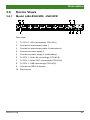
3.6.1 Model L484-8VHCWR, -8VECWR
Rear View
1 To CPU 1: VGA (accordingly CPU #2-8)
2
Connect to interconnect cable 1
3
Connect to interconnect cable 2 (redundancy)
4
Connect to power supply 1
5
Connect to power supply 2 (redundancy)
6
To CPU 1: Audio IN (accordingly CPU #2-8)
7
To CPU 1: Audio OUT (accordingly CPU #2-8)
8
To CPU 1: USB (accordingly CPU #2-8)
9
Connect to USB 2.0 devices
10
Service port
Pos: 11 /806-IHSE/ Beschreibung/Gerät eansichten/484-xx/Typ L484-8VHSWR, -8VESWR @ 12\mod_1410266657607_6.doc @ 149526 @ 3 @ 1

Draco CPU Switch
12 2020-07-09
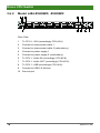
3.6.2 Model L484-8VHSWR, -8VESWR
Rear View
1 To CPU 1: VGA (accordingly CPU #2-8)
2
Connect to interconnect cable 1
3
Connect to interconnect cable 2 (redundancy)
4
Connect to power supply 1
5
Connect to power supply 2 (redundancy)
6
To CPU 1: Audio IN (accordingly CPU #2-8)
7
To CPU 1: Audio OUT (accordingly CPU #2-8)
8
To CPU 1: USB (accordingly CPU #2-8)
9
Connect to USB 2.0 devices
10
Service port
Pos: 12 /806-IHSE/ Beschreibung/Diagnos e LEDs/484-xx @ 12\mod_1410266739 486_6.doc @ 149552 @ 2 @ 1

Description
2020-07-09 13
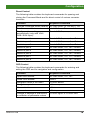
3.7 Status LEDs
The CPU Switch is fitted with a multi-color LED for indication of the
connection status:
Model L484
-8VHCWR, -8VECWR
Rear View
Model L484-8VHSWR, -8VESWR
Rear View
LED 1: Switching Status
Pos. LED Status Description
1 Input LED
(green)
Off Connection not available
On Video signal available
Flashing
rapidly
Channel selected, no video signal
available
Flashing
slowly
Channel selected, video signal available
LED 2 and 3: Connection Status
Pos. LED Status Description
2 Failure LED
(green)
Off Connection available
On or
Flashing
Connection failure (flashing for about
20 s following a connection failure)
3 Status LED
(green)
Flashing No connection via interconnect cable
On Connection available

Draco CPU Switch
14 2020-07-09
LED 5 and 7: USB and Video Status (Link 1/2)
Pos: 15 /806-IHSE/I nstallation/UEB_I nstallation @ 5\mod_127857497 1589_258.doc @ 41766 @ 1 @ 1
LED color
Description
Red
Device ready
Violet
Connection and USB signal (connection to extender)
available
Green
Connection and video signal available
Light
Blue
Connection, USB and video signal available
(operating condition)
LED 4 and 6: Power Supply Unit Status
Pos. LED Status Description
4 Status
PSU 2
(green)
On Operating condition
Off Power supply unit off
6 Status
PSU 1
(green)
On Operating condition
Off Power supply unit off
Pos: 13 /806-IHSE/Installation/UEB_Installat ion @ 5\mod_1278574971589_6.doc @ 41768 @ 1 @ 1

Installation
2020-07-09 15
4 Installation
Pos: 14 /806-IHSE/I nstallation/Lief erumfang prüfen/484-xx @ 12\mod_1410267027398_6.doc @ 149589 @ 2 @ 1
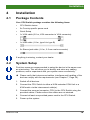
4.1 Package Contents
Your CPU Switch package contains the following items:
CPU Switch device
2x Country specific power cord
Quick Setup
1x VGA cable (2.0 m, VGA connector to VGA connector)
1x USB cable (1.8 m, type A to type B)
2x Stereo jack cable (1.6 m, 3.5 mm male connector)
If anything is missing, contact your d
ealer.
Pos: 15 /806-IHSE/Installation/System anschließen/484-x x @ 12\mod_1410267095048_6. doc @ 149620 @ 2 @ 1
4.2 System Setup
First time users are recommended to setup the device in the same room
as a test setup. This will allow you to identify and solve
any cabling
problems, and to ex
periment with your system more conveniently.
Please verify that interconnect cables, interfaces and handling of the
devices comply with the requirements (see Chapter 7, Page 39).
1. Switch off all devices.
2. Connect the CPU Switch to either a KVM extender CON Unit or a
KVM matrix via the interconnect cable(s).
3. Connect the sources (computer, CPU) to the CPU Switch using the
provided cables. Please ensure the cables are not strained.
4. Connect at least one provided power cord to the CPU Switch.
5. Power up the system.
Pos: 16 /806-IHSE/I nstallation/Inst allationsbeispi ele/484-xx @ 12\mod_1410267380099_6. doc @ 149651 @ 2 @ 1

Draco CPU Switch
16 2020-07-09
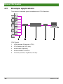
4.3 Example Applications
This section illustrates typical installations of CPU Switches:
Pos: 19 /806-IHSE/I nstallation/Inst allationsbeispi ele/238-5v-xx @ 5\mod_1291133686078_6. doc @ 45348 @ @ 1
CPU Switch
1 VGA sources (Computer, CPU)
2 CPU Switch (as CPU Unit)
3 KVM matrix (optional)
4 KVM extender CON Unit
5 Console (monitor, keyboard, mouse)
Pos: 17 /806-IHSE/ Konfiguration/UEB_Konf iguration @ 5\mod_1278575517073_6. doc @ 41846 @ 1 @ 1

Configuration
2020-07-09 17
5 Configuration
Pos: 18 /806-IHSE/Konf iguration/Kommando-Modus/ 476-xx @ 5\mod_1278947076886_6.doc @ 43540 @ 2 @ 1
5.1 Command Mode
The CPU Switch has a Command Mode that allows several functions via
keyboard command during normal use.
To enter Command Mode use a 'Hot Key' sequence and to exit Command
Mode, press <Esc>. While in Command Mode, the LEDs Shift and Scroll
on the console keyboard will flash.
In Comm
and Mode normal keyboard and mouse operation will cease.
Only selected keyboard commands a
re available.
If no keyboard command
is executed within 10 s after activating
Command Mode, it will be automatically deactivated.
The following table lists the keyboard commands to enter and to exit
Command Mode and to change the 'Hot Key' sequence:
Function Keyboard Command
Enter Command Mode
(default)
2x <Left Shift> (or 'Hot Key')
Exit Command Mode <Esc>
Change 'Hot Key' sequence <current 'Hot Key'>, <c>,
<new 'Hot Key' code>, <Enter>
Until 2011-30-09:
<Left Ctrl> + <Left Shift> + <c>,
<'Hot Key' Code>, <Enter>
<Key> + <Key>
Press keys simultaneously
<Key>, <Key>
Press keys successively
2x <Key>
Press key quickly, twice in a row
(similar to a mouse double-click)

Draco CPU Switch
18 2020-07-09
The 'Hot Key' sequence to enter Command Mode can be changed. The
following table lists the 'Hot Key' Codes for the available key sequences:
'Hot Key' Code 'Hot Key'
0 Freely selectable (2012-01-12)
2 2x <Scroll>
3 2x <Left Shift>
4 2x <Left Ctrl>
5 2x <Left Alt>
6 2x <Right Shift>
7 2x <Right Ctrl>
8 2x <Right Alt>
In a KV
M switch configuration, choose different 'Hot Keys' for the
KVM
Extender and the Draco CPU Switch.
Set freely selectable 'Hot Key' (exemplary)
In order to set a freely selectable 'Hot Key' (e.g. 2x <Space>), use the
following keyboard sequence:
<current 'Hot Key'>, <c>, <0>, <Space>, <Enter>
Reset 'Hot Key'
In order to set a 'Hot Key' back to default settings of the extender, press
the key combination <Right Shift> + <Del> within 5 s after switching on the
CON unit or plugging in a keyboard.
Pos: 19 /806-IHSE/ Konfiguration/Ans teuerung T astatur/484_Anst euerung über Tastat ur @ 12\mod_1410268630850_6.doc @ 149678 @ 2 @ 1
5.2 Control via Keyboard
The CPU Switch connected to a KVM extender KVM extender CON Unit
offers the possibility for control via keyboard.
For this purpose the CPU Switch is equipped with its own Command
Mode that can be used to activate various functions by keyboard
commands and to control the integrated On-screen Display (OSD).
The Command Mode is entered by a keyboard sequence ('Hot Key') and
can be closed using the key <Esc>. When Command Mode is activated,
the keyboard LEDs Shift and Scroll are flashing.

Configuration
2020-07-09 19
Direct Control
The following table contains the keyboard commands for opening and
closing the Command Mode and for direct control of various converter
functions.
Function Keyboard Command
Activate Command Mode (default) 2x <Left Shift> (or 'Hot Key'), <v>
Exit Command Mode <Left Shift> + <Esc>
Configure video settings
automatically (only with VGA /
RGB / EGA input)
2x <Left Shift>, <v>, <a>
Switch to port 1 2x <Left Shift>, <v>, <1>, <Enter>
Switch to port 2 2x <Left Shift>, <v>, <2>, <Enter>
Switch to port 3 2x <Left Shift>, <v>, <3>, <Enter>
Switch to port 4 2x <Left Shift>, <v>, <4>, <Enter>
Switch to port 5 2x <Left Shift>, <v>, <5>, <Enter>
Switch to port 6 2x <Left Shift>, <v>, <6>, <Enter>
Switch to port 7 2x <Left Shift>, <v>, <7>, <Enter>
Switch to port 8 2x <Left Shift>, <v>, <8>, <Enter>
OSD Control
The following table contains the keyboard commands for entering and
exiting the OSD and for navigation and configuration.
Function
Keyboard Command
Open OSD window 2x <Left Shift>, <v>, <o>
Close OSD window <Esc>
Navigation down in the menu <Cursor down>
Navigation up in the menu <Cursor up>
Menu selection <Enter>
Leave sub menu <Backspace>
Change of settings in sub menus
or selection of parameter values
<Cursor right> or <Cursor left>
Pos: 20 /806-IHSE/ Konfiguration/238_On-Scr een-Display (OSD)/ 238-5v-xx @ 5\mod_1291133855 468_6.doc @ 45368 @ 234343334 4 @ 1

Draco CPU Switch
20 2020-07-09
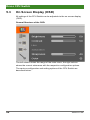
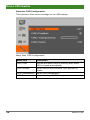
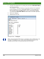
5.3 On Screen Display (OSD)
All settings of the CPU Switch can be adjusted via the on screen display
(OSD).
General Structure of the OSD:
The left column shows the range of the main menu, the right column
shows the current submenus with the respective configuration options.
The various configuration and setting options of the CPU Switch are
described below:
Page is loading ...
Page is loading ...
Page is loading ...
Page is loading ...
Page is loading ...
Page is loading ...
Page is loading ...
Page is loading ...
Page is loading ...
Page is loading ...
Page is loading ...
Page is loading ...
Page is loading ...
Page is loading ...
Page is loading ...
Page is loading ...
Page is loading ...
Page is loading ...
Page is loading ...
Page is loading ...
Page is loading ...
Page is loading ...
Page is loading ...
Page is loading ...
Page is loading ...
Page is loading ...
Page is loading ...
Page is loading ...
Page is loading ...
Page is loading ...
Page is loading ...
Page is loading ...
Page is loading ...
Page is loading ...
Page is loading ...
Page is loading ...
-
 1
1
-
 2
2
-
 3
3
-
 4
4
-
 5
5
-
 6
6
-
 7
7
-
 8
8
-
 9
9
-
 10
10
-
 11
11
-
 12
12
-
 13
13
-
 14
14
-
 15
15
-
 16
16
-
 17
17
-
 18
18
-
 19
19
-
 20
20
-
 21
21
-
 22
22
-
 23
23
-
 24
24
-
 25
25
-
 26
26
-
 27
27
-
 28
28
-
 29
29
-
 30
30
-
 31
31
-
 32
32
-
 33
33
-
 34
34
-
 35
35
-
 36
36
-
 37
37
-
 38
38
-
 39
39
-
 40
40
-
 41
41
-
 42
42
-
 43
43
-
 44
44
-
 45
45
-
 46
46
-
 47
47
-
 48
48
-
 49
49
-
 50
50
-
 51
51
-
 52
52
-
 53
53
-
 54
54
-
 55
55
-
 56
56


Ihse Draco CPU Switch (Series 484) User manual
- Type
- User manual
Ask a question and I''ll find the answer in the document
Finding information in a document is now easier with AI
Related papers
-
Ihse Draco K477 Series User manual
-
-
-
-
-
-
-
-
-
Other documents
-
 KVM-TEC Gateway 2G KVM Extender Over IP Installation guide
-
KVM-TEC kvm-tec KT-6013L-F Masterflex KVM Extender over IP Installation guide
-
master Easy kvm-tec Installation guide
-
 KVM-TEC KT -6930 Smarteasy SingleKT -6930 Full HD Single smarteasy User manual
-
 KVM-TEC ECOSMART Local Quick Instruction
-
KVM-TEC KT-6032L USBflex fiber Extender IP User manual
-
 KVM-TEC master EASY dual Fiber Quick Instruction
-
 KVM-TEC INDUSTRYFLEX SINGLE CAT Quick Instruction
-
KVM-TEC KT-6016iL CPU Single Fiber Redundant User manual
-
KVM-TEC kvm-tec KT-8121 SmartEasy Dual in Copper User manual


