Page is loading ...

UTILITY IRON BODY SERIES
DESCRIPTION
The rugged Powers Type SI (single seat iron body) balanced valve is primarily
used for steam and water modulating applications with moderate pressure
drops. The equal percent plug provides excellent control characteristics and is
more tolerant of oversizing than linear or quick-opening plugs. The SI’s
control and close off characteristics are particularly well-suited to commercial
water heaters, boilers, and industrial utility applications. The SI balanced valve
is available with the Powers 46 in.
2
and 100 in.
2
actuators. Actuator selection
depends on valve size and flowing system pressure drop across the valve.
SPECIFICATIONS
VALVE
Body Sizes: 2
1
⁄2" – 6"
Body Material: Cast Iron (per
ASTM A126-93 Class B)
End Connections: 125 # Flanged (per
ANSI B16.1–1993)
Trim: Bronze Composition Disc
Packing: Spring loaded TFE/EPDM packing
Seat Leakage: ANSI Class IV < 0.01% leakage
Close-off Pressure: 125psi
Cv Range: 56-370
Rangeability: 100:1
Characteristics: Equal Percent
Maximum Pressure: 200 psi @ Temp. <150
°
F
Max. Differential Press.: 50 psi for Bronze
Temperature Range: 40
°
– 281
°
F
ACTUATOR
Housing Construction: Die cast aluminum
Diaphragm Construction: Replaceable molded neoprene
Diaphragm Area: 2
1
⁄2" – 5", 46 in.
2
,
6" – 100 in.
2
Maximum 35 psi and 200
°
F
Pressure and Temp.:
Ambient Shipping Limits: - 40 to 220
°
F
Ambient Operating Limits: - 20 to 220
°
F
Air Connection:
46 in.
2
,
1
⁄4"
NPT
100 in.
2
1
⁄8
"
NPT
Position Indication:
1
⁄8
"
increments
Mounting:
In any upright position with actuator head
above 45° of the center line of the valve
body. Actuator head may be swiveled to any
convenient position.
TABLE OF CONTENTS
Description . . . . . . . . . . . . . . . . . . . . . . . . . . . . . . . . . . . . . . . . . . . .1
Specifications . . . . . . . . . . . . . . . . . . . . . . . . . . . . . . . . . . . . . . . . . .1
Application Information . . . . . . . . . . . . . . . . . . . . . . . . . . . . . . . . . .2
Theory of Operation . . . . . . . . . . . . . . . . . . . . . . . . . . . . . . . . . . . . .2
Valve Sizing and Selection . . . . . . . . . . . . . . . . . . . . . . . . . . . . . . .3-4
Temperature/Pressure Ratings . . . . . . . . . . . . . . . . . . . . . . . . . . . . . .5
Dimensional Data . . . . . . . . . . . . . . . . . . . . . . . . . . . . . . . . . . . . . . .6
Installation . . . . . . . . . . . . . . . . . . . . . . . . . . . . . . . . . . . . . . . . . . . . .7
Maintenance . . . . . . . . . . . . . . . . . . . . . . . . . . . . . . . . . . . . . . . . . . .7
Ordering Information
. . . . . . . . . . . . . . . . . . . . . . . . . . . . . . . . . . . .8
Sizes Actuators Available
2
1
⁄2" 46 in.
2
Diaphragm
3" 46 in.
2
Diaphragm
4" 46 in.
2
Diaphragm
5" 46 in.
2
Diaphragm
6" 100 in.
2
Diaphragm
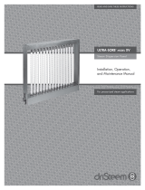
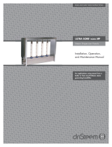
Normally-closed 597 SI with 46 in.
2
actuator shown
TI 597SI
TECHNICAL INSTRUCTIONS
Iron Body Series 597 SI
UTILITY IRON BODY CONTROL VALVES
®

Page 2 TI597SI
APPLICATION INFORMATION
Flowrite II Single Seated SI balanced valves are generally recommended for
steam, hot water and chilled water applications. They are particularly
suited for installations requiring tight shutoff and quick response.
THEORY OF OPERATION
On normally closed valve assemblies, the valve stem will start to open
whenever the control air pressure applied against the actuator diaphragm
area and the lower housing exceeds the holding force of the springs. A
further increase in control air pressure will initiate a continued upward
travel of the valve steam until the valve has fully opened.
On normally open valve assemblies, the stem will start to close whenever
the control air pressure applied against the actuator diaphragm area and
upper housing exceeds the holding force of the springs. A further increase
in control air pressure will initiate a continued downward travel of the
valve stem until the valve has fully closed.
The air pressure change to initiate full stem travel is known as the spring
range or span. This spring span is factory set and will vary slightly as the
pressure drop across the valve changes.
When the valve is at its’ “full open” position there is maximum flow
potential through the valve. At this position, valves are compared based
on flow that is directly related to the valve flow coefficient (see Cv
equations in table 1). The 597 SI valves are designed so that equal changes
in valve stem position provide equal percentage changes in existing flow
through the valve. This is otherwise know as an equal percent valve which
has a typical flow curve (figure 2) that can be used to determine flow based
on stem position, pressure drop, and Cv. As you can see from the graph,
these valves are less sensitive at the low end, which gives both high
rangeability and high flows. These types of valves are used extensively to
compensate for fluctuating system requirements (pressure, flow, load, etc.).
Valve actuators equipped with positioners provide feedback for enhanced
control strategies and, as an example, are required for valve staging. Valves
with positioners can utilize full control air pressure at any point in stem
travel to initiate stem movement or to maintain stem position. However,
the actuator springs still provide the necessary force to move the stem in
the opposite direction. Use of a positioner will tend to provide faster
response and ensure repeatability of stem position regardless of the load on
the actuator. However, in a system where available pressure and flow
requirements are relatively consistent, control valves can usually perform
adequately without a positioner.
Figure 1 A- Push to Open
Figure 1 B- Push to Close
Figure 2

TI597SI Page 3
VALVE SIZING AND SELECTION (WATER)
The sizing of a valve is very important if it is to render good service. If it
is "undersized", it will not have sufficient capacity. If it is “oversized”, the
controlled variable may cycle, the trim can be exposed to excessive wear or
wire drawing, and you could expect reduced valve life. To help select the
right valve, it is important to understand your application and its variables
(controlled fluid, temperatures, pressures, min/max load, etc.). When
your system variables are known and you have calculated actual demand, it
is possible to select the right Powers valve for your application. The
following technical data should help you in selecting a valve for your water
control applications. For fluid applications other than water, contact
Powers’ application engineering.
On/Off Control:
These types of applications are normally line sized to reduce pressure drop
and pump size. In these applications it is important to verify valve seat
leakage will not result in system overheat or damage. If this is a concern, it
is necessary to take precautions to alleviate this potential problem.
Proportional Control:
In applications where the close-off pressure at the valve is below 20psig,
use a pressure drop of 5psi.
In applications where the close-off pressure at the valve is above 20psig, it
is generally recommended to take 25-50% of the system pressure drop at
the control valve to maintain good valve/system performance. Certain
applications can successfully utilize lower pressure drops across the valve
(5-25%) if system fluctuations are kept to a minimum. If not, the valve is
considered oversized it will not effectively throttle until it is nearly closed
thereby resulting in poor control.
Refer to the following table for flow….
Table - 1 Water Capacity in Gallons Per Minute
Valve Cv
Size Rating Differential Pressure (
Δ
P in psi)
5 10 20 30 40 50 60 70 80 90 100 125
2.5 56 125 177 250 307 354 396 434 469 501 531 560 626
385190 269 380 466 538 601 658 711 760 806 850 950
4 145 324 459 648 794 917 1025 1123 1213 1297 1376 1450 1621
5 240 537 759 1073 1315 1518 1697 1859 2008 2147 2277 2400 2683
6 370 827 1170 1655 2027 2340 2616 2866 3096 3309 3510 3700 4137
CAVITATION LIMITATIONS ON VALVE PRESSURE DROP
A concern in high temperature water systems is the potential for cavitation/flashing, which is caused by the downstream pressure being lower than that of the
vapor pressure of the fluid. This basically causes the water to "boil" and can result in reduced flow/capacity, excessive noise, vibration, wear and should be
avoided if possible. Use the following equation to estimate the maximum allowable pressure drop across the valve:
Pmax = 0.5 (P1 – Pv)
Where:
Pmax = Maximum allowable pressure drop
P1 = Absolute inlet pressure (psia)
Pv = Absolute vapor pressure (refer to psia - Table 2)
Absolute pressure = gauge pressure + 14.7
Table-2 Vapor Pressure of Water Table
Water Vapor Water Vapor
Temp. Pressure Temp. Pressure
(
°
F) (psia) (
°
F) (psia)
40 0.12 140 2.89
50 0.18 150 3.72
60 0.26 160 4.74
70 0.36 170 5.99
80 0.51 180 7.51
90 0.70 190 9.34
100 0.95 200 11.53
110 1.28 210 14.12
120 1.69 220 17.19
130 2.22 230 20.78

Page 4 TI597SI
VALVE SIZING AND SELECTION (STEAM)
Steam:
One can use the same reasoning for selecting a valve in steam applications
as would be used for water applications. Once again, pressure drop
selection is a major determining factor for good control and system
performance. In general, for steam applications, the largest possible
pressure drop should be taken without exceeding the critical pressure ratio.
On/Off Control:
These types of applications are normally line sized to reduce pressure drop.
In these applications it is important to verify valve seat leakage will not
result in system overheat or damage. If this is a concern, it is necessary to
take precautions to alleviate this potential problem.
Proportional Control:
For pressures less than 15psig, use an 80% of the gauge inlet pressure as a
differential. For pressures above 15psig, use 42% of the absolute inlet
pressure. In those cases where the required Cv falls between two valves,
select the larger size.
One may be concerned about steam entering a heating coil at 0psig when
these large pressure drops are taken at the valve. However, flow will
continue as the pressure in the coil will drop to vacuum pressures due to
the steam condensation. It is essential to use proper condensate piping
and steam trapping in these applications.
Table - 3 Steam Capacity in Pounds Per Hour
Steam Inlet Pressure (psig)
25 10
Pressure Drop
Across Valve (psi) 0.5 1 2 1 2 3 4 5 2 4 6 8 10
Valve Cv
Size Rating
2.5 56 477 669 932 729 1017 1229 1399 1542 1145 1585 1898 2140 2334
385 724 1016 1415 1106 1544 1865 2124 2341 1738 2405 2880 3249 3543
4 145 1235 1733 2413 1887 2634 3182 3623 3993 2965 4103 4914 5542 6044
5 240 2044 2869 3994 3123 4359 5267 5997 6610 4907 6792 8133 9172 10004
6 370 3151 4423 6157 4815 6720 8120 9246 10190 7565 10471 12538 14141 15423
Steam Inlet Pressure (psig) 15 25 50
Pressure Drop
(max) (max) (max)
Across Valve (psi) 3 6 9 12 15 5 10 15 20 10 20 30 32.5
Valve Cv
Size Rating
2.5 56 1530 2105 2505 2805 3035 2268 3098 3655 4053 4064 5501 6422 6599
385 2322 3195 3802 4257 4607 3443 4702 5548 6152 6168 8350 9747 10017
4 145 3961 5450 6485 7262 7858 5873 8022 9464 10495 10522 14243 16628 17088
5 240 6556 9021 10734 12020 13007 9721 13277 15665 17372 17415 23575 27522 28284
6 370 10107 13908 16548 18531 20052 14986 20469 24150 26781 26489 36345 42430 43604

TI597SI Page 5
50
250
200
150
100
50
300
150
100
Pressure — psig
Temperature — °F
200
Maximum Media
Temperature
281°F
Minimum Media
Temperature
40°F
169 psig
597 SI
Figure 3 - Temperature and Pressure Ratings
TEMPERATURE/PRESSURE RATINGS
In all cases, do not exceed the temperature/pressure
ratings of the valve (see figure 3). Acceptable region is
shown by the shaded area.
Steam Inlet Pressure (psig) 75 100 125
Pressure Drop
(max)
Across Valve (psi) 10 20 30 40 45 10 20 30 40 50 10 20 30 40 50
Valve Cv
Size Rating
2.5 56 4840 6640 7873 8781 9146 5508 7610 9096 10236 11138 6104 8470 10172 11508 12595
385 7347 10079 11950 13329 13882 8361 11552 13806 15537 16906 9265 12857 15440 11467 19117
4 145 12533 17193 20386 22738 23681 14263 19706 23551 26504 28839 15805 21932 26339 29797 32611
5 240 20744 28457 33742 37635 39196 23607 32616 38981 43868 47734 26159 36302 43595 49320 53977
6 370 31980 43871 52018 58021 60426 36395 50283 60096 67630 73590 40329 55966 67209 76035 83215
Where:
W = Steam flow (lbs/hr)
Cv = Valve Flow Coefficient (US gpm with ΔP = psi)
K = 1+ (0.0007* ºF superheat)
P = Pressure differential, P1 - P2 (psi)
P1 = Inlet Pressure (psia)
P2 = Outlet pressure (psia)
Absolute Pressure = Gauge pressure + .7 (psia)
Δ

Page 6 TI597SI
Table - 5 Flange Detail for American Standard 125 lb. Cast Iron Pipe Flanges
Flanges Drilling Bolting Length of
Valve Flange Flange Diameter of Diameter of Number Diameter Machine
Size Diameter Thickness Bolt Circle Bolt Holes of Bolts of Bolts Bolts
AB C D E
2-1/2" 7" 11/16" 5-1/2" 3/4" 4 5/8" 2-1/2"
3" 7-1/2" 3/4" 6" 3/4" 4 5/8" 2-1/2"
4" 9" 15/16" 7-1/2" 3/4" 8 5/8" 3"
5" 10" 15/16" 8-1/2" 7/8" 8 3/4" 3"
6" 11" 1" 9-1/2" 7/8" 8 3/4" 3-1/4"
Figure 5
DIMENSIONAL DATA
Table-4 Dimensions for 597 SI Series Valves
Nominal Pipe Size 2-1/2" 3" 4" 5" 6" 6"
Normally Closed Normally Open
A 8.562 9.500 11.500 13.000 14.000
STROKE 1.000 1.000 1.000 1.000 1.750 1.750
B 4.000 4.232 4.923 5.934 6.226 7.461
C 4.302 4.927 5.754 6.763 7.479 6.339
D 10.375 10.375 10.375 10.375 N/A N/A
E 10.000 10.000 10.000 10.000 N/A N/A
F N/A N/A N/A N/A 19.000 19.000
G N/A N/A N/A N/A 10.313 10.313
Valve Weight (lbs) 46 58 95 141 146 146
Weight w/46” 65.00 78.00 103.00 152.00 N/A N/A
Weight w/100” N/A N/A N/A N/A 178.00 178.00
Figure 4 - 2-1/2” to 6” Valve Bodies
6" Valve
2-1/2" - 5" Valve

TI597SI Page 7
INSTALLATION
Inspection
Inspect the package for damage. If damaged, notify the appropriate carrier
immediately.
If undamaged, open the package and inspect the device for obvious
damage. Return damaged products.
Requirements
• Pipe wrenches
• Flange gaskets, bolts/nuts
• Installer must be a qualified, experienced technician
CAUTION!
• Install the valve with the flow in the direction of the flow arrow.
(“A”
port is the inlet and “AB” is the outlet.)
• Do not exceed the ratings of the device.
• Avoid locations where excessive moisture, corrosive fumes, or
vibration are present.
Mounting/Orientation
1. The valve should be mounted in a location that is within the
ambient limits of the actuator. When selecting a location, allow
sufficient room for valve linkage, actuator, and other accessories
and for service of the product.
2. The preferred mounting position for the valve is with the valve
stem vertical above the valve body. Avoid mounting the valve so
that the valve stem is below horizontal.
3. On steam applications where the ambient temperature
approaches the limit of the actuator, the valve stem should
bemounted 45° from vertical.
Flanged Connection
The 597SI series flanged valve bodies conform to American Standard 125
Lb. Cast Iron Pipe Flanges. The companion flanges (not provided) should
be the same specification as the valve. The 125 lb. flanges have plain flat
faces and should not be bolted to a raised faced flange.
1. All parts should be clean to assure the best results.
2. The pipe with the companion flanges installed should be
properly supported and aligned. Be sure the companion flange is
flush with the face of the valve body flange and lined up
squarely.
3. Use a gasket material (not provided) that is recommended for
the medium being handled.
CAUTION! Do not apply pipe dope to the valve flange, gasket,
or companion flange.
4. See Figure-5 for flange and flange bolt details.
Figure-6 shows the proper way a flanged valve should be
mounted.
MAINTENANCE
Regular maintenance of the total system is recommended to assure sustained performance. See Table-6 for maintenance kit part numbers.
Table - 6 Maintenance Kits for 597SI Valves
Valve Description Replacement Replacement Valve Repair Kit*
Packing Assembly Gaskets
2.5 Normally Closed 597 Pack 597250G 597 SIGOBCTK
3 Normally Closed 597300G 597 SIHOBCTK
4 Normally Closed 597400G 597 SIJOBCTK
5 Normally Closed 597500G 597 SIKOBCTK
6 Normally Closed 597600G 597 SILOBCTK
2.5 Normally Open 597250G 597 SIGOBXTK
3 Normally Open 597300G 597 SIHOBXTK
4 Normally Open 597400G 597 SIJOBXTK
5 Normally Open 597500G 597 SIKOBXTK
6 Normally Open 597600G 597 SILOBXTK
* Kit includes replacement packing and stem & plug assembly.
Water System Maintenance
All systems are susceptible to valve and system problems caused by improper
water treatment and system storage procedures. These guidelines are
provided to help avoid valve and water system problems resulting from
improperly treated water or storage procedures and to obtain maximum life
from the valves.
Durability of valve stems and packings is dependent on maintaining non-
damaging water conditions. Inadequate water treatment or filtration can
result in corrosion, scale, and abrasive particle formation. Scale and
particulates can result in stem and packing scratches and can adversely affect
packing life and other parts of the hydronic system.
To maintain non-damaging conditions, follow these guidelines:
• Clean the system prior to start up.
• Use filtration equipment where needed.
• Properly store off-line systems and monitor water treatment results.
• Follow the advice of a water treatment professional.
Valve
Body
Gasket:
Supplied
by Others
Companion
Flange
Figure 6 - Installation of
Flanged End Valves

I/P TRANSDUCERS
The “standard” 3-15 psi signal was originally designed as a transmission
signal, not a valve actuation signal. The Fluid Controls Institute (in
Standard 87-2) has recommended that a 1–17 psi air signal range be used
when directly actuating a control valve without a positioner. Powers
concurs with this recommendation, and therefore, offers a 1–17 psi I/P
transducer and a 0–30 psi I/P transducer and the Accritem pneumatic
controller for maximum close-off. 3-15 psi I/P transducers should be used
in conjunction with positioners.
POSITIONERS
Positioners are used for one or more of the following reasons:
1) To split range valves.
2) To eliminate unwanted valve movement caused by line pressure
variations
3) To minimize the effects of “stick-slip”
4) To speed response time
5) To increase close-off rating when I/Ps are used.
Page 8 TI597SI
CODE PNEUMATIC DIAPHRAGM ACTUATORS
4C 46 Sq. In., 1” Max Valve Stroke Extreme Cycle Springs,
adjustable start w/6-12 lb. fixed span.
1U (for 6" valve only) 100 Sq. In; 8-13 psi Spring Range, (Normally Closed Valves)
1L (for 6" valve only) 100 Sq. In; 3-8 psi Spring Range, (Normally Open Valves)
CODE DESCRIPTION
Bellofram 1000 I/P’S
IS 3–15 psi
TS 1–17 psi
US 3–27 psi
CONTROL/AIR TYPE 900X I/P
ES 0–30 psi
UTILITY POSITIONER AND I/P
BS 4–20 mA
UTILITY POSITIONER
PS 3-15 psi
RS 3-9 psi
SS 9-15 ps
NO ACCESSORIES
OS No Accessories
ACCESSORIES SELECT CODE
ACTUATOR SELECT CODE
ORDERING INFORMATION
© 2007 Powers
USA: Phone: 1.800.669.5430 • Fax 1. 847. 229 . 0526 • www.powerscontrols.com
Canada: Phone: 1.888.208.8927 • Fax 1.888.882.1979 • www.powerscontrols.ca
TI597SI 0708 EDP# 6512273
/