
IPAC
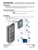
Introduction
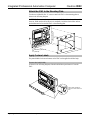
This document contains instructions for installing the IPAC series of wall-mounted,
Integrated Professional Automation Computers.
The IPAC is designed for installation in a standard 3-gang electrical box.
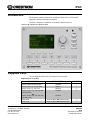
IPAC-GL1-W-T Physical View (shown in white)
Supplied Parts
The parts supplied with the IPAC are listed in the following table.
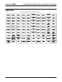
Supplied Hardware for the IPAC
DESCRIPTION PART NUMBER QUANTITY
Mounting Plate with Ground Wire 4506280 1
Screws, 06-32 x ¾”, Combo Head 2009211 4
Screws, 04-40 x ¼”, Pan, Phil 2007156 2
Screws, 04-40, 7/16", Pan, Phil, Blk
(for Black units)
OR
Screws, 04-40, 7/16", Pan, Phil, Zinc
(for White units)
2022900
2013409
4
Label Sheet
4505784 (Black) OR 4506570 (White)
1
Front Cover
4505711 (Black) OR 4505867 (White)
1
Crestron Electronics, Inc. Installation Guide – DOC. 6696A
15 Volvo Drive Rockleigh, NJ 07647 (2022187)
Tel: 888.CRESTRON 12.08
Fax: 201.767.7576 Specifications subject to
www.crestron.com change without notice.

Integrated Professional Automation Computer Crestron IPAC
Installation
The following tools are required for installation of an IPAC:
• Philips screwdriver
• Flat screwdriver; 3/32” (2.4 mm) blade size
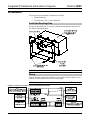
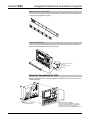
Install the Mounting Plate
Use the four included 06-32 x ¾” screws to install the mounting plate on the electrical
box. Refer to the diagram below.
NOTE: The ground wire from the mounting plate must be attached to an earth ground.
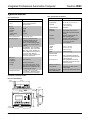
Wiring
Make the necessary connections as called out in the illustration below. Details for each
connector can be found below and on the following pages.
NOTE: Complete all other connections before wiring the 4-position NET connector.
Hardware Connections for the IPAC (Shown with Mounting Plate Attached)
2 • Integrated Professional Automation Computer: IPAC Installation Guide – DOC. 6696A

Crestron IPAC Integrated Professional Automation Computer
WARNING: Prior to connecting the IPAC, turn off power at the power supply. Failure
to do so may result in serious personal injury or damage to the device. Restore power
after all connections have been made.
When making connections to the IPAC, note the following:
• All terminals accept one 26-16 AWG wire.
• Use Crestron
®
power supplies for Crestron equipment.
NOTE: The IPAC can only be powered by either of the 4-position NET connectors.
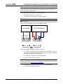
NET Connectors
Refer to the illustration below when wiring the NET connectors.
24 V
(RED)
GROU ND
(BLACK)
24 V
(RE D)
GROUND
(BLACK)
Z
(BLUE)
GLA-PWS50
Y
(WHITE)
NETWORK DEVICE
When wiring the NET connectors, consider the following:
• Use Crestron Certified Wire such as CRESNET-NP or CRESNET-P. Failure to
do so may incur additional charges if support is required to identify performance
deficiencies because of using improper wire.
• Use Crestron power supplies for Crestron equipment.
• Provide sufficient power to the system.
CAUTION: Insufficient power can lead to unpredictable results or damage to the
equipment. Please use the Crestron Power Calculator to help calculate how much power
is needed for the system (
www.crestron.com/calculators).
• For networks with 20 or more devices, use a Cresnet
®
Hub/Repeater
(CNXHUB) to maintain signal quality.
Installation Guide – DOC. 6696A Integrated Professional Automation Computer: IPAC • 3

Integrated Professional Automation Computer Crestron IPAC
LAN Connector
The following illustration shows the pin assignments of the RJ-45 LAN connector.
WARNING: Incorrect wiring may damage the IPAC.
GREEN
LED
YELLOW
LED
PIN 8
PIN 1
PIN SIGNAL PIN SIGNAL
1 TX + 5 N/C
2 TX - 6 RC -
3 RC+ 7 N/C
4 N/C 8 N/C
COM Connector
Refer to the illustration below when wiring the COM connector.
WARNING: Incorrect wiring may damage the IPAC.
RS-232 DEVICE
WITH HARDWARE
HANDSHAKING
RX TX G CTS RTS
RS-232 DEVICE
WITHOUT
HARDWARE
HANDSHAKING
RX TX G
4 • Integrated Professional Automation Computer: IPAC Installation Guide – DOC. 6696A

Crestron IPAC Integrated Professional Automation Computer
RELAYS Connector
Refer to the illustration below when wiring the RELAYS connector.
WARNING: Incorrect wiring may damage the IPAC.
INPUTS Connector
The illustration below is an example of what could be connected to the INPUTS
connector.
WARNING: Incorrect wiring may damage the IPAC.
Installation Guide – DOC. 6696A Integrated Professional Automation Computer: IPAC • 5

Integrated Professional Automation Computer Crestron IPAC
Attach the IPAC to the Mounting Plate
Use the two included 04-40 x ¼” screws to attach the IPAC to the mounting plate as
shown in the following diagram.
CAUTION: Excess wire that is pinched between the IPAC and the electrical box could
short out. Make sure that all excess wire is completely inside the electrical box and not
pinched between the box and the IPAC or the mounting plate.
SCREWS (2) 04-40 x ¼"
(2007156)
Apply Custom Labels
Pre-printed labels for the seven buttons on the IPAC can be applied to the label strip.
Remove the Label Holder
As shown in the following diagram, slide the label holder up and remove it from the
IPAC.
PUSH LABEL HOLDER UP
AND PULL AWAY FROM THE
IPAC
6 • Integrated Professional Automation Computer: IPAC Installation Guide – DOC. 6696A

Crestron IPAC Integrated Professional Automation Computer
Affix Labels to the Label Holder
As shown in the following diagram, attach labels to the label holder. The included labels
are shown in the appendix on page 11.
Install the Label Holder
As shown in the following diagram, attach the label holder by placing the holder tabs in
the slots and sliding them downward into position.
PLACE LABEL HOLDER TABS
IN SLOTS.
SLIDE TABS DOWN TO
SECURE IT.
Attach the Faceplate to the IPAC
Use the included 04-40, 7/16” screws to attach the faceplate to the IPAC as shown in the
following diagram.
AFTER ATTACHING FACEPLATE,
VERIFY FACEPLATE PLACEMENT BY PUSHING
ALL BUTTONS TO ENSURE SMOOTH OPERATION.
IF ANY BUTTONS STICK, LOOSEN SCREWS,
REPOSITION FACEPLATE AND RETIGHTEN SCREWS.
SCREWS (4) 04-40 x
7
16
"
(2022900 or 2013409)
Installation Guide – DOC. 6696A Integrated Professional Automation Computer: IPAC • 7

Integrated Professional Automation Computer Crestron IPAC
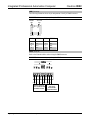
Specifications
IPAC Specifications
SPECIFICATION DETAILS
Processor
CPU
32-bit Freescale ColdFire
®
Microprocessor
Memory
SDRAM
NVRAM
Flash
Power Failure
Memory
32 MB
1 MB
8 MB
10 years
Time Clock Accuracy ±1 minute per year
Operating System Real-time, preemptive multi-
threaded/multitasking kernel;
FAT32 file system with long
names; includes default program
for Green Light Power Switching
systems
Ethernet 10/100BASE-T, auto-negotiating,
full/half duplex, static IP or DHCP,
DNS, SSL, TCP/IP, UDP/IP, CIP,
SMTP, SNMP, built-in Web server
and e-mail client; supports
Crestron e-Control
®
2 XPanel and
RoomView
®
applications.
IR Receiver
Reception
Frequency
Formats
Range
36 to 38 kHz IR
Crestron format, RC5
Up to 50 feet (15 meters) line of
sight typical, dependent on angle,
obstructions, IR interference and
IR remote signal strength
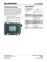
Power Requirements 10 Watts (0.42 A @ 24 VDC);
GLA-PWS50 or equivalent power
supply required (sold separately)
(Continued on following column)
IPAC Specifications (Continued)
SPECIFICATION DETAILS
Environmental
Temperature
Humidity
Heat Dissipation
32º to 104 º F (0 º to 40 º C)
10% to 90% RH
(non-condensing)
20 BTU/Hr
Enclosure
Faceplate
Chassis
Mounting
High-impact plastic, black or
white, with polycarbonate label
overlay
Injection-molded plastic with
steel mounting plate
Requires 3-gang plaster ring or
electrical box (not included),
≥ 2.5 in (6.4 cm) deep
recommended
Dimensions
Height
Width
Depth
4.50 in (115 mm)
6.70 in (171 mm)
2.24 in (57 mm)
Weight 1.32 lbs (0.60 kg)
Available Models
IPAC-GL1-B-T
IPAC-GL1-W-T
IPAC Integrated Professional
Automation Computer for Power
Switching (Black)
IPAC Integrated Professional
Automation Computer for Power
Switching (White)
Available Accessories
GLA-PWS50
MP/MPC/IPAC_FRO
NT_LABEL-[B,W]-T
Wall Mount 50 Watt Cresnet
Power Supply
Set of Engravable Backlit Labels
IPAC Overall Dimensions
4.50 in
(115 mm)
5.25 in
(134 mm)
0.40 in
(11 mm)
6.70 in
(171 mm)
0.33 in
(9 mm)
6.04 in
(154 mm)
2.24 in
(57 mm)
0.85 in
(22 mm)
8 • Integrated Professional Automation Computer: IPAC Installation Guide – DOC. 6696A

Integrated Professional Automation Computer Crestron IPAC
Industry Compliance
This unit has been manufactured to comply with UL’s Standards for Safety in Canada
and the United States. Formal approval is pending.
As of the date of manufacture, the IPAC has been tested and found to comply with
specifications for CE marking.
NOTE: This device complies with part 15 of the FCC rules. Operation is subject to the
following two conditions: (1) this device may not cause harmful interference and (2) this
device must accept any interference received, including interference that may cause
undesired operation.
This equipment has been tested and found to comply with the limits for a Class B digital
device, pursuant to part 15 of the FCC Rules. These limits are designed to provide
reasonable protection against harmful interference in a residential installation. This
equipment generates, uses and can radiate radio frequency energy and if not installed and
used in accordance with the instructions, may cause harmful interference to radio
communications. However, there is no guarantee that interference will not occur in a
particular installation. If this equipment does cause harmful interference to radio or
television reception, which can be determined by turning the equipment off and on, the
user is encouraged to try to correct the interference by one or more of the following
measures:
Reorient or relocate the receiving antenna.
Increase the separation between the equipment and receiver.
Connect the equipment into an outlet on a circuit different from that to which the
receiver is connected.
Consult the dealer or an experienced radio/TV technician for help.
9 • 3-Phase Power Loss Sensor: IPAC Installation Guide – DOC. 6696A

Integrated Professional Automation Computer Crestron IPAC
Problem Solving
Troubleshooting
The following table provides corrective action for possible trouble situations. If further
assistance is required, please contact a Crestron customer service representative.
IPAC Troubleshooting
TROUBLE POSSIBLE CAUSE(S) CORRECTIVE ACTION
Display is dark. Power is not present. Verify that power is properly connected to the
IPAC.
For issues encountered during operation, refer to the latest version of the IPAC-GL1
Setup Guide (Doc. 6660) which can be downloaded from the Crestron website
(www.crestron.com/manuals).
Reference Documents
The latest version of all documents mentioned within the guide can be obtained from the
Crestron website (
www.crestron.com/manuals). This link will provide a list of product
manuals arranged in alphabetical order by model number.
List of Related Reference Documents
DOCUMENT TITLE
IPAC Setup Guide
Further Inquiries
If you cannot locate specific information or have questions after reviewing this guide,
please take advantage of Crestron's award winning customer service team by calling the
Crestron corporate headquarters at 1-888-CRESTRON [1-888-273-7876].
You can also log onto the online help section of the Crestron website
(
www.crestron.com/onlinehelp) to ask questions about Crestron products. First-time
users will need to establish a user account to fully benefit from all available features.
10 • Integrated Professional Automation Computer: IPAC Installation Guide – DOC. 6696A

Crestron IPAC Integrated Professional Automation Computer
Appendix
The following labels are included with the IPAC:
Installation Guide – DOC. 6696A 3-Phase Power Loss Sensor: IPAC • 11

Integrated Professional Automation Computer Crestron IPAC
Return and Warranty Policies
Merchandise Returns / Repair Service
1. No merchandise may be returned for credit, exchange or service without prior authorization from
CRESTRON. To obtain warranty service for CRESTRON products, contact an authorized
CRESTRON dealer. Only authorized CRESTRON dealers may contact the factory and request an
RMA (Return Merchandise Authorization) number. Enclose a note specifying the nature of the
problem, name and phone number of contact person, RMA number and return address.
2. Products may be returned for credit, exchange or service with a CRESTRON Return Merchandise
Authorization (RMA) number. Authorized returns must be shipped freight prepaid to
CRESTRON, 6 Volvo Drive, Rockleigh, N.J. or its authorized subsidiaries, with RMA number
clearly marked on the outside of all cartons. Shipments arriving freight collect or without an RMA
number shall be subject to refusal. CRESTRON reserves the right in its sole and absolute
discretion to charge a 15% restocking fee plus shipping costs on any products returned with an
RMA.
3. Return freight charges following repair of items under warranty shall be paid by CRESTRON,
shipping by standard ground carrier. In the event repairs are found to be non-warranty, return
freight costs shall be paid by the purchaser.
CRESTRON Limited Warranty
CRESTRON ELECTRONICS, Inc. warrants its products to be free from manufacturing defects in materials and
workmanship under normal use for a period of three (3) years from the date of purchase from CRESTRON,
with the following exceptions: disk drives and any other moving or rotating mechanical parts, pan/tilt heads and
power supplies are covered for a period of one (1) year; touchscreen display and overlay components are
covered for 90 days; batteries and incandescent lamps are not covered.
This warranty extends to products purchased directly from CRESTRON or an authorized CRESTRON dealer.
Purchasers should inquire of the dealer regarding the nature and extent of the dealer's warranty, if any.
CRESTRON shall not be liable to honor the terms of this warranty if the product has been used in any
application other than that for which it was intended or if it has been subjected to misuse, accidental damage,
modification or improper installation procedures. Furthermore, this warranty does not cover any product that
has had the serial number altered, defaced or removed.
This warranty shall be the sole and exclusive remedy to the original purchaser. In no event shall CRESTRON
be liable for incidental or consequential damages of any kind (property or economic damages inclusive) arising
from the sale or use of this equipment. CRESTRON is not liable for any claim made by a third party or made by
the purchaser for a third party.
CRESTRON shall, at its option, repair or replace any product found defective, without charge for parts or labor.
Repaired or replaced equipment and parts supplied under this warranty shall be covered only by the unexpired
portion of the warranty.
Except as expressly set forth in this warranty, CRESTRON makes no other warranties, expressed or implied,
nor authorizes any other party to offer any warranty, including any implied warranties of merchantability or
fitness for a particular purpose. Any implied warranties that may be imposed by law are limited to the terms of
this limited warranty. This warranty statement supersedes all previous warranties.
Trademark Information
All brand names, product names and trademarks are the sole property of their respective owners. Windows is a registered trademark of
Microsoft Corporation. Windows95/98/Me/XP/Vista and WindowsNT/2000 are trademarks of Microsoft Corporation.
12 • Integrated Professional Automation Computer: IPAC Installation Guide – DOC. 6696A
-
 1
1
-
 2
2
-
 3
3
-
 4
4
-
 5
5
-
 6
6
-
 7
7
-
 8
8
-
 9
9
-
 10
10
-
 11
11
-
 12
12


Crestron IPAC-GL1 User manual
- Type
- User manual
- This manual is also suitable for
Ask a question and I''ll find the answer in the document
Finding information in a document is now easier with AI
Related papers
-
Crestron Green Light IPAC-GL1 User manual
-
-
-
-
-
-
-
-
-
Other documents
-
 Crestron electronic GLA-PWS50 User manual
-
 Crestron electronic 120 Volt User manual
-
Mettler Toledo ReactIR 45m User manual
-
PAC Computer Accessories GM3 User manual
-
ICP DAS USA I-87H17W User manual
-
Ametek IPAC User manual
-
-
-
-
Dynex DX-IPAC User manual

