Page is loading ...

TORO SNOW COMMANDER SERVICE MANUAL
Table of Contents – Page 1 of 2
GENERAL INFORMATION
INTRODUCTION
ENGINE
IDENTIFICATION AND ORDERING
GENERAL SAFETY INSTRUCTIONS (REPRODUCED FROM OPERATOR'S MANUAL
SAFETY
SAFE OPERATING PRACTICES
TRAINING
PREPARATION
OPERATION
MAINTENANCE AND STORAGE
TORO SNOWTHROWER SAFETY
SAFETY AND INSTRUCTION DECALS
FUEL AND OIL REQUIREMENTS
MIXING GASOLINE AND OIL
FILLING THE FUEL TANK
OFF-SEASON STORAGE
EMPTYING THE FUEL TANK
STORAGE
PREPARING THE FUEL SYSTEM
PREPARING THE ENGINE
PREPARING THE SNOWTHROWER
CONTROLS LOCATION & OPERATION
OPERATING CONTROLS
STARTING THE ENGINE
STOPPING THE ENGINE
STARTING THE ROTOR BLADES
STOPPING THE ROTOR BLADES
STARTING THE TRACTION DRIVE
STOPPING THE TRACTION DRIVE
ADJUSTING THE DISCHARGE CHUTE
CHUTE HANDLE
CHUTE CRANK
UPPER SHROUD REMOVAL
SNOW COMMANDER CHUTE HANDLE SYSTEM
CHUTE CRANK SYSTEM
GEAR LASH ADJUSTMENT
GEAR ASSEMBLY REPAIR
ENGINE REMOVAL / INSTALLATION
ASSEMBLY
RECOIL STARTER ACCESS
ASSEMBLY

TORO SNOW COMMANDER SERVICE MANUAL
Table of Contents – Page 2 of 2
DRIVE SYSTEM
OPERATION
DRIVE SYSTEM DISASSEMBLY
DRIVE SYSTEM ASSEMBLY
ROTOR BEARING REPLACEMENT
ASSEMBLY
ROTOR CABLE REPLACEMENT
ELECTRIC START SYSTEM
OPERATION
TROUBLESHOOTING
SYSTEM DISASSEMBLY
ASSEMBLY
SWITCH BOX REPAIR
POWER PLUG
PLUG TERMINAL
SWITCH
MOTOR TESTING
ASSEMBLY
STARTER PINION REPLACEMENT
ASSEMBLY
CHASSIS
WHEELS AND TIRES
TILT MECHANISM/FRAME
PIVOT CABLE REPLACEMENT
MAINTENANCE
RECOMMENDED MAINTENANCE SCHEDULE
ROTOR CONTROL CABLE
CHECKING THE ROTOR CONTROL CABLE
ADJUSTING THE ROTOR CONTROL CABLE
ADJUSTING THE PIVOT CABLE
CHECKING THE PIVOT CABLE
ADJUSTING THE PIVOT CABLE
REPLACING THE ROTOR BLADES
REMOVING THE OLD ROTOR BLADES
INSTALLING THE NEW ROTOR BLADES
REPLACING THE SCRAPER
REPLACING THE SPARK PLUG
REPLACING THE DRIVE BELT
CHECKING THE TIRE PRESSURE
TROUBLESHOOTING
SPECIFICATIONS (GENERAL)
TORQUE SPECIFICATIONS
LUBRICATION

TORO
®
Snow Commander
Service Manual

ABOUT THIS MANUAL
This service manual was written expressly for Toro servicing dealers. The Toro Company
has made every effort to make the information in this manual complete and correct.
This manual was written with the assumption that the reader has basic mechanical
knowledge and skills. This book contains material covering the Toro Snow Commander
models produced in 2001 and 2002, and may be specified for use on products built after
2002 that are similar in design.
We hope you find this manual a valuable addition to your service shop. If you have
questions or comments regarding this manual, please contact us at the following address:
The Toro Company
Consumer Service Department
8111 Lyndale Avenue South
Bloomington, MN 55420-1196
The Toro Company reserves the right to change product specifications or this manual
without notice.
Copyright© All Rights Reserved
©2001 The Toro Company

Snow Commander Service Manual i
TABLE OF CONTENTS
GENERAL INFORMATION
Introduction . . . . . . . . . . . . . . . . . . . . . . . . . . . . . . . . . . . . . . . . . . . . . . . . . . . . . . . . . . .1 - 1
Engine . . . . . . . . . . . . . . . . . . . . . . . . . . . . . . . . . . . . . . . . . . . . . . . . . . . . . . . . . . . . . . .1 - 1
Identification and Ordering . . . . . . . . . . . . . . . . . . . . . . . . . . . . . . . . . . . . . . . . . . . . . . .1 - 2
General Safety Instructions (Reproduced from Operator’s Manual) . . . . . . . . . . . . . . . .1 - 2
Safety . . . . . . . . . . . . . . . . . . . . . . . . . . . . . . . . . . . . . . . . . . . . . . . . . . . . . . . . . . . . . . .1 - 3
Safe Operating Practices . . . . . . . . . . . . . . . . . . . . . . . . . . . . . . . . . . . . . . . . . . . . . .1 - 3
Training . . . . . . . . . . . . . . . . . . . . . . . . . . . . . . . . . . . . . . . . . . . . . . . . . . . . . . . . . . .1 - 3
Preparation . . . . . . . . . . . . . . . . . . . . . . . . . . . . . . . . . . . . . . . . . . . . . . . . . . . . . . . . .1 - 3
Operation . . . . . . . . . . . . . . . . . . . . . . . . . . . . . . . . . . . . . . . . . . . . . . . . . . . . . . . . . .1 - 3
Maintenance and Storage . . . . . . . . . . . . . . . . . . . . . . . . . . . . . . . . . . . . . . . . . . . . .1 - 4
Toro Snowthrower Safety . . . . . . . . . . . . . . . . . . . . . . . . . . . . . . . . . . . . . . . . . . . . . . . .1 - 4
Safety and Instruction Decals . . . . . . . . . . . . . . . . . . . . . . . . . . . . . . . . . . . . . . . . . .1 - 5
Fuel and Oil Requirements . . . . . . . . . . . . . . . . . . . . . . . . . . . . . . . . . . . . . . . . . . . . . . .1 - 6
Mixing Gasoline and Oil . . . . . . . . . . . . . . . . . . . . . . . . . . . . . . . . . . . . . . . . . . . . . . .1 - 6
Filling the Fuel Tank . . . . . . . . . . . . . . . . . . . . . . . . . . . . . . . . . . . . . . . . . . . . . . . . . .1 - 7
Off-Season Storage . . . . . . . . . . . . . . . . . . . . . . . . . . . . . . . . . . . . . . . . . . . . . . . . . . . . .1 - 7
Emptying the Fuel Tank . . . . . . . . . . . . . . . . . . . . . . . . . . . . . . . . . . . . . . . . . . . . . . .1 - 7
Storage . . . . . . . . . . . . . . . . . . . . . . . . . . . . . . . . . . . . . . . . . . . . . . . . . . . . . . . . . . . .1 - 7
Preparing the Fuel System . . . . . . . . . . . . . . . . . . . . . . . . . . . . . . . . . . . . . . . . . . . . .1 - 8
Preparing the Engine . . . . . . . . . . . . . . . . . . . . . . . . . . . . . . . . . . . . . . . . . . . . . . . . .1 - 8
Preparing the Snowthrower . . . . . . . . . . . . . . . . . . . . . . . . . . . . . . . . . . . . . . . . . . . .1 - 8
CONTROLS LOCATION & OPERATION
Operating Controls . . . . . . . . . . . . . . . . . . . . . . . . . . . . . . . . . . . . . . . . . . . . . . . . . . . . .2 - 1
Starting the Engine . . . . . . . . . . . . . . . . . . . . . . . . . . . . . . . . . . . . . . . . . . . . . . . . . . . . .2 - 1
Stopping the Engine . . . . . . . . . . . . . . . . . . . . . . . . . . . . . . . . . . . . . . . . . . . . . . . . . . . .2 - 1
Starting the Rotor Blades . . . . . . . . . . . . . . . . . . . . . . . . . . . . . . . . . . . . . . . . . . . . . . . .2 - 2
Stopping the Rotor Blades . . . . . . . . . . . . . . . . . . . . . . . . . . . . . . . . . . . . . . . . . . . . . . . .2 - 2
Starting the Traction Drive . . . . . . . . . . . . . . . . . . . . . . . . . . . . . . . . . . . . . . . . . . . . . . . .2 - 2
Stopping the Traction Drive . . . . . . . . . . . . . . . . . . . . . . . . . . . . . . . . . . . . . . . . . . . . . . .2 - 2

TABLE OF CONTENTS
ii Snow Commander Service Manual
CONTROLS LOCATION & OPERATION (cont’d)
Adjusting the Discharge Chute . . . . . . . . . . . . . . . . . . . . . . . . . . . . . . . . . . . . . . . . . . . . 2 - 2
Chute Handle . . . . . . . . . . . . . . . . . . . . . . . . . . . . . . . . . . . . . . . . . . . . . . . . . . . . . . 2 - 2
Chute Crank . . . . . . . . . . . . . . . . . . . . . . . . . . . . . . . . . . . . . . . . . . . . . . . . . . . . . . . 2 - 3
Upper Shroud Removal . . . . . . . . . . . . . . . . . . . . . . . . . . . . . . . . . . . . . . . . . . . . . . 2 - 3
Snow Commander Chute Handle System . . . . . . . . . . . . . . . . . . . . . . . . . . . . . . . . 2 - 3
Chute Crank System . . . . . . . . . . . . . . . . . . . . . . . . . . . . . . . . . . . . . . . . . . . . . . . . . 2 - 4
Gear Lash Adjustment . . . . . . . . . . . . . . . . . . . . . . . . . . . . . . . . . . . . . . . . . . . . . . . . . . 2 - 5
Gear Assembly Repair . . . . . . . . . . . . . . . . . . . . . . . . . . . . . . . . . . . . . . . . . . . . . . . 2 - 5
ENGINE REMOVAL / INSTALLATION
Assembly . . . . . . . . . . . . . . . . . . . . . . . . . . . . . . . . . . . . . . . . . . . . . . . . . . . . . . . . . 3 - 4
Recoil Starter Access . . . . . . . . . . . . . . . . . . . . . . . . . . . . . . . . . . . . . . . . . . . . . . . . 3 - 5
Assembly . . . . . . . . . . . . . . . . . . . . . . . . . . . . . . . . . . . . . . . . . . . . . . . . . . . . . . . . . 3 - 6
DRIVE SYSTEM
Operation . . . . . . . . . . . . . . . . . . . . . . . . . . . . . . . . . . . . . . . . . . . . . . . . . . . . . . . . . 4 - 1
Drive System Disassembly . . . . . . . . . . . . . . . . . . . . . . . . . . . . . . . . . . . . . . . . . . . . 4 - 2
Drive System Assembly . . . . . . . . . . . . . . . . . . . . . . . . . . . . . . . . . . . . . . . . . . . . . . 4 - 4
Rotor Bearing Replacement . . . . . . . . . . . . . . . . . . . . . . . . . . . . . . . . . . . . . . . . . . . 4 - 5
Assembly . . . . . . . . . . . . . . . . . . . . . . . . . . . . . . . . . . . . . . . . . . . . . . . . . . . . . . . . . 4 - 6
Rotor Cable Replacement . . . . . . . . . . . . . . . . . . . . . . . . . . . . . . . . . . . . . . . . . . . . . 4 - 6
ELECTRIC START SYSTEM
Operation . . . . . . . . . . . . . . . . . . . . . . . . . . . . . . . . . . . . . . . . . . . . . . . . . . . . . . . . . . . . 5 - 1
Troubleshooting . . . . . . . . . . . . . . . . . . . . . . . . . . . . . . . . . . . . . . . . . . . . . . . . . . . . 5 - 1
System Disassembly . . . . . . . . . . . . . . . . . . . . . . . . . . . . . . . . . . . . . . . . . . . . . . . . . 5 - 1
Assembly . . . . . . . . . . . . . . . . . . . . . . . . . . . . . . . . . . . . . . . . . . . . . . . . . . . . . . . . . . . . 5 - 2
Switch Box Repair . . . . . . . . . . . . . . . . . . . . . . . . . . . . . . . . . . . . . . . . . . . . . . . . . . . 5 - 3
Power Plug . . . . . . . . . . . . . . . . . . . . . . . . . . . . . . . . . . . . . . . . . . . . . . . . . . . . . . . . 5 - 3
Plug Terminal . . . . . . . . . . . . . . . . . . . . . . . . . . . . . . . . . . . . . . . . . . . . . . . . . . . . . . 5 - 3
Switch . . . . . . . . . . . . . . . . . . . . . . . . . . . . . . . . . . . . . . . . . . . . . . . . . . . . . . . . . . . . 5 - 4
Motor Testing . . . . . . . . . . . . . . . . . . . . . . . . . . . . . . . . . . . . . . . . . . . . . . . . . . . . . . 5 - 4
Assembly . . . . . . . . . . . . . . . . . . . . . . . . . . . . . . . . . . . . . . . . . . . . . . . . . . . . . . . . . . . . 5 - 4
Starter Pinion Replacement . . . . . . . . . . . . . . . . . . . . . . . . . . . . . . . . . . . . . . . . . . . 5 - 5
Assembly . . . . . . . . . . . . . . . . . . . . . . . . . . . . . . . . . . . . . . . . . . . . . . . . . . . . . . . . . . . . 5 - 6
CHASSIS
Wheels and Tires . . . . . . . . . . . . . . . . . . . . . . . . . . . . . . . . . . . . . . . . . . . . . . . . . . . 6 - 1
Tilt Mechanism/Frame . . . . . . . . . . . . . . . . . . . . . . . . . . . . . . . . . . . . . . . . . . . . . . . 6 - 1
Pivot Cable Replacement . . . . . . . . . . . . . . . . . . . . . . . . . . . . . . . . . . . . . . . . . . . . . 6 - 2

Snow Commander Service Manual iii
TABLE OF CONTENTS
MAINTENANCE
Recommended Maintenance Schedule . . . . . . . . . . . . . . . . . . . . . . . . . . . . . . . . . . . . . .7 - 1
Rotor Control Cable . . . . . . . . . . . . . . . . . . . . . . . . . . . . . . . . . . . . . . . . . . . . . . . . . . . . .7 - 1
Checking the Rotor Control Cable . . . . . . . . . . . . . . . . . . . . . . . . . . . . . . . . . . . . . . .7 - 1
Adjusting the Rotor Control Cable . . . . . . . . . . . . . . . . . . . . . . . . . . . . . . . . . . . . . . .7 - 2
Adjusting the Pivot Cable . . . . . . . . . . . . . . . . . . . . . . . . . . . . . . . . . . . . . . . . . . . . . . . .7 - 3
Checking the Pivot Cable . . . . . . . . . . . . . . . . . . . . . . . . . . . . . . . . . . . . . . . . . . . . . .7 - 3
Adjusting the Pivot Cable . . . . . . . . . . . . . . . . . . . . . . . . . . . . . . . . . . . . . . . . . . . . . .7 - 4
Replacing the Rotor Blades . . . . . . . . . . . . . . . . . . . . . . . . . . . . . . . . . . . . . . . . . . . . . . .7 - 4
Removing the Old Rotor Blades . . . . . . . . . . . . . . . . . . . . . . . . . . . . . . . . . . . . . . . . .7 - 4
Installing the New Rotor Blades . . . . . . . . . . . . . . . . . . . . . . . . . . . . . . . . . . . . . . . . .7 - 5
Replacing the Scraper . . . . . . . . . . . . . . . . . . . . . . . . . . . . . . . . . . . . . . . . . . . . . . . . . . .7 - 6
Replacing the Spark Plug . . . . . . . . . . . . . . . . . . . . . . . . . . . . . . . . . . . . . . . . . . . . . . . .7 - 6
Replacing the Drive Belt . . . . . . . . . . . . . . . . . . . . . . . . . . . . . . . . . . . . . . . . . . . . . . . . .7 - 7
Checking the Tire Pressure . . . . . . . . . . . . . . . . . . . . . . . . . . . . . . . . . . . . . . . . . . . . . . .7 - 9
Troubleshooting . . . . . . . . . . . . . . . . . . . . . . . . . . . . . . . . . . . . . . . . . . . . . . . . . . . . . . . .7 - 9
Specifications (General) . . . . . . . . . . . . . . . . . . . . . . . . . . . . . . . . . . . . . . . . . . . . . . . .7 - 11
Torque Specifications . . . . . . . . . . . . . . . . . . . . . . . . . . . . . . . . . . . . . . . . . . . . . . . . . .7 - 11
Lubrication . . . . . . . . . . . . . . . . . . . . . . . . . . . . . . . . . . . . . . . . . . . . . . . . . . . . . . . . . . .7 - 11

iv Snow Commander Service Manual
THIS PAGE INTENTIONALLY LEFT BLANK

Snow Commander Service Manual 1 - 1
GENERAL INFORMATION
Introduction
Read this manual carefully to learn how to operate and
maintain your product properly. The information in this
manual can help you and others avoid injury and
product damage. Although Toro designs and produces
safe products, you are responsible for operating the
product properly and safely.
Engine
The Toro Snow Commanders are powered by a high
output version of the R tek engine (Figure 1). The main
difference between the standard R tek and the version
used on the Snow Commander is in the piston and
cylinder.
The piston has two additional square ports (Figure 2),
which line up with two grooves machined in the
cylinder wall (Figure 3). As the piston goes down and
compresses the fuel/air charge in the crankcase, the
ports in the piston uncover the grooves in the cylinder
wall. This provides extra area for the fuel charge to
move to the firing chamber. The result is a larger fuel
charge, which makes more power.
Figure 1
DSC-0138
Figure 2 DSC-0037
Figure 3 DSC-0032
All service procedures and techniques are the same as
those on the other R tek engines. See E Engine
Service Manual, Form #492-0647.
(A) Ports
(A) Grooves
A
A

GENERAL INFORMATION
1 - 2 Snow Commander Service Manual
Identification and Ordering
Whenever you need service, genuine Toro parts, or
additional information, contact an Authorized Service
Dealer or Toro Customer Service and have the model
and serial numbers of your product ready. Figure 1
illustrates the location of the model and serial numbers
on the product.
Figure 4
m-5045
Provide the full model and serial number to any
Authorized Toro Service Dealer. They will be able to
look up the part number and provide you with price
quotes and availability. The factory does not sell parts
or products direct.
Should you wish to obtain your own parts catalog or a
replacement owners manual, they can be obtained
from the factory.
Be prepared to supply the complete model and serial
number and contact us at the following address:
The Toro Company
8111 Lyndale Ave. S.
Bloomington, MN 55420
Phone: 1-800-348-2424
Follow the instructions to contact the parts dept. The
parts department staff will be happy to assist you in
obtaining replacement manuals.
General Safety Instructions
(Reproduced from Operator’s Manual)
This manual identifies potential hazards and has
special safety messages that help you and others
avoid personal injury and even death. Danger,
Warning, and Caution are signal words used to
identify the level of hazard. However, regardless of the
hazard, be extremely careful.
Danger signals an extreme hazard that will cause
serious injury or death if you do not follow the
recommended precautions.
Warning signals a hazard that may cause serious
injury or death if you do not follow the recommended
precautions.
Caution signals a hazard that may cause minor or
moderate injury if you do not follow the recommended
precautions.
This manual uses two other words to highlight
information. calls attention to special
mechanical information and Note: emphasizes general
information worthy of special attention.
(A) Location of the model and serial numbers
Important

Snow Commander Service Manual 1 - 3
GENERAL INFORMATION
Safety
To ensure maximum safety and best performance,
and to gain knowledge of the product, it is
essential that you and any other operator of the
snowthrower read and understand the contents of
this manual before the engine is ever started.
This is the safety alert symbol. It is used to
alert you to potential personal injury hazards. Obey
all safety messages that follow this symbol to
avoid possible injury or death.
Improperly using or maintaining this snowthrower
could result in injury or death. To reduce this
potential, comply with the following safety
instructions.
Safe Operating Practices
The following instructions have been adapted from the
ANSI/OPEI B71.3–1995 standard and the ISO
8437:1989 standard. Information or terminology
specific to Toro snowthrowers is enclosed in
parenthesis.
Training
• Read the operator’s manual carefully. Be thoroughly
familiar with the controls and the proper use of the
equipment. Know how to stop the unit and
disengage the controls quickly.
• Never allow children to operate the snowthrower.
Never allow adults to operate the snowthrower
without proper instruction.
• Keep the area of operation clear of all persons
(particularly small children) and pets.
• Exercise caution to avoid slipping or falling.
Preparation
• Thoroughly inspect the area where you will use the
snowthrower. Remove all doormats, sleds, boards,
wires, and other foreign objects.
• Release the control bar to disengage the rotor
blades before starting the engine.
• Do not operate the snowthrower without wearing
adequate winter garments. Wear footwear that will
improve your footing on slippery surfaces.
• Handle fuel with care; it is highly flammable.
– Use an approved fuel container.
– Never add fuel to a running or hot engine.
– Fill the fuel tank outdoors with extreme care.
Never fill the fuel tank indoors.
– Replace the fuel tank cap securely and wipe up
any spilled fuel.
• Use only the power cord supplied with the
snowthrower and a receptacle appropriate for use
with the power cord for electric-start motors.
• Never attempt to make any adjustments while the
engine is running, except where specifically
recommended by Toro.
• Let the engine and the snowthrower adjust to the
outdoor temperature before starting to clear snow.
• Operating any powered machine can result in
foreign objects being thrown into the eyes. Always
wear safety glasses or eye shields while operating,
adjusting, or repairing the snowthrower.
Operation
• Do not put hands or feet near or under rotating
parts. Keep clear of the discharge opening at all
times.
• Exercise extreme caution when crossing gravel
drives, walks, or roads. Stay alert for hidden
hazards or traffic.
• Do not attempt to clear snow from a crushed-rock or
gravel surface. This product is intended for use only
on paved surfaces.
• After striking a foreign object, stop the engine,
remove the ignition key, thoroughly inspect the
snowthrower for any damage, and repair the
damage before operating the snowthrower.
• If the unit should start to vibrate abnormally, stop
the engine and check immediately for the cause.
Vibration is generally a warning of trouble.
• Stop the engine whenever you leave the operating
position, before unclogging the discharge chute,
and when making any repairs, adjustments, or
inspections.
• When cleaning, repairing, or inspecting, make
certain that the rotor blades and all moving parts
have stopped.

GENERAL INFORMATION
1 - 4 Snow Commander Service Manual
• Do not run the engine indoors, except when starting
it and for moving the snowthrower in or out of the
building. Open the outside doors; exhaust fumes
are dangerous.
• Do not clear snow across the face of slopes.
Exercise extreme caution when changing direction
on slopes. Do not attempt to clear steep slopes.
• Never operate the snowthrower without proper
guards, plates, or other safety protective devices in
place.
• Never operate the snowthrower near glass
enclosures, automobiles, window wells, and drop-
offs without properly adjusting the snow discharge
angle. Keep children and pets away.
• Do not overload the machine capacity by attempting
to clear snow at too fast a rate.
• Look behind and use care when backing up with the
snowthrower.
• Never direct the discharge at bystanders or allow
anyone in front of the unit.
• Never operate the snowthrower without good
visibility or light. Always be sure of your footing, and
keep a firm hold on the handle. Walk; never run.
Maintenance and Storage
• Check all fasteners at frequent intervals for proper
tightness to be sure that the equipment is in safe
working condition.
• Never store the machine with fuel in the fuel tank
inside a building where ignition sources are present,
such as hot water and space heaters and clothes
dryers. Allow the engine to cool before storing in
any enclosure.
• Always refer to this operator’s manual for important
details if the snowthrower is to be stored for an
extended period.
• Maintain or replace safety and instruction labels
when necessary.
Toro Snowthrower Safety
The following list contains safety information specific to
Toro products or other safety information that you must
know.
• Rotating rotor blades can injure fingers or hands.
Stay behind the handles and away from the
discharge opening while operating the snowthrower.
Keep your face, hands, feet, and any other part of
your body or clothing away from moving or rotating
parts.
• Before adjusting, cleaning, repairing, and inspecting
the snowthrower, and before unclogging the
discharge chute, stop the engine, remove the key,
and wait for all moving parts to stop.
• Use a stick, not your hands, to remove obstructions
from the discharge chute.
• Before leaving the operating position, stop the
engine, remove the key, and wait for all moving
parts to stop.
• Do not wear loose-fitting clothing that could get
caught in moving parts.
• If a shield, safety device, or decal is damaged,
illegible, or lost, repair or replace it before beginning
operation.
• Also, tighten any loose fasteners.
• Do not smoke while handling gasoline.
• Do not use the snowthrower on a roof.
• Do not touch the engine while it is running or soon
after it has stopped because the engine may be hot
enough to cause a burn.
• Perform only those maintenance instructions
described in this manual. Before performing any
maintenance, service, or adjustment, stop the
engine, remove the key. If major repairs are ever
needed, contact your Authorized Service Dealer.
• Do not change the governor settings on the engine.
• When storing the snowthrower for more than 30
days, drain the fuel from the fuel tank to prevent a
potential hazard. Store fuel in an approved fuel
container. Remove the key from the ignition switch
before storing the snowthrower.
To ensure the best performance and safety, purchase
only genuine Toro replacement parts and accessories.

Snow Commander Service Manual 1 - 5
GENERAL INFORMATION
Safety and Instruction Decals
Safety decals and instructions are easily visible to the operator and are located near any area of
potential danger. Replace any decal that is damaged or lost.
104-2767
104-4135
104-2775
104-0863 (Electric-start model only)
104-0874
104-4125
61-4790 (Electric-start model only)
104-4106 (Recoil-start model only)

GENERAL INFORMATION
1 - 6 Snow Commander Service Manual
Fuel and Oil Requirements
Mixing Gasoline and Oil
This Toro snowthrower is powered by a two-cycle
engine that requires a 50:1 gasoline-to-oil mixture.
Use only clean, unleaded gasoline no more than 30
days old and with an octane rating of 87 or higher.
Using unleaded gasoline reduces combustion chamber
deposits and promotes longer spark plug life.
Engines certified to comply with U.S. EPA emission
regulations for ULGE engines are certified to operate
on a mixture of regular unleaded gasoline and oil, include
the following emission control system(s): EM and TWC (if
equipped), and do not include any user-adjustable features.
Do not use methanol, gasoline
containing methanol, gasohol containing more than
10% ethanol, premium gasoline, or white gas. Using
these fuels can damage the fuel system.
Do not use an automotive oil (such as
SAE 30 or 10W30), a two-cycle oil that is not NMMA
TCW-certified, or a fuel mixed at the wrong gasoline-to-
oil ratio. This can cause engine damage not covered
under the Toro warranty.
Note: Use a fuel stabilizer/conditioner for all Toro
gasoline-powered products during operation and
storage. A fuel stabilizer/conditioner cleans the engine
during operation and prevents gum-like varnish
deposits from forming in the engine during storage. A
fuel stabilizer/conditioner works best when you mix it
with fresh gasoline. If you use Toro 50:1 2-Cycle Oil
(Fuel Stabilizer Added), you do not need to add a fuel
stabilizer/conditioner.
Do not use fuel additives except a fuel
stabilizer during storage. Do not use fuel stabilizers
with an alcohol base, such as ethanol, methanol, or
isopropanol.
1. Pour a half gallon (1.9 liters) of fresh, unleaded
gasoline into an approved fuel container.
Note: Do not mix gasoline and oil in the fuel tank. Oil at
room temperature mixes easier and more thoroughly
than cold oil. Oil below 32°F (0°C) requires additional
mixing.
DANGER
In certain conditions, gasoline is extremely
flammable and highly explosive. A fire or
explosion from gasoline an burn you and others
and cause property damage.
• Fill the fuel tank outdoors, in an open area,
and when the engine is cold. Wipe up any
gasoline that spills.
• Do not fill the fuel tank completely full. Add
gasoline to the fuel tank until the level is 1/4
to 1/2 in. (6 to 13mm) below the bottom of the
filler neck. This empty space in the tank
allows the gasoline to expand.
• Never smoke when handling gasoline, and
stay away from an open flame or where a
spark may ignite gasoline fumes.
• Store gasoline in an approved fuel container
and keep it out of the reach of children.
• Never buy more than a 30-day supply of
gasoline.
Important
Important
DANGER
When fueling under certain circumstances, a
static charge can develop igniting the gasoline.
A fire or explosion from gasoline can burn you
and other and damage property.
• Always place gasoline containers on the
ground and away from your vehicle before
filling.
• Do not fill gasoline containers inside a
vehicle or on a truck or trailer bed because
interior carpets or plastic truck bed liners
may insulate the container and slow the loss
of any static charge.
• When practical, remove gas-powered
equipment from the truck or trailer and refuel
the equipment with its wheels on the ground.
• If this is not possible, then refuel such
equipment on a truck or trailer from a
portable container, not from a gasoline
dispenser nozzle.
• If you must use a gasoline dispenser nozzle,
keep the nozzle in contact with the rim of the
fuel tank or container opening at all times
until fueling is complete.
Important

Snow Commander Service Manual 1 - 7
GENERAL INFORMATION
2. Add the full amount of Toro 50:1 2-Cycle Oil (Fuel
Stabilizer Added) or an equivalent high grade,
NMMA TCW-certified two-cycle oil to the gasoline
according to the chart below:
3. Install the cap on the fuel container.
4. Shake the container to mix the gasoline and oil
thoroughly.
5. Slowly remove the cap and add the remaining
amount of gasoline.
Filling the Fuel Tank
Do not overfill the fuel tank. The
gasoline-and-oil mixture must have room to expand.
1. Clean around the fuel tank cap; do not allow snow
or water to enter the fuel tank.
2. Remove the fuel tank cap and fill the fuel tank with
the gasoline-and-oil mixture until the level is 1/4 to
1/2 in. (6 to 13mm) below the bottom of the filler
neck. Do not fill into the filler neck.
3. Install the fuel tank cap securely and wipe up any
spilled fuel.
Off-Season Storage
Emptying the Fuel Tank
1. Stop the engine and wait for all moving parts to
stop.
2. Remove the key from the switch.
3. Remove the fuel tank cap and use a hand pump to
pump the fuel into an approved fuel container.
4. Start the engine and allow it to run until it stops.
Repeat this step two more times to ensure that the
fuel tank and the carburetor are empty.
Storage
Store the snowthrower in its operating
position and on its wheels. Storing the snowthrower on
its front housing may cause hard starting.
50:1 Gasoline-to Oil Ration Mixing Chart
Gasoline Oil
1 gallon (4 liters) 2.6 ounces (80 ml)
2 gallons (8 liters) 5.2 ounces (160 ml)
5 gallons (20 liters) 13 ounces (400 ml)
Important
DANGER
Gasoline is highly flammable; it can ignite and
cause serious personal injury.
• Drain gasoline outdoors.
• Drain gasoline from a cold engine only.
• Wipe up any gasoline that may have spilled.
• Do not drain gasoline near any open flame or
where gasoline fumes may be ignited by a
spark.
• Do not smoke a cigar, a cigarette, or a pipe
when handling gasoline.
WARNING
Gasoline fumes are highly flammable, explosive,
and dangerous if inhaled. If you store the
product in an area with an open flame, the
gasoline fumes may ignite and cause an
explosion.
Do not store the snowthrower in a house (living
area), basement, or any other area where
ignition sources may be present, such as hot
water and space heaters, clothes dryers,
furnaces, and other like appliances.
Important

GENERAL INFORMATION
1 - 8 Snow Commander Service Manual
Preparing the Fuel System
1. Add a fuel stabilizer/conditioner to the fuel in the
fuel tank as directed.
NOTE: If you use Toro 50:1 2-Cycle (Fuel Stabilizer
Added), you do not need to add a fuel stabilizer/
conditioner.
2. Run the engine for five minutes to distribute the
conditioned fuel through the fuel system.
3. Stop the engine, allow it to cool.
4. Use a hand pump to pump the fuel from the fuel
tank into an approved fuel container, or run the
engine until it stops.
5. Start the engine and run it until it stops.
6. Choke or prime the engine, start it a third time,
and run the engine until it will not start.
7. Dispose of unused fuel properly. Recycle it
according to local codes, or use it in your
automobile.
Note: Do not store stabilized fuel for more than 90
days.
Preparing the Engine
Follow this procedure to prevent cylinder bore
corrosion by closing both the intake and exhaust ports
of the engine.
1. Slowly pull the recoil starter until you feel
resistance due to compression pressure, then
stop.
2. Release the starter tension gradually by allowing
the rope to go back slowly to prevent the engine
from reversing due to compression pressure.
Preparing the Snowthrower
1. Tighten all loose screws, bolts, and locknuts.
Repair or replace any damaged parts.
2. Clean the snowthrower thoroughly.
3. Cover the snowthrower and store it in a clean, dry
place out of the reach of children. Allow the engine
to cool before storing it in any enclosure.

Snow Commander Service Manual 2 - 1
CONTROLS LOCATION & OPERATION
NOTE: Determine the left and right sides of the
machine from normal operating position.
Operating Controls
The snowthrower control panel contains a key switch, a
primer, a recoil starter, and an electric-start button
(electric-start model only). The choke lever and the
cord connection (for the electric-start model) are
located below the control panel as show in Figure 5.
Figure 5
m-5067
Starting the Engine
1. Turn the key to the On position.
2. Move the choke lever to the right.
3. Cover the hole in the center of the primer with
your thumb and push the primer in twice, pausing
a moment between pushes. In extremely cold
temperatures, repeat this step if necessary.
Note: Take off your glove when you push in the
primer so that air cannot escape from the primer
hole.
Note: Do not use the choke or the primer when
starting a warm engine.
4. Start the engine by doing the following:
For a recoil starter: Hold the snowthrower handle
with one hand and pull the recoil starter vigorously
with the other hand.
For an electric starter:
A. Connect the power cord to the snowthrower
and to a standard household power outlet.
B. Push the starter button.
Note: Run the electric starter no more than
ten times at intervals of five seconds on, then
five seconds off.
Running the electric starter extensively
can overheat and damage the starter.
Note: If the engine does not start after this
series of attempts, wait at least 40 minutes to
allow the starter to cool before attempting to
start it again.
5. With the engine running, move the choke lever to
the left slowly.
Stopping the Engine
Turn the key to the Off position and wait for all moving
parts to stop before leaving the operating position.
(A) Key switch
(B) Primer
(C) Electric-start button (electric-start model only)
(D) Recoil start
(E) Cord connection (electric-start model only;
underneath the control panel)
(F) Choke lever
CAUTION
If you leave the snowthrower plugged into a
power outlet, someone can inadvertently start
the snowthrower and injure people or damage
property.
Unplug the power cord whenever you are not
starting the snowthrower.
Important

CONTROLS LOCATION & OPERATION
2 - 2 Snow Commander Service Manual
Starting the Rotor Blades
To start the rotor blades, squeeze the control bar
toward the handle until the snowthrower begins to
pivot.
Stopping the Rotor Blades
To stop the rotor blades, release the control bar.
Note: When you release the control bar, the rotor
blades stop, but the engine continues to run.
Starting the Traction Drive
To start the traction drive, slowly squeeze the control
bar toward the handle. The front of the snowthrower
pivots downward. When the rotor blades touch the
ground, the snowthrower begins to move forward.
Squeezing the control bar completely to the handle
provides maximum traction.
Note: The traction is most aggressive (the traction
speed is fastest) when the rotor blades are new. If you
want to reduce the aggressiveness of the traction, refer
to "Adjusting the Pivot Cable" on page 7 - 3.
Stopping the Traction Drive
To stop the traction drive, partially release the control
bar until the rotor blades lift off the ground, disengaging
the traction drive. Releasing the control bar completely
stops both the traction drive and the rotor blades.
Adjusting the Discharge Chute
Chute Handle
On models equipped with a manual chute, move the
chute handle left and right to adjust the direction of the
snow stream (Figure 6). The chute deflector handle on
top of the discharge chute controls the height of the
snow stream. Do not overtighten the chute deflector
mounting locknuts.
Figure 6
m-5052
Do not use the chute handle to lift the
snowthrower. This can damage both the chute handle
and the snowthrower.
(A) Chute deflector mounting locknut (2)
(B) Chute deflector handle
(C) Chute handle
Important

Snow Commander Service Manual 2 - 3
CONTROLS LOCATION & OPERATION
Chute Crank
On models equipped with a chute crank, crank
clockwise to rotate the chute to the right,
counterclockwise to rotate the chute to the left (Figure
7). The chute deflector on these models is the same
as on models with a chute handle.
Figure 7
0621-0073
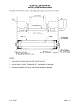
Upper Shroud Removal
The first step in many service procedures will be
removing the upper shroud for access to the engine.
Remove the three Phillips head screws, washer, and
locknuts that hold the chute and chute handle to the
chassis (Figure 8).
Remove two Phillips head screws, 4 washers, and 2
locknuts that secure the front corners of the upper
shroud (Figure 8).
Figure 8
3428-0216
Remove two 5/16” screws that hold the control panel to
the chassis (Figure 9).
Figure 9
3428-0217
Remove the fuel cap, lift the upper shroud off, and
replace the fuel cap.
Snow Commander Chute Handle System
Some Snow Commander models were equipped with a
manual chute system. As with the others, the
component parts are all plastic to eliminate the need for
lubrication and reduce icing.
(A) 2 Phillips Head
Screws, Washers,
and Locknuts
(B) 3 Phillips Head
Screws, Washers,
and Locknuts
A
B
A

CONTROLS LOCATION & OPERATION
2 - 4 Snow Commander Service Manual
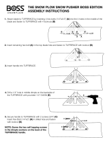
On this version, the discharge chute attaches to the
handle and chute ring. Three Phillips head bolts, nuts,
and washers connect the parts. Below the upper
shroud is the balance of the chute components.
Remove the upper shroud to access the chute ring, the
2 chute ring retainers, and the detent spring and arm
(Figure 10). To remove the chute ring, remove the four
bolts and nuts that retain the left and right chute ring
retainers.
Figure 10
1854-40
NOTE: The rear bolt in the left hand chute ring retainer
is also the pivot for the detent arm. This arm engages
the notches in the chute ring to prevent unwanted
movement. With the 4 bolts removed, the retainers and
chute ring will lift off.
Reassembly is the reverse of disassembly.
Chute Crank System
The chute crank handle goes through hole in the
control panel support (Figure 11).
Figure 11
3428-0082
Rotating the handle turns a set of gears that engage a
ring gear that the chute is mounted to. The gears are
contained in a bracket located under the upper shroud.
The chute ring gear rests on a support and is held in
place by two retainers.
To access the chute ring and gears:
1. Remove the upper shroud.
2. The gears are held in the bracket by a shaft with a
push nut on either end (Figure 12). To remove the
shaft, remove one of the push nuts and pull the
shaft out.
Figure 12
1854-19
(A) Spring
(B) Detent Arm
(C) Retainer Mounting Bolts
A
B
C
(A) Control Handle Support
(A) Shaft and Push Nut
A
A
/