Page is loading ...

FEATURES:
• 5 or 8 MegaPixel [4K] Network Camera (2592x1944px / 3840x2160px @ 30/25fps)
• 1/2.8” 5.69 / 8.29 MegaPixel Sony STARVIS CMOS® Sensor,
• ONVIF Compliant with Zero Configuration, ONVIF Event Mapping
• Cross Web Browsing (IE, Edge, Safari, Firefox, Chrome)
• Adaptive web-based resizing (Layout / Display Device Resolution Dependent)
• Quad Streaming: H.265, H.264 & MJPEG
• HTML5 Playback
• MicroSD Memory Card Slot Supporting Local Recording up to 128GB (H.264)
• ICR Dual Filter Switch
• CS mount supported (Option: C-mount adaptor)
• 120dB Dynamic Range with DOL (Digital Overlap) WDR @30/25fps
• Improved Noise Reduction with XD-DNR
• LDC (Lens Distortion Compensation)
• Smart Stream, RoI (Region of Interest)
- Enables Smart Processing of Video Data According to Users’ Needs
- Enables High Quality Video on RoI and Lower Quality Video on non-RoI
- Lowers Overall Bandwidth and Reduces Storage Burden
• Motion Detection, Privacy Masking, Defog, D-Zoom (~10x), Mirror/Flip,
Sens-up (Slow shutter), Hue, Contrast, Brightness / Saturation, Sharpness
• IP68 (VTD-MV8NZ311P, VTD-MV5NZ212P, VTC-IR8NZ4311P),
IP67 (VTC-IR5NZ3212P)
• Circuit Protection Protects Against Faulty Connection in Power Polarity
• Isolated Power Supply Protects Against Ground Loop Problems
• 12VDC, 24VAC and PoE Operation (Power over Ethernet, EEE Std. 802.3af)
Virtuoso Series
Virtuoso Series 5 and 8
MegaPixel Network Cameras
QUICK START GUIDE
*Lens Sold Separately
VTD-MV8NZ311P
VTD-MV5NZ212P
VTC-IR5NZ3212P
VTC-IR8NZ4311P
VTC-CB5N
VITEK
VITEK

Table of Contents
Safety Precautions.............................................. 3-4
Overview: VTC-IR5NZ3212P.............................. 5-9
Overview: VTC-IR8NZ4311P............................. 10-18
.
Overview: VTD-MV5NZ212P, VTD-MV8NZ311P................ 19-26
Overview: VTC-CB5N....................................... 27-29
OPERATING INSTRUCTIONS......................... 30-38
Menu Table / Network Menu Setup....... 30-32
Live View............................................... 33
Information............................................ 34
Users..................................................... 35
Date and Time...................................... 36-37
Network................................................ 38
Firmware Upgrade............................... 39
Detailed Specications..................................... 40-44
Accessories....................................................... 45
Warranty Information........................................ 46
2 3

CAUTION: TO REDUCE THE RISK OF ELECTRIC SHOCK,
DO NOT REMOVE COVER (OR BACK).
NO USER SERVICEABLE PARTS INSIDE.
REFER SERVICING TO QUALIFIED SERVICE PERSONNEL.
To prevent electric shocks and risk of fire hazards, do NOT expose this unit to rain
or use other than with the specified power source.
Warning :
This equipment has been tested and found to comply with the limits for a Class
A digital device, pursuant to part 15 of the FCC Rules. These limits are designed
to provide reasonable protection against harmful interference when the equipment
is operated in a commercial environment. This equipment generates, uses, and
can radiate radio frequency energy and, if not installed and used in accordance with
the instruction manual, may cause harmful interference to radio communications.
Operation of this equipment in a residential area is likely to cause harmful
interference in which case the user will be required to correct the interference at
his own expense.
Caution :
Any changes or modifications in construction of this device which are not expressly
approved by the party responsible for compliance could void the user's authority
to operate the equipment.
Mains power quality should be that of a typical commercial environment. If the user
of the model requires continued operation during power mains interruptions, it is
recommended that the model be powered from an uninterruptible power supply
(UPS) or a battery.
The symbol is intended to alert the user to the presence of important
operating and maintenance(servicing) instructions in the literature
accompanying the unit.
The symbol is intended to alert the user to the presence of uninsulated
"dangerous voltage" within the product's enclosure that may be of
sufficient magnitude to constitute a risk of electric shock to persons.
Safety Precautions
3

Safety Precautions
NOTICE
• The images used in this instruction manual are processed to help comprehension
and may differ from actual video of the camera.
• Avoid installing in areas where there shock or vibration which results in problems.
• Pay attention to safety when laying the connection cable and observe that the cable
is not subjected to heavy loads, kinks or damage and no moisture can get in.
• Never open the device such as boards or lens.
The warranty becomes void if repairs are undertaken by unauthorized persons.
• Maintenance and repair have to be carried out only by authorized service centers.
• Use only a mild detergent to clean the housing body only but never for the clear
bubble dome.
• The camera should never be operated beyond the technical specifications.
This can lead to destruction.
• The camera should never be operated in water.
4 5

MEGA-PIXEL NETWORK CAMERA
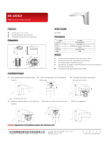
Composition - VTC-IR5NZ3212P
Dimensions - VTC-IR5NZ3212P
unit : inches / (mm)
Wiring Connector
(1pc)
Torque Wrench:
.12” 3mm (1pc)
Mounting Screw:
4 x 1.58” 40mm (3pcs)
Plastic Anchor:
6 x 1.181” 30mm (3pcs)
Mounting Template
Quick Start Guide
Camera
3.43 (87)
3.73 (94.8)
3.17 (80.5)
9.29 (236)
9.72 (247)
Ø3.64 (92.4)
5

Part Names - VTC-IR5NZ3212P
DUAL WINDOW
SUNSHIELD BOLT
SUNSHIELD
FRONT CASE
BRACKET
REAR CASE
Cover Open
Micro
SD Card Slot
IP Reset
Button
• Extreme care should be taken NOT to scratch the surface of window while
installing or adjusting the camera.
• Care should be taken so the cable is NOT damaged, kinked or exposed in
a hazardous area.
• Do not expose the camera directly to a strong light source such as the sun or
a spotlight.
CAUTION
POWER
CABLE
6 7

Installation Instructions
Mounting Screw
4x 1.58” (40mm)
1. Position the mounting template at the installation location and drill the ceiling
or wall if needed.
2. Route the cable and connect according to instructions below.
3. Place the camera bracket on the pre-drilled position and attach it using
mounting screws (4x40mm).
4. Set the camera’s viewing angle.
5. Put the sunshield on the camera unit and tighten the sunshield-bolt.
Pan & Tilt adjustments
1) Pan limit:
Pan is limited to +/- 90°.
2) Tilt limit:
Tilt is limited to 0°(2°) min ~ 90° max.
for wall (ceiling) installation respectively
with reference to the wall (ceiling) when
the inclination of camera module is 0°,
that is, the image is aligned horizontally.
90° 90°
• Unlock the screw on the camera bracket using the torque wrench
supplied.
• Set the camera’s viewing angle then lock the screw on the bracket.
7

Installation Instructions
Installation Instructions
• Make sure the power is removed before installation.
• After all connections are properly finished, follow the order for applying power.
a) Plug the network cable into RJ-45 Ethernet Port.
If PoE is the only power, there is no need to connect power terminal.
b) When DC12V or AC24V local power is necessary, connect the low voltage
(DC12V or AC24V) first, then plug the AC adapter to AC outlets to avoid an
improper reset from a power spike and damage from the voltage surge with
no load.
When PoE and local dual power are connected at the same time,
local power has priority.
Adjustment of viewing angle
with one-touch 3-Axis bracket
Torque
wrench
Lock/Unlock
Screw
3) Inclination limit
(Horizontal image alignment):
Inclination limited to +/-90° max.
90°
90°
±90°
• on the wall • on the ceiling
8 9

06
Installation Instructions
MEGA-PIXEL NETWORK CAMERA
Power Supply Connections
This camera can work with either 24AC or 12VDC, dual voltage power and PoE
(IEEE Std. 802.3af). Primary and secondary grounds are completely isolated
to avoid possible ground loop problems.
Ethernet
POWER
(AC24V/DC12V)
AC(-) :
AC24V/GND
AC(+) :
AC24V/DC12V
AC
(+)
AC
(-)
9

Composition VTC-IR8NZ4311P
Dimension VTC-IR8NZ4311P
unit : inches / mm
Torque Wrench:
.12” (3mm) (1pc)
Cable tie (2pcs)
Hinge pin (1pc)
Mounting
Template
Quick
Start
Guide
Camera unit
Mounting Screw:
4 x 1.18” (30mm) (4pcs)
Plastic Anchor:
6 x 1.18” (30mm) (4pcs)
Grommet (2pcs)
Cable Plate
with Screw
RJ45 Easy Cap
for Grommets
7.34 (186.5)
2.03 (51.50)
11.81 (300)
1.22 (31.00)
3.39 (86.15)
4.35 (110.50)
3.39 (86.15)
3.53 (89.60)
4.30 (109.19)
5.14 (130.50)
10 11

Part Names - VTC-IR8NZ4311P
[ JUNCTION BOX BOTTOM ]
Ethernet from Cam.
User Network
Network wiring
Connector
Junction Box
Open Alarm
Power & I/O
to Cam.
Power/ Alarm/ Audio
COVER OPEN
IP Reset (Default) : pressing for 5~8 seconds resets
all parameters to original factory settings.
Micro
SD Card Slot
LED Control Switch
SUNSHIELD BOLT
SUNSHIELD
DUAL
WINDOW
FRONT CASE
BRACKET
JUNCTION BOX TOP
JUNCTION BOX
BOTTOM
LOCK / UNLOCK
SCREW
11

Installation Instructions
Cover Opening Alarm and External Alarm Input are electrically tied
together internally.
Alarm contact types, N.O or N.C are selectable by the Alarm Input Selection
Jumper and the selection types should be matched with Alarm Type in setup
menu.
When both the Cover Opening Alarm and External Alarm Input are used at the
same time, the alarm contact types must match. Otherwise, the alarm malfunctions.
When only the External Alarm Input is used with disabling Cover Opening Alarm,
remove the jumper cap of Alarm Input Selection Jumper.
Default setting for Alarm Input selection jumper is N.C. It prevents the Alarm from
generating when Junction box is OPEN during installation. The alarm Input
selection jumper should be set to N.O and Event Trigger/Action should be
denied to enable Cover opening alarm.
For Cover Opening Alarm, please go to SETUP> Event Rules> Event Processing>
Add Event Trigger should be set to “Alarm In” an Event Action should be
set from the available options.
• Cover Opening Alarm and External Alarm Input :
CAUTION
N.O : Alarm is generated when Junction box is OPEN.
N.C : Alarm is generated when Junction box is CLOSED.
[N.O] [N.C]
Cover opening alarm switch
Alarm Input selection jumper
12 13

Installation Instructions
• Using Grommet :
Tear off the grommet caps and pull up the grommet so that the seal
can
wrap arund the cable properly as illustrated. If it doesn’t wrap properly,
it could cause water leakage problems.
3
2
1
• Using RJ45 Easy Cap for Network cable :
• Recommended cable length into the Junction box base :
- CABLE with RJ-45 Connector: 2.76~3.15”
- CABLE for Network Wiring Connector:
.79~1.18”
(excluding cable tripping section)
8P cable stripping distance: .79~1.18”
- Power CABLE: .79~1.18”
(excluding cable tripping section)
8P cable stripping distance: .79~1.18”
13

Installation Instructions
70~80mm
20~30mm20~30mm
20~30mm20~30mm
1
3
Locate the mounting template at the installation position and drill the wall if
needed.
Route the Power/Ethernet cables through the grommets from the wall.
Insert the grommets into the Junction box base.
Place the Junction box base on the pre-drilled position and attach it using
mounting screws (4 x 1.18” [30mm]).
Install the mount onto a strong structure.
Prepare the junction box base and the accessories for installation.
2
.79~1.18”.79~1.18”
.79~1.18”.79~1.18”
2.76~3.15”
14 15

Installation Instructions
1
2
4
5
3
6
7
8
TIA/EIA 568 A
1. Green-White
2. Green
3. Orange-White
4. Blue
5. Blue-White
6. Orange
7. Brown-White
8. Brown
TIA/EIA 568 B
1. Orange-White
2. Orange
3. Green-White
4. Blue
5. Blue-White
6. Green
7. Brown-White
8. Brown
Hook up the Power & I/O wires and Network cable to the connectors.
Network cable can be connected to either RJ-45 connector or LSA connectors.
4
5
4
5
Attach the cable plate and tie
the cable to it.
15

Installation Instructions
* Caution:
If screws are not firmly
assembled, it could
cause water leakage.
6
7
9
Cover the Junction box top and
tighten with assembly screws.(4pcs)
Set Alarm Input Selection Jumper.
(Refer to ‘Cover Opening Alarm
and External Alarm Input’ section)
Junction Box Top
Hinge pin
Assemble the Junction box top to the Junction box base using a hinge pin.
Hinge can be inserted at either side for convinience.
Connect the Power/Ethernet cables from camera.
16 17

Installation Instructions
Set the camera’s orientation and tighten the Lock/Unlock screws using
hex wrench.
Open the side cover to insert the Micro SD memory or control the Zoom /
Focus using the joystick.
After adjusting the settings, close the side cover and tighten it.
Put the sunshield on the camera unit and tighten the sunshield bolt.
Adjustment of viewing angle with a bracket
• Extreme care should be taken NOT to scratch the surface of window during
camera installation or adjusment.
• Care should be taken so the cable is NOT damaged, kinked or exposed in
a hazardous area.
• Do not expose the camera directly to a strong light source such as the sun or
a spotlight.
CAUTION
Hex
wrench
17

Installation Instructions
• Unlock the screw on the camera bracket using the hex wrench supplied.
• Set the camera’s viewing angle then lock the screw on the bracket.
Pan & Tilt adjustments
1) Pan limit:
Pan is limited to +/- 90°.
3) Inclination limit
(Horizontal image alignment):
Inclination limited to +/-90° max.
2) Tilt limit:
Tilt is limited to 0°(2°) min ~ 90° max.
for wall (ceiling) installation respectively
with reference to the wall (ceiling) when
the inclination of the camera module is 0°,
that is, the image is aligned horizontally.
90° 90°
88°
90°
±90°
• on the wall • on the ceiling
18 19

Composition -
VTD-MV5NZ212P / VTD-MV8NZ311P
Torque Wrench:
Plastic Anchor:
6 x 1.18” (30mm) (4pcs)
Mounting Screw:
4 x 1.18” (30mm) (4pcs)
Dome Camera
Connector Screw:
Cable Signal
Sticker
Wiring Connector
(1pc)
Mounting
Template
Quick
Start
Guide
Video Sub-out
Cable (1pc)
Assembly Screw:
Surface mount
Conduit Spacer &
Conduit hole cap(1set)
.16 x .55” (4 x 14mm) (3pcs)
.1” x .24” (2.6 x 6mm) (1pc)
.12” (3mm) (1pc)
19

unit: inches / mm
Dimensions VTD-MV5NZ212P / VTD-MV8NZ311P
Ø5.51 (140)
Ø3.93 (100)
4.69 (119)
Ø4.02 (102)
Ø5.51 (140)
2.64 (67)
4.69 (119)
1.46 (37)
3.23 (82)
[ Flush mount ] [ Surface mount ]
PCD Ø4.72 (120)
3-Ø.17 (4.2)
20 21
/