Page is loading ...

BLODGETT OVEN COMPANY
www.blodgettcorp.com
50 Lakeside Avenue, Box 586, Burlington, Vermont 05402 USA Telephone (800) 331-5842, (802) 860-3700 Fax: (802)864-0183
PN M4194 Rev A (2/00)
E 2000 --- G.S. Blodgett Corporation
MT3240E AND MT3240G
CONVEYOR OVENS
INSTALLATION -- OPERATION -- MAINTENANCE
MT3240E ET MT3240G
FOURS À BANDE TR ANSPORTEUSE
MANUEL D’INSTALLATION -- FONCTIONNEMENT -- ENTRETIEN

Your Service Agency’s Address:
Adressedevotreagencedeservice:
Model/Modèl:
Serial Number/Numéro de série:
Your oven wa s installed by/
Installateur de votre four:
Your oven’s installation was checked by/
Contrôleur de l’installation de votre four:

Table of Contents/Table des Matières
Introduction
Oven Description and Specifications 2....
Oven Components 3....................
Installation
Delivery and Inspection 4...............
Oven Location and Ventilation 5..........
Oven Assembly 6......................
Oven Supports and Casters 6..........
Stacking the Ovens 6..................
Conveyor Belt Support 7...............
Conveyor Belt 8......................
Conveyor Belt Tensioner 10.............
Crumb Pans 10........................
Optional Remote Computer Control 10...
Utility Connections ---
Standards and Codes 11.................
Gas Connection 12......................
Electrical Connection 15.................
Operation
Safety In formation 16....................
Cooking Computer 17...................
Oven Adjustments for Cooking 19.........
Maintenance
Cleaning 20............................
Box Component Locations 23.............
Troubleshooting Guide 25................
Introduction
Description et Spécifications du Four 28....
Éléments du Four 29.....................
Installation
Livraison et Inspection 31................
Implantation et aération du four 32........
Montage du Four 33.....................
LesSupportsduFouretlesRoulettes 33.
Superposition des Fours 33.............
Support de Bande Transporteuse 34.....
La Bande Transporteuse Métallique 35...
Tendeurs du Tapis 37...................
Plateaux pour Miettes 37...............
L’Ordinateur de Cuisson Détaché 37.....
Branchements de Service --- Normes et
Codes 38...............................
Branchement de Gaz 39.................
Raccordement Électrique 42..............
Utilisation
Informations de Sécurité 43...............
L’Ordinateur de Cuisson 44...............
Réglages du Four Pour la Cuisson 46......
Entretien
Nettoyage 47...........................
Emplacements des composants du boîtier de
commande 50..........................
GuidedeDétectiondesPannes 52........

Introduction
2
Oven Description and Specifications
Cooking in a conveyor oven differs from cooking
ina conventionaldeck orrangeovensinceheated
air is constantly recirculated over the product by
afaninanenclosedchamber. Themovingaircon-
tinually strips away the layer of cool air surround-
ingthe product, quicklyallowing theheat topene-
trate. The result is a high quality product, cooked
at alower temperatureina shorteramountoftime.
Blodgett conveyor ovens represent the latest ad -
vancement in energy efficiency, reliability, and
ease of operation. Heat normally lost, is recircu-
lated w ithin the cooking chamber before being
vented from the oven: resulting in substantial re-
ductions in energy consumption, a cooler kitchen
environment and enhanced oven performance.
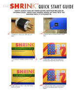
AirFlowPatternforBlodgettConveyorOvens
Heated Air
Combustion
Chamber
Return Air
Nozzle
Air Plate
Conveyor
Figure 1
SPECIFICATIONS
MT3240G MT3240E
Belt Width 32” (81 cm) 32” (81 cm)
Cooking Zone Length 40” (102 cm) 40” (102 cm)
Baking Area 8.89 Sq. Ft. (0.83 m
2
) 8.89 Sq. Ft. (0.83 m
2
)
Dimensions
(single unit)
72” x 56” x 20”
(183 cm x 142 cm x 51 cm)
72” x 56” x 20”
(183 cm x 142 cm x 51 cm)
Maximum Input 100,000 BTU/Hr. (24 kW/Hr.) 24 kW/Hr.
Maximum Operating
Temperature
600_F (315_C) 600_F (315_C)
Product Clearance 3.5” (6. 4 cm) 3.5” (6. 4 cm)
Power Supply U.S. and Canadian
120/208-240VAC, 1Φ,60Hz,
5amp,3wire
General Export
220-240VAC, 1Φ, 50Hz, 4 amp
3wire
U.S. and Canadian
208VAC, 3Φ, 60Hz, 67 amp, 3 wire
240VAC, 3Φ, 60Hz, 58 amp, 3 wire
General Export
220/380, 3Φ, 50Hz, 37 amp, 3 wire
240/415VAC, 3Φ, 50Hz, 34 amp, 3 wire
Gas Supply Natural Gas:
4.5” W.C. (1.1 kPa) minimum
10.5” W.C. (2.61 kPa) maximum
Propa ne:
11.0” W.C. (2.74 kPa) minimum
13.0” W.C. (3.2 kPa) maximum
None
GasSupplyConnection 3/4” NPT None

Introduction
3
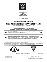
Oven Components
Conveyor Belt --- stainless steel chain link (con-
veyor) belt that carries product through the oven.
ConveyorBeltMasterLinks --- allow easy remov-
al of the conveyor belt for maintenance and clean-
ing. Identifiedby locating doublespacesbetween
regular links on belt.
Conveyor Belt Support Assembly (drive & idle
sides) ---locatedonbothendsofovendeck.Drive
side support drives conveyor belt.
Conveyor Belt Tensioners --- maintain tensionon
theendoftheconveyorbelt.
Control Box --- contains electrical wiring, cooling
fan, drive motor and drive chain.
Drive Motor --- provides power to move the con-
veyor belt.
Drive Chain --- connects the drive motorsprocket
to the drive side conveyor belt support sprocket.
Baking Chamber --- products pass through the
bakingchamber on the conveyorbelt forcooking.
Nozzles --- distribute heated air to the bottom of
the baking chamber. Located insidethe oven,un-
der the conveyor belt.
NozzleHold-DownBracket --- holdsthefrontend
ofthenozzles inposition. Located insidetheoven.
Return Air Diverters --- diverts return air from the
baking chamber back to the combustion cham-
ber. Ensures even baking throughout oven. Lo-
cated inside the oven, beneath the nozzles.
Upper End Plug --- keeps heat in the bak ing
chamber.Locatedoneachendabovetheconvey-
or belt.
Lower End Plug --- helps keep heat in the baking
chamber. Located at each end below the convey-
or belt.
Crumb Pan --- catches crumbs from products on
theconveyor.Locatedunderconveyorbeltatboth
ends of the baking chamber.
Air Flow Plate --- distributes heated air to top of
bakingchamber. Locatedinsideofovenat thetop
of baking chamber.
Emergency Shut Down Switch --- allows user to
turn oven and conveyor off in an emergency. Do
not use f or general shut down.
Lower
End Plug
Upper
End Plug
Crumb
Pan
Remote
Computer
Control
Integral
Computer
Control
Product Stop
Crumb
Pan
Conveyor
Belt
Belt
Tensioner
Air Flow
Plate
Nozzles
Air Diverters
Handle
Conveyor
Support
Conveyor
Support
Figure 2

Installation
4
Delivery and Insp ection
All Blodgett ovens are shipped in containers to
preventdamage. Upondelivery ofyour newoven:
D
Inspecttheshippingcontainerforexternaldam-
age. Any evidence of damage should be noted
onthe delivery receiptwhich mustbe signedby
the driver.
D
Uncrate the oven and check for internal dam-
age. Carriers will accept claims for concealed
damage if notifiedwithin fifteen days ofdelivery
and the shipping container is retained for in-
spection.
The Blodgett Oven Company cannot assume
responsibility for loss or damage suffered in
transit. The carrier assumed full responsibility
for delivery in good o rder when the shipment
was accepted. We are, however, prepared to
assist you if filing a cl aim is necessary.
The oven can now be moved to the installation
site.Checkthe followinglist withFigure 2 onpage
3 to be sure all items w ere received.
Part Description
Qty.
Main oven body 1
Left conveyor support assembly 1
Right conveyor support assembly 1
Belt tensioners 2
Rolledwireconveyorbelt 1
Crumb pans 2
Air flow plate 1**
Nozzles 6**
Packet containing:1/ 2-13alignment
pins
1*
Air diverters 3**
Upper end plugs 2**
Lower end plugs 2**
Product stop 1
Part Description Qty.
Packet containing: 12 3/8 x 16 hex
head bolts
1*
Packet containing: Conveyor belt
innerandoutermasterlinks
1*
Extra piece of wire conveyor belt 1*
Owner’s manual 1*
Optional remote cooking computer 1
Optional computer cables 1
Packetcontaining:optionalcomput-
er cable clamps
1
NOTE: * Item not shown.
** Shipped installed

Installation
5
Oven Location and Ventilation
LOCATION
The well planned and proper placement of your
oven will result in long term operator convenience
and satisfactory performance.
The following clearances must be maintained be -
tween the ovenand any combustible ornon -com-
bustible construction.
MT3240G
D
Oven body sides --- 18” (46 cm)
D
Oven body back --- 2” (5 cm)
MT3240E
D
Oven body sides --- 20” (51 cm)
D
Oven body back --- 2” (5 cm)
Thefollowingclearancesmustbeavailableforser-
vicing.
All units
D
Oven body sides --- 38” (97 cm)
D
Oven body back --- 28” (71 cm)
NOTE: Ongasmodels,routineservicingcanusu-
ally be accomplished within the limited
movement provided by the gas hose re-
straint. If the oven needs to be moved fur-
ther from the wall, the gas must first be
turned offanddisconnectedfromtheoven
before removing the restraint. Reconnect
the restraint after the oven has been re-
turned to its regular position.
It is essential that an adequate air supply to the
oven be maintained to provide a sufficient flow of
combustion and ventilation air.
D
Place the oven in an area that is free of drafts.
D
Keeptheovenareafreeand clearofallcombus-
tiblessuchaspaper,cardboard,andflammable
liquids and solvents.
D
Do not place the ovenon a curb base or seal to
awall.Thiswillrestricttheflow ofairandprevent
proper ventilation to the blower motors. This
condition must be corrected to prevent perma -
nent damage to the oven.
VENTILATION
Ongasmodelsthenecessityforaproperlyde-
signed and installed ventilation system cannot be
over emphasized. This system allows the oven to
function properly while removing unwanted va-
porsand productsof combustionfrom theoperat -
ing area.
This oven must be vented with a properly de-
signed mechanically driven exhaust hood. The
hood should be sized to completely cover the
equipment plus an overhang of at least 6” (15cm)
on all sides not adjacent to a wall. The distance
from thefloortotheloweredge ofthe hoodshould
not exceed 7’ (2.1m). The capacity of the hood
should be sized appropriately and provisions
should be made for adequate makeup air.
U.S. and Canadian installations
Refer to your local ventilation codes. In the ab-
sence of local codes, refer to the National ventila-
tion code titled, “Standard for the Installation of
Equipment for the Removal of Smoke and Grease
Laden Vapors from Commercial Cooking Equip-
ment”, NFPA-96-Latest Edition.
General export installations
Installation must conform with Local and National
installation standards. Local installation codes
and/or requirements may vary. If you have any
questionsregardingtheproper installationand/or
operation of your Blodgett oven, please contact
yourlocaldistributor.Ifyoudonothavealocaldis-
tributor,pleasecalltheBlodgettOvenCompanyat
0011-802-860-3700.
WARNING:
Failure to properly vent the oven can be
hazardous to the health of the operator
and may result in operational problems,
unsatisfactory baking and possible dam-
age to the equipment.
Damagesustainedasa directresultofim-
proper ventilation will not be covered by
the Manufacturer’s warranty.

Installation
6
Oven Assembly
OVEN SUPPORTS AND CASTERS
1. Bolt the supports to the oven with 3/8-16 hex
head bolts.
NOTE: Install the locking casters on the front
of the oven.
2. Carefully place the oven onto casters. Have
several persons lift the oven off the pallet and
set it onto the casters.
3. Engage the brakes on the front casters.
Figure 3
STACKING THE OVENS
1. Install the legs on the bottom unit.
2. Rest the top oven on its back.
3. Install the four oven alignment pins into the
holes provided on the bottom of the oven.
NOTE: See Figure 4 for location of alignment
pins.
4. Carefully lift the upper oven off the pallet and
place it on the lower oven. Have several per-
sonslifttheovenoffthepalletandsetitonto
the casters.
5. Locate alignment pins with holes in frame of
the bottom oven.
Alignment Pin
Bottom oven
Figure 4
6. Install the stacking rails between the control
boxes.Onerailwillbeonthefrontofthecon-
trol box and the other at the back of the box.
Securew ithscrew satthet opofthelowerbox.
Front
Stacking
Rail
Rear
Stacking
Rail
Figure 5

Installation
7
Oven Assembly
CONVEYOR BELT SUPPORT
1. Slide the left conveyor support (with sprocket
ontheendoftheshaft)intothesupporttracks.
The sprocket must be inside the control box
after being pushed into the oven.
Figure 6
2. Install the drive chain around the drive motor
and the sprocket on the conveyor support.
Push the support back to tighten the chain.
Figure 7
3. Tighten the four bolts on the control box.
4. Slide the right conveyor support into the sup-
port tracks until it touches the left stop.

Installation
8
Oven Assembly
CONVEYOR BELT
Besuretoinstallthebeltfromlefttoright.Thecon -
veyorbelthasloopsonbothsides.Theloopsmust
travel back wards on the conveyor support. See
Figure 8.
Belt Top
Direction of
Conveyor Travel
Figure 8
Unlessspecifiedotherwise, conveyor travelis fac-
tory set for left to right operation when facing the
front of the oven. To change direction:
D
Reverse the polarity of the drive motor. Inter-
change the black and w hite motor leads at the
D .C. controller located in the control panel.
D
Installthe conveyor belt from the left side of the
oven.
To thread the conveyor belt
1. Startfromt he righth andsideofthe oven,low-
erlevelfirst.Unrollthebeltasshownin
Figure 9, otherwise the belt will be upside
down. Leave about one foot hanging out on
the left side
NOTE: If belt travel is from left to right, start
fromtheleftsideoftheoven.
2. Take the remainder of the belt, loop it around
the rightshaft. Pushthrough onthe upperlev-
el.
3. The two ends of the belt should be approxi-
mately6 -9inches past the leftshaftontheup-
per levelof the beltsupport.Rightshaft if right
to left travel is required.
Figure 9
Figure 10

Installation
9
Oven Assembly
4. Install inner master links. See Figure 11 and
Figure 12.
Upside-down
Proper
Position
Figure 11
Figure 12
5. Install the outer master links. See Figure 13
and Figure 14
NOTE: Theextra pieceofwirebeltcanbe usedto
makeadditional master links if theoriginal
links are lost or damaged.
Figure 13
Figure 14

Installation
10
Oven Assembly
CONVEYOR BELT TENSIONER
NOTE: Each tensioner installs between the idle
endoftheconveyor (theside oppositethe
drive) and the lower end plug.
1. Compress the tensioner assembly spring by
hand.
2. Engage the tensioner pin with the hole in the
low er end plug.
3. Lifttoengagethepinontheoppositesidewith
the conveyor.
Figure 15
CRUMB PANS
1. Installcrumbpansundereachendofthe con-
veyor.
Figure 16
OPTIONAL REMOTE COMPUTER CONTROL
1. Drill the mounting holes for the cooking com-
puter support base.
2. Mount the support base and cable support
bracket to the wall.
3. Stackthecookingcomputer(s)on thesupport
base. Connect the cables at the rear of the
controller.
4. Secure the cables to t he cable clampsupport
bracketandtotherearof theovenusingcable
clamps and screws.
NOTE: DO NOT ov ertighten the cable
clamps. Damage to the wires mayoc-
cure causing the computer to fail.
Cable Clamp
Support Bracket
Cooking Computer
Support Base
Cooking Computer
Figure 17

Installation
11
Utility Connections --- Standards and Codes
THE INSTALLATION INSTRUCTIONS CON-
TAINED HEREIN ARE FOR THE USE OF QUALI-
FIEDINSTALLATIONANDSERVICEPERSONNEL
ONLY. INSTALLATION OR SERVICE BY OTHER
THAN QUALIFIED PERSONNEL MAY RESULT IN
DAMAGE TO THE OVEN AND/OR INJURY TO
THE OPERATOR.
Qualified installation personnel are individuals, a
firm, a corporation, or a company which either in
person or through a representative are engaged
in, and responsible for:
D
the installation or replacement of gas piping
and the connection, installation, repair or serv-
icing of equipment.
D
the installationofelectricalwiringfrom the elec-
tric meter, main control box or service outlet to
the electric appliance.
Qualified installation personnel must be experi-
enced in such work, familiar with all precautions
required,andhavecompliedwithallrequirements
of state or local authorities having jurisdiction.
U.S. and Canadian installations
Installation must conform with local codes, or in
the absence of local codes, with the National Fuel
Gas Code, NFPA54/ANSI Z223.1---Latest Edition,
the Natural Gas Installation Code CAN/CGA-
B149.1 or the Propane Installation Code, CAN/
CGA-B149.2 as applicable.
All ovens, when installed, must be electrically
groundedinaccordancewithlocalcodes,orinthe
absenceoflocalcodes,withtheNationalElectrical
Code, ANSI/NFPA 70---Latest Edition and/or Cana-
dian National Electric Code C22.2 as applicable.
General export installations
Installation must conform with Local and National
installation standards. Local installation codes
and/or requirements may vary. If you have any
questionsregardingtheproper installationand/or
operation of your Blodgett oven, please contact
yourlocaldistributor.Ifyoudonothavealocaldis-
tributor,pleasecalltheBlodgettOvenCompanyat
0011-802-860-3700.

Installation
12
Gas Connection
GAS PIPING
Aproperlysizedgassupplysystemisessentialfor
maximum oven performance. Piping should be
sized to provide a supply of gas sufficient t o meet
themaximumdemandofallappliancesontheline
without loss of pressure at the equipment.
Example:
NOTE: BTU values in the following example are
for natural gas.
You purchase a MT3240G conveyor oven to add
to your existing cook line.
1. AddtheBTUratingofyourcurrentappliances.
Pitco Fryer 120,000 BTU
6 Burner Range 60,000 BTU
Deck Oven 50,000 BTU
Total 230,000 BTU
2. Add the BTU rating of the new oven to the to -
tal.
Previous Total 230,000 BT U
MT3240G 100,000 BTU
New Total 330,000 BTU
3. Measure the distance from the gas meter to
the cook line. Thisis the pipe length.Let’ssay
thepipelengthis30’(9.14m)andthepipe
size is 1” (2.54 cm).
4. Uset he appropriatet able todetermine the to-
tal capacity of your current gas piping.
The total capacity for this example is 375,000
BTU. Since the total required gas pressure,
330,000 B TU is less than 375,000 BTU, t he
current gas piping will not have to be in-
creased.
NOTE: TheBTUcapacitiesgiveninthe tables are
for straight pipe lengths only. Any elbows
orotherfittings willdecreasepipecapaci-
ties. Contact your local gas supplier if you
have any questions.
Maximum Capacity of Iron Pipe in Cubic F eet
of Natural Gas Per Hour
(Pressure drop of 0.5 Inch W.C. )
Pipe
L
e
n
g
t
h
Nominal Size, Inches
L
eng
t
h
(ft)
3/4” 1” 1-1/4” 1-1/2” 2”
10 360 680 1400 2100 3950
20 250 465 950 1460 2750
30 200 375 770 1180 2200
40 170 320 660 990 1900
50 151 285 580 900 1680
60 138 260 530 810 1520
70 125 240 490 750 1400
80 118 220 460 690 1300
90 110 205 430 650 1220
100 103 195 400 620 1150
From the National Fuel Gas Code Part 10 Table 10-2
Maximum Capacity of Pipe in Thousands of
BTU/hr of Undiluted P.P. Gas at 11” W.C.
(Pressure drop of 0.5 Inch W.C. )
Pipe Length
(
f
t
)
Outside Diameter, Inches
p
g
(ft)
3/4” 1” 1-1/2”
10 608 1146 3525
20 418 788 2423
30 336 632 1946
40 287 541 1665
50 255 480 1476
60 231 435 1337
70 215 404 1241
80 198 372 1144
90 187 351 1079
100 175 330 1014
From the National Fuel Gas Code Part 10 Table 10-15

Installation
13
Gas Connection
PRESSURE REGULATION AND TESTING
MT3240G ovens are rated at 100,000 BTU/Hr. (24
kW/Hr.)Eachovenhasbeenadjustedat thefacto-
ry to operate with the type of gas specified on the
rating plate attached to the left side of the control
panel.
Each oven is supplied with a regulator to maintain
thepropergaspressure.The regulator isessen-
tial to the proper operation of the oven and
shouldnotberemoved.Itispresettoprovidethe
oven with 3.5”W.C. (0.87 kPa) for natural gas and
10.0” W. C. (2.50 kPa) for Propane while t h e flame
is on. The regulator is located on top of the gas
valve, between the manual shutoff and solenoid
valves.
DO NOT INSTALL AN ADDITIONAL REGULATOR
WHERE THE OVEN CONNECTS TO THE GAS
SUPPLY UNLESS THE SUPPLY EXCEEDS THE
MAXIMUM.
NOTE: The maximum gas supply pressure to the
oven is 10.5” W.C. (2.61 kPa) for natural
gas and 13” W.C. (3.2 kPa) for Propane
gas.Theminimumgassupply pressureto
the oven is 4.5” W.C. (1.1 kPa) for natural
gasand 11.0”W.C. (2.74 kPa) forPropane
gas.
Installation must conform with local codes, or in
the absence of local codes, with the National Fuel
Gas Code, NFPA54/ANSI Z223.1---Latest Edition,
the Natural Gas Installation Code CAN/CGA-
B149.1 or the Propane Installation Code, CAN/
CGA-B149.2 as applicable.
The oven and its individual shutoff valve must be
disconnected from the gas supply piping system
during any pressure testing of that system at test
pressuresinexcessof1/2psig(3.45kPa).
The oven must be isolated from the gas supply
piping system by closing its individual manual
shutoff valve during any pressure t esting of the
gas piping system at test pressures equal or less
than 1/2 psig (3.45kPa).

Installation
14
Gas Connection
GAS HOSE RESTRAINT
If the oven is mounted on casters, a commercial
flexible connector with aminimum of 3/4” (1.9 cm)
inside diameter must be used along with a quick
connect device.
The restraint, supplied with the oven, must be
used to limit the movement of the unit so that no
strain is placed upon the flexible connector. The
restraint should be fastened to the base frame of
the ovenas closetotheflexibleconnector as pos-
sible. It should be short enough to prevent any
strain on the connector. W ith the restraint fully
stretched the connector should be easy to install
and quick connect.
Therestraint(ie:heavygaugecable)shouldbeat-
tached without damaging the building. D O NOT
use the gas piping or electrical conduit for the at-
tachment of the permanent end of the restraint!
Use anchorboltsinconcrete orcement block. On
wooden walls, drive hi test wood lag screws into
the studs of the wall.
WARNING!!
If the restraint is disconnected for any
reaso n it must be reconnected when the
oven is returned to its original position.
U.S. and Canadian installations
The connector must comply with the Standard for
Connectors for Movable Gas Appliances, ANSI
Z21.69 or Connectors For Moveable Gas Ap-
pliances CAN/CGA -6.16 and a quick disconnect
device that complies with the Standard for Quick-
Disconnect Devices for Use With Gas Fuel, ANSI
Z21.41or Quick DisconnectForUseWithGasFuel
CAN 1-6.9. Adequate means must be provided to
limit the movement of the appliance without de-
pending on the connection and the quick discon-
nect device or its associated piping.
A drip leg must be used at each appliance. Refer
to NFPA54/ANSI Z223.1 - Latest Edition (National
Fuel Gas Code) for proper drip leg installation.
General export installations
The restraint and quick connect must conform
withLocaland Nationalinstallation standards. Lo-
cal installation codes and/or requirements may
vary.Ifyouhaveanyquestionsregardingtheprop-
er installation and/or operation of your Blodgett
oven, please contact your local distributor. If you
do not have a local distributor, please call the
Blodgett Oven Company at 0011-802-860-3700.
Tighten after
adjustment
(See VIEW A)
VIEW A
Gas
Hose
Socket
Quick Connect
Socket
Plug
IMPORTANT:
Cable restraintshouldbe fastenedascloseaspos-
sible to flexible connector and short enough to pre-
vent any strain on flexible connect. At maximum
stretchofshortenedrestraintthe flexibleconnector
should be easy to install and quick connect.
Installation of Gas Hose and Restraint
Gas Supply Line
BackPanel
Attachment Plate.
(Secure with spacer bracket mounting bolt)
Flexible Restraint Installation
Figure 18

Installation
15
Electrical Connection
Before making any electrical connections to this
unit, check that the power supply is adequate for
the voltage, amperage, and phase requirements
stated on the rating plate.
Wiring diagrams accompanies this manual and
are attached inside the control box.
MT3240G
U.S. and Canadian installations
The MT3240G requires a 15 Amp, 60HZ, 1Φ,
208-240VAC, 4 wire service consisting of L1, L2,
neutraland ground.Wiringfromthe powersource
totheseunitsmustbeaminimumof#16AWGCU.
stranded wire or larger.
Single phase units MUST NOT be connected to
the highleg ofa three phase system. The highleg
refers to a potential of 240 volts betw een one
phase and neutral. The remaining two legs have
a potential of 120 volts between each phase and
neutral.
General export installations
The MT3240G requires a 15 Amp, 50Hz, 1Φ,
220-240VAC, 3 wire service consistingof L1,neu-
tral and ground. Use 90_Cwireandsizewireac-
cording to local codes.
WARNING!!
Incorrect single phase wiring may result
in extensive damage to electrical compo-
nents and fire in the control panel.
MT3240E
U.S. and Canadian installations
The MT3240E requires a 80 amp, 60 HZ, 3Φ,
208-240 VAC 4 wire service consisting of L1, L2,
L3,andground.Use 90_CwireandsizetoNation-
al Electric or local codes.
General export installations
The MT3240E requires a 56 amp, 50 HZ, 3Φ,
220-240 VAC, 4 wire service consisting of L1, L2,
L3andground.Use90_CwireandsizetoNational
Electric or local codes.
THE BLODGETT OVEN COMPANY CANNOT AS-
SUMERESPONSIBILITYFORLOSSORDAMAGE
SUFFEREDASARESULTOFIMPROPERINSTAL-
LA TION.
MT3240G
MT3240E
L1
N
120
OvenSupply
L2
120
208-240
U.S. and Canadian Installations
L1
L2
OvenSupply
L3
208-240
U.S. and Canadian Installations
L1
N
220-240
OvenSupply
General Export Installations General Export Installations
415/
380
L1
L2
L3
OvenSupply
N
415/380
415/380
240/
220
Figure 19

Operation
16
Safety Information
THE INFORMATION CONTAINED IN THIS SEC-
TIONISPROV IDEDFORTHEUSEOFQUALIFIED
OPERATING PERSONNEL. QUALIFIED OPERAT-
ING PERSONNEL ARE THOSE WHO HAVE
CAREFULLY READ THE INFORMATION CON-
TAINED IN THIS MANUAL, ARE FAMILIAR WITH
THE FUNCTIONS OF THE OVEN AND/OR HAVE
HAD PREVIOUS EXPERIENCE WITH THE OP-
ERATIONOFTHEEQUIPMENT DESCRIBED.AD-
HERENCE TO THE PROCEDURES RECOM-
MENDED HEREIN WILL ASSURE THE
ACHIEVEMENT OF OPTIMUM PERFORMANCE
AND LONG, TROUBLE-FREE SERVICE.
Please take the time to read the following safety
andoperatinginstructions.Theyarethe keytothe
successful operation of your Blodgett conveyor
oven.
SAFETY TIPS
Fo r your saf ety read befo re operating
What to do if you smell gas:
D
DO NOT try to light any appliance.
D
DO NOT touch any electrical switches.
D
Use an exterior phone to call your gas supplier
immediately.
D
If you cannot reach your gas supplier, call the
fire department.
What to do in the event of a power failure:
D
Turn all switches to off.
D
DO NOT attempt to operate the oven until the
power is restored.
NOTE: In the event of a shut-down of any kind, al-
low a five (5) minute shut off period before
attempting to restart the oven.
What to do for emergency shut do wn:
D
For ovens with remote control, the unit is
equippedwithanemergencyshutdownswitch.
Should you need to stop the belt, fans, or heat
press the emergency switch. DO NOT use the
emergency switch as a general on/off switch.
General safety tips:
D
DO NOT use tools to turn off the gas control. If
thegascannotbeturnedoffmanuallydonott ry
to repair it. Call a qualified service technician.
D
If the oven needs to be moved for any reason,
the gas must be turned off and disconnected
from the unit before removing the restraint
cable. Reconnect the restraint after the oven
has been returned to its original location.
D
DO NOT remove the control box cover unless
the oven is unplugged.

Operation
17
Cooking Computer
CONTROL DESCRIPTION
1. DIGITAL DISPLAY --- displays the time, tem-
perature and controller related information.
2. OVEN ON/OFF --- controls power to the oven.
3. NUMERIC KEYS --- used to enter numbers in
the programming mode.
4. CLEAR KEY --- clears the display if an error is
made in the programming mode.
5. SET TEMP KEY --- press to view or program
the temperature setpoint.
6. ACT TEMP KEY --- press to view the current
oven temperature.
7. TIME KEY --- press to view or program the
cook time.
8. PROG/ENTER KEY --- press to enter and exit
the programming mode and lock in pro-
grammed settings.
9. STATUS LAMPS --- when lit indicate the fan or
burners are operating.
PROGRAMMING
Programming the Cook Time:
1. Press the PROGRAM/ENTER key (8).
2. Presst he TIME key(7). The displayreadsSET
D
TIME-?.
3. Use the NUMERIC keys (3) to enter the de-
sired cook time. If an error is made, press t he
CLEAR key (4) and re-enter the number.
4. Press the PROGRAM/ENTER key (8) to store
the new cooktime in the computer’s memory.
Programming the Temperature:
1. Press the PROGRAM/ENTER key (8).
2. Press the SE T TEM P key (5). The display
reads SET
D
TEMP-?.
3. Use the NUMERIC keys (3) to enter the de-
sired temperature set point. If an error is
made, press the CLEAR key (4) and re -enter
the number.
4. Press the PROGRAM/ENTER key (8) to store
the new temperature setpoint in the comput-
er’s memory.
1
2
3
45678
9
Figure 20

Operation
18
Cooking Computer
OPERATION
To turn the oven on:
1. TurnthemanualgasvalvetoON.(Gasmodels
only)
2. Press and hold the ON/OFF key (2). The dis-
play reads OFF when the oven is idle.
3. The STATUS LAMPS (9) light. The fans begin
to run. The heat rises to the temperature set-
ting stored in the computer’s memory. The
conveyor belt begins to travel at the speed
stored in memory.
4. The display flashes WAIT
D
LOW
D
SET
D
TIME
D
mmss until the oven reaches the pro -
grammed bake temperature.
5. The display reads READY and the HEAT lamp
(9)goes out. The ovenis now ready to accept
product.
To view the cook time setting:
1. Press the TIME key (7). The LED on the key
lights and the display flashes SET
D
TIME
D
mmss.
To display the actual oven temperature:
1. Press the ACT TEMP key (6). The LED on the
key lights and the display flashes ACTUAL
D
nnn_F.
To view the temperature set point:
1. Press the SET TEMP key (5). The LED on the
key lights and the display flashes SET
D
TEMP
D
nnn_F.
To turn the oven off:
1. Press the ON/OFF key (2). The oven is
equipped with a cool-down feature for motor
shaft andbearing protection. Thisenables the
blow er motor(s) to run regardless of the con-
troller status. The blower(s) continue to run
until the oven cools t o a safe temperature.
DISPLAY INFORMATION
WAIT
D
LOW --- the present oven temperature is
low er than t he set point temperature. When the
oven reaches the set point temperature the dis-
play changes to READY.
READY --- the oven is ready to accept product.
SET
D
TIME
D
mmss --- the current cook time set-
ting.
HIGH
D
TEMP --- the temperature is above the set
point. Wait until the display reads ready before
loading product.
HIGH
D
TEMP
D
LIMIT ---the oven t emperature ex-
ceeds the high limit. The Over Temperature Alarm
buzzer sounds. Shut the oven off and wait for the
unit to cool down.
HIGH
D
TEMP
D
PANEL --- thecontrolarea reaches
an excessive temperature. Shut the oven off and
wait for the unit to cool down.
PROBE
D
OPEN
D
PROBE
D
SHORT --- the tempera-
ture sensor has failed. The Alarm buzzer sounds.
Shut the oven off and contact a service represen-
tative.
/