Page is loading ...

Page 1 of 16
Installation and Operation Instructions
MATRIX-ENABLED
21/27/COVERT SERIES LIGHTBARS
IMPORTANT! Read all instructions before installing and using. Installer: This manual must be delivered to the end user.
WARNING!
Failure to install or use this product according to manufacturer’s recommendations may result in property damage, serious bodily/
personal injury, and/or death to you and those you are seeking to protect!
Do not install and/or operate this safety product unless you have read and understand the safety
information contained in this manual.
1. Proper installation combined with operator training in the use, care and maintenance of emergency warning devices are essential to
ensure the safety of emergency personnel and the public.
2. Emergency warning devices often require high electrical voltages and/or currents. Exercise caution when working with live electrical
connections.
3. This product must be properly grounded. Inadequate grounding and/or shorting of electrical connections can cause high current
arcing, which can cause personal injury and/or severe vehicle damage, including re.
4. Proper placement and installation is vital to the performance of this warning device. Install this product so that output performance of
the system is maximized and the controls are placed within convenient reach of the operator so that s/he can operate the system
without losing eye contact with the roadway.
5. It is the responsibility of the vehicle operator to ensure daily that all features of this product work correctly. In use, the vehicle operator
should ensure the projection of the warning signal is not blocked by vehicle components (i.e., open trunks or compartment doors),
people, vehicles or other obstructions.
6. The use of this or any other warning device does not ensure all drivers can or will observe or react to an emergency warning signal.
Never take the right-of-way for granted. It is your responsibility to be sure you can proceed safely before entering an intersection, drive
against trac, respond at a high rate of speed, or walk on or around trac lanes.
7. This equipment is intended for use by authorized personnel only. The user is responsible for understanding and obeying all laws
regarding emergency warning devices. Therefore, the user should check all applicable city, state, and federal laws and regulations.
The manufacturer assumes no liability for any loss resulting from the use of this warning device.
8. This product may contain high intensity LEDs staring directly into these lights could result in temporary and/or permanent vision
impairment.
Cross Section: Covert Series 1.6” x 12.3”
21 Series 2.1” x 12.3”
27 Series 2.7” x 12.3”
Max Input Voltage: 10-16 VDC
Nominal Input Voltage: 12 VDC
Fusing Requirement: 30A / 60A
Matrix Connectivity: Covert Series CAT5
21 / 27 Series CAT5
Temp. Range: -40ºC to 65ºC
(-40ºF to 149ºF)
Specications:
Light Module Current (@ 12 VDC):
27 Series Prizm Single Color 5 LED AL, WL, RD 0.7 A
27 Series Prizm Single Color 8 LED Directional 1.3 A
27 Series Prizm Single Color 12 LED Directional 1.7 A
27 Series Prizm Dual Color 24 LED Directional 2.0 A
27 Series Prizm Tri Color 24 LED Directional 1.1 A
21 Series Torus Single Color 3 LED AL, WL, TD 0.4 A
21 Series Torus Single Color 3 LED Directional 0.6 A
21 Series Torus Single Color 4 LED Directional 0.8 A
Covert / 21 Series Torus Dual Color 6 LED AL, WL, TD 0.6 A
21 Series Torus Single Color 6 LED Directional 1.1 A
21 Series Torus Single Color 8 LED Directional 1.3 A
Covert / 21 Series Torus Tri Color 9 LED AL, WL, TD 0.6 A
Covert / 21 Series Torus Dual Color 12 LED Directional 1.2 A
Covert / 21 Series Torus Dual Color 16 LED Directional 1.3 A
Covert / 21 Series Torus Tri Color 18 LED Directional 1.2 A
Additional Matrix Resources
Product Information: www.code3esg.com/us/en/products/matrix
Training Videos: www.youtube.com/c/Code3Inc
Matrix Software: http://software.code3esg.global/updater/matrix/downloads/Matrix.exe

Page 2 of 16
Installation & Mounting:
Mounting
Before proceeding with installation, plan all wiring and cable routing. Select the mounting location for the product on a at, smooth surface
and center the unit across the width of the vehicle. The mounting location should be chosen such that the product is level and visibility to
approaching trac is optimized.
Caution:
When drilling into any vehicle surface, make sure that the area is free from any electrical wires, fuel lines, vehicle upholstery, vehicle
support members, etc. that could be damaged.
Unpacking and Pre-Installation:
Carefully remove the product and place it on a at surface. Examine the unit for transit damage and locate all parts. If damage is found or
parts are missing, contact the transit company or Code 3. Do not use damaged or broken parts.
Ensure the product voltage is compatible with the planned installation.

Page 3 of 16
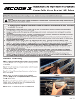
Direct Mount Option:
1. Remove the mounting feet from the lightbar.
2. Insert the four (4) 5/16”-18 carriage bolts in the channels on the under side of the lightbar.
3. Place the lightbar over the center of the vehicle and slide the mounting hardware into position near the curved edge when possible as
shown in FIGURE 2.
4. With the mounting hardware positioned, mark the location of the mounting hole centers on the roof of the vehicle. Remove the lightbar
and drill the mounting holes as marked.
5. Mount the lightbar as shown in FIGURE 1 and secure the unit. See the Wiring section of this manual for further wiring instructions.
CURVED ROOF EDGE
Figure 2
RUBBER STANDOFF
OVERSIZED FLAT WASHER
5/16” NYLON INSERT NUT
5/16”-18 CARRIAGE BOLT
VEHICLE ROOF
Figure 1

Page 4 of 16
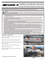
Pylon/Headache Rack Option:
1. Remove the mounting feet from the lightbar.
2. Insert the four (4) 5/16”-18 carriage bolts in the channels on the under side of the lightbar and loosely attach the mounting brackets.
3. Place the lightbar on the vehicle and slide the mounting brackets into position.
4. Secure the brackets to the lightbar with the supplied washers and nuts as shown in FIGURE 3.
5. With the mounting brackets positioned, mark the locations of the mounting hole centers on the roof of the vehicle. Remove the bar and
drill the mounting holes as marked.
6. Secure the mounting brackets to the vehicle with customer supplied hardware. See the Wiring section of this manual for further wiring
instructions.
BRACKET
5/16-18 CARRIAGE BOLT
RUBBER BUMPER
LIGHTBAR
5/16-18 NUT
1/2" BOLT AND MOUNTING
HARDWARE SUPPLIED BY
CUSTOMER
OVERSIZED FLAT WASHER
Figure 3

Page 5 of 16
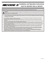
Strap Kit Option:
Important!
Mounting brackets are specic to the vehicle model. Please make sure the brackets are suitable for the vehicle before
installation.
1. Loosen the 5/16” nuts to allow the mounting feet to slide along the base of the lightbar. Loosely attach the mounting strap to each foot
using the supplied pan head phillips screws and lock washers.
2. Center the lightbar across the vehicle and align the strap mount brackets to hook into the gutter of the vehicles door frame as shown in
FIGURE 4.
3. Secure the feet to the lightbar in location by tightening the four (4) nuts on each foot.
4. Slowly tighten the pan head screws to secure the strap mount brackets to the lightbar feet and around the door gutters, keeping the
lightbar centered and level. Ensure the doors close completely and secure each strap mount bracket to the door frame. Mounting
geometry and parts will vary for dierent vehicles. See the Wiring section of this manual for further wiring instructions.
Figure 4
*For a full list of vehicle specic brackets, please reference a Code 3 catalog or contact a Code 3 representative.

Page 6 of 16
Wiring Instructions:
IMPORTANT! This unit is a safety device and it must be connected to its own separate, fused power point to assure its continued operation
should any other electrical accessory fail. Do not wire in parallel with any other accessory.
Notes:
• Larger wires and tight connections will provide longer service life for components. For high current wires it is highly recommended
that terminal blocks or soldered connections be used with shrink tubing to protect the connections. Do not use insulation displace-
ment connectors (e.g., 3M Scotchlock type connectors).
• Route wiring using grommets and sealant when passing through compartment walls. Minimize the number of splices to reduce volt-
age drop. High ambient temperatures (e.g., under-hood) will signicantly reduce the current carrying capacity of wires, fuses, and
circuit breakers. All wiring should conform to the minimum wire size and other recommendations of the manufacturer and be pro-
tected from moving parts and hot surfaces. Looms, grommets, cable ties, and similar installation hardware should be used to anchor
and protect all wiring.
• Fuses or circuit breakers should be located as close to the power takeo points as possible and properly sized to protect the wiring
and devices.
• Particular attention should be paid to the location and method of making electrical connections and splices to protect these points
from corrosion and loss of conductivity.
• Ground termination should only be made to substantial chassis components, preferably directly to the vehicle battery.
• Circuit breakers are very sensitive to high temperatures and will “false trip” when mounted in hot environments or operated close to
their capacity.
Caution:
Disconnect the battery before wiring up the lightbar, to prevent accidental shorting, arcing and/or electrical shock.
Connect the red (power) and black (ground) wires from the serial lightbar to a nominal 12 VDC supply, along with a customer supplied in-line,
slow blow ATC style fuse. Check the box label or wire tag to determine if your lightbar requires a 30A or 60A fuse. This depends on the
number and type of light modules installed inside. Nothing less than a 30A fuse is permitted. Please note that the fuse holder selected by
the customer must also be rated by its manufacturer to meet or exceed the corresponding fuse ampacity. See Figure 5 for details.
All Matrix compatible lightbars should also connect back to a central node, such as the Serial Interface Box or Z3 Serial Siren, to establish
serial communication with the larger network. Depending on the lightbar model, this cable will involve either a CAT5 connection or bare wire,
twisted pair termination labeled B Y at the central node. Connect the serial lightbar to your central node, according to the Matrix connectivity
specied for the particular model at the beginning of this document. Please note, for CAT5 connections the PRI-1 port must always be
utilized rst, before additional devices can be connected to the SEC-2 port. See Figure 5 for details.
Figure 5

Page 7 of 16
The Matrix network is designed to conveniently accommodate a large number of accessory devices. As more products utilizing CAT5
connectivity are integrated into the vehicle, routing of the cables can be accomplished in ‘daisy chain’ fashion, if desired. Serial lightbars
utilizing CAT5 will always be the last device in either the PRI-1 or SEC-2 chain. Further instructions, features, and control options are
detailed in the installation manual of the customer selected central node.
The following table indicates the default ash patterns of the serial lightbar. These patterns are activated by other Matrix compatible
products, connected to the lightbar. These can easily be recongured as desired, in the Matrix Congurator. See Matrix Conguration Quick
Start Manual for details.
Flash Patterns
Default Description
Arrowstik Right Building Fast
Right Scene Steady
Left Scene Steady
Takedown/Alley Flash Single Flash 150 - Alternating
Arrowstik Left Building Fast
Dim 30%
Cruise Dim, Full Bar
Level 3 Pursuit - Alternating
Level 2 Triple Flash 115
Level 1 Sweep
Takedown Steady
Front Cut
Arrowstik Flash Quad Flash 115

Page 8 of 16
21 & 27 Series Lightbar Flash Pattern Chart
No. Description FPM
SAE J845 (180°)* SAE J595 CA TITLE 13
A, B, R W A, B, R W A, B, R
1 Sweep - - - - - -
2 Dual End Rotate - - - - - -
3 Pursuit - - - - - -
4 Pursuit (Steady Front Primary) - - - - - -
5 Cruise Low - - - - - -
6 Cruise Low Full Bar - - - - - -
7 Cruise High - - - - - -
8 Flicker Cruise Low - - - - - -
9 Flicker Cruise High - - - - - -
10 Takedown/Alley Flash - - - - - -
11 Single Flash 75 Class 1S Class 1S Class 1 Class 1 Class B
12 Triple Flash 115 Class 2S Class 2S Class 2 Class 2 -
13 Triple Flash (Steady Front Primary) 115 Class 2S Class 2S Class 2 Class 2 -
14 Quad Flash 115 Class 1S Class 1S** Class 1 Class 1*** -
15 Single Flash 150 Class 2S Class 2S Class 2 Class 2 -
16 Single Flash 250 - - - - -
17 Single Flash 375 - - - - -
18 Double Flash 75 Class 1S Class 1S Class 1 Class 1 Class B
19 Double Flash 115 Class 1S Class 1S Class 1 Class 1 Class B
20 Double Flash 150 Class 1S Class 1S Class 1 Class 1 -
21 Triple Flash 60 Class 1S Class 1S Class 1 Class 1 Class B
22 Triple Flash 150 Class 1S Class 1S Class 1 Class 1 -
23 Quad Flash NFPA 75 Class 1S Class 1S Class 1 Class 1 Class B
24 Quad Flash 150 Class 1S Class 1S Class 1 Class 1 -
25 Five Flash 75 Class 1S Class 1S Class 1 Class 1 Class B
26 Five Flash 150 Class 1S Class 1S Class 1 Class 1 -
27 Six Flash 60 Class 1S Class 1S Class 1 Class 1 Class B
28 Six Flash 80 Class 2S Class 2S Class 2 Class 2 -
29 All Bar Rotate - - - - - -
30 Intersection - - - - - -
31 Variable Flash - - - - - -
32 Cycle Flash - - - - - -
33 360 Combo - - - - - -
34 Hyper Flash - - - - - -
* Applies to lightbars with a minimum of the indicated colors in two corners
** 21 and 27 series lightbars with single color modules in the corners are SAE Class 2S
*** 21 series lightbars with single color white modules are SAE J595 Class 2

Page 9 of 16
Covert Bar Flash Pattern Chart
No. Description FPM
SAE J845 (180°)* SAE J595 CA TITLE 13
A, B, R W G A, B, R W A, B, R
1 Sweep - - - - - - -
2 Dual End Rotate - - - - - - -
3 Pursuit - - - - - - -
4 Pursuit (Steady Front Primary) - - - - - - -
5 Cruise Low - - - - - - -
6 Cruise Low Full Bar - - - - - - -
7 Cruise High - - - - - - -
8 Flicker Cruise Low - - - - - - -
9 Flicker Cruise High - - - - - - -
10 Takedown/Alley Flash - - - - - - -
11 Single Flash 75 Class 1S Class 1S Class 3S Class 1 Class 1 Class B
12 Triple Flash 115 Class 2S Class 2S Class 3S Class 2 Class 2 -
13 Triple Flash (Steady Front Primary) 115 Class 2S Class 2S Class 3S Class 2 Class 2 -
14 Quad Flash 115 Class 1S Class 2S Class 3S Class 1 Class 2 -
15 Single Flash 150 Class 2S Class 2S Class 3S Class 2 Class 2 -
16 Single Flash 250 - - - - - -
17 Single Flash 375 - - - - - -
18 Double Flash 75 Class 1S Class 1S Class 3S Class 1 Class 1 Class B
19 Double Flash 115 Class 1S Class 1S Class 3S Class 1 Class 1 Class B
20 Double Flash 150 Class 1S Class 1S Class 3S Class 1 Class 1 -
21 Triple Flash 60 Class 1S Class 1S Class 3S Class 1 Class 1 Class B
22 Triple Flash 150 Class 1S Class 1S Class 3S Class 1 Class 1 -
23 Quad Flash NFPA 75 Class 1S Class 1S Class 3S Class 1 Class 1 Class B
24 Quad Flash 150 Class 1S Class 1S Class 3S Class 1 Class 1 -
25 Five Flash 75 Class 1S Class 1S Class 3S Class 1 Class 1 Class B
26 Five Flash 150 Class 1S Class 2S Class 3S Class 1 Class 1 -
27 Six Flash 60 Class 1S Class 1S Class 3S Class 1 Class 1 Class B
28 Six Flash 80 Class 2S Class 2S Class 3S Class 2 Class 2 -
29 All Bar Rotate - - - - - -
30 Intersection - - - - - -
31 Variable Flash - - - - - -
32 Cycle Flash - - - - - -
33 360 Combo - - - - - -
34 Hyper Flash - - - - - -
* Applies to lightbars with a minimum of the indicated colors in two corners

Page 10 of 16
Replacement Parts and Assemblies:
Figure 5 - Torus Takedown
Figure 13 - Power Hub
The Power Hub provides additional power,
on demand, to individual light modules
installed inside the lightbar. It is used only
when the cumulative draw of light modules
chosen exceeds a specied limit. Max
capacity is equal to the Lightbar Controller
capacity, i.e. an additional 15A RMS, and
up to 35A peak, over the entire operating
temperature range.
Figure 12 - Lightbar Controller
The Lightbar Controller transfers network
communication from other Matrix devices
to all the individual light modules installed
inside the lightbar. It also provides power, on
demand, to the light modules. Max capacity
is 15A RMS, and up to 35A peak, over the
entire operating temperature range.
Caution! Lightbar Controller outputs
should only be connected to Matrix
Compatible Light Modules. The warranty
will be void if unsupported products are
connected to the controller.
There are many dierent types of light-heads producing various warning signals in the lightbar as explained below. All 21/27 Series Lightbar
retaining screws need to be torqued to 40 +0/-5 IN-LBS (4.52 +0/- 0.56 Nm). Covert Series Lightbar retaining screws need to be torqued to
10 +/- 1 IN-LBS (1.13 +/- 0.11 N-M)
Note: LED modules are not user serviceable.
Figure 6 - Torus 3LED Directional
Figure 7 - Torus 4LED Directional
Figure 8 - Torus Directional/Corner Figure 9 - Prizm 5LED Takedown Figure 10 - Prizm 5LED Alley
Figure 11 - Prizm Directional/Corner

Page 11 of 16
Description Part No.
Modules
Serial Interface Box (SIB) CZMATSIB
Boards
Lightbar Master Controller Board CZMATLBC
Lightbar Power HUB Board CZMATPH
Lenses
21 Series, Lower Outboard Lens, Clear CZ2101C
21 Series, Lower Outboard Lens, Tint CZ2101T
21 Series, Lower Center 11" Lens, Clear CZ2111C
21 Series, Lower Center 11" Lens, Tint CZ2111T
21 Series, Lower Center 16" Lens, Clear CZ2116LC
21 Series, Lower Center 16" Lens, Tint CZ2116LT
21 Series, Upper Center 16" Lens, Amber CZ2116UA
21 Series, Upper Center 16" Lens, Blue CZ2116UB
21 Series, Upper Center 16" Lens, Black CZ2116BLK
21 Series, Upper Center 16" Lens, Clear CZ2116UC
21 Series, Upper Center 16" Lens, Red CZ2116UR
21 Series, Upper Center 16" Lens, Tint CZ2116UT
21/27 Series, Upper Center 11" Lens, Black CZ2127U11BLK
21/27 Series, Upper Center 11" Lens, Clear CZ2127U11C
21/27 Series, Upper Center 11" Lens, Red CZ2127U11R
21/27 Series, Upper Center 11" Lens, Blue CZ2127U11B
21/27 Series, Upper Center 11" Lens, Amber CZ2127U11A
21/27 Series, Upper 22.5" Lens, Amber CZ27U22A
21/27 Series, Upper 22.5" Lens, Blue CZ27U22B
21/27 Series, Upper 22.5" Lens, Black CZ27U22BLK
21/27 Series, Upper 22.5" Lens, Clear CZ27U22C
21/27 Series, Upper 22.5" Lens, Red CZ27U22R
21/27 Series, Upper 22.5" Lens, Tint CZ27U22T
21 Series, Upper Outboard Lens, Amber CZ21UA
21 Series, Upper Outboard Lens, Blue CZ21UB
21 Series, Upper Outboard Lens, Black CZ21UBLK
21 Series, Upper Outboard Lens, Clear CZ21UC
21 Series, Upper Outboard Lens, Red CZ21UR
21 Series, Upper Outboard Lens, Tint CZ21UT
21 Series, Upper Outboard Lens, Black, Photocell CZ21UBWI
21 Series, Lower 22.5" Lens, Clear CZ21L22C
21 Series, Lower 22.5" Lens, Tint CZ21L22T
27 Series, Lower Outboard Lens, Clear CZ2701C
27 Series, Lower Center 8" Lens, Clear CZ2708C
27 Series, Lower Center 11" Lens, Clear CZ2711C
27 Series, Upper Outboard Lens, Black CZ27UBLK
27 Series, Upper Outboard Lens, Red CZ27UR
27 Series, Upper Outboard Lens, Blue CZ27UB
27 Series, Upper Outboard Lens, Amber CZ27UA
27 Series, Upper Outboard Lens, Clear CZ27UC
27 Series, Lower 22.5" Lens, Clear CZ27L22C
27 Series, Upper Center 8" Lens, Clear CZ2708U

Page 12 of 16
Description Part No.
Lenses (continued)
27 Series, Upper Center 8" Lens, Blue CZ2708UB
27 Series, Upper Center 8" Lens, Amber CZ2708UA
27 Series, Upper Center 8" Lens, Black CZ2708UBLK
21/27 Series, Lower Center 18" Lens, Tint CR1618LSMK
21/27 Series, Lower Center 18" Lens, Clear CR1618LCLE
21/27 Series, Upper Center 18" Lens, Tint CR1618USMK
21/27 Series, Upper Center 18" Lens, Amber CR1618UAMB
21/27 Series, Upper Center 18" Lens, Clear CR1618UCLE
21/27 Series, Upper Center 18" Lens, Red CR1618URED
21/27 Series, Upper Center 18" Lens, Green CR1618UGRE
21/27 Series, Upper Center 18" Lens, Black CR1618UBLA
21/27 Series, Upper Center 18" Lens, Blue CR1618UBLU
21/27 Series, Upper Center 18" Lens, Tint CR1608LSMK
21/27 Series, Upper Center 18" Lens, Clear CR1608LCLE
21/27 Series, Upper Center 8" Lens, Tint CR1608USMK
Covert, Upper Center 8" Lens, Amber CR1608UAMB
Covert, Upper Center 8" Lens, Clear CR1608UCLE
Covert, Upper Center 8" Lens, Red CR1608URED
Covert, Upper Center 8" Lens, Green CR1608UGRE
Covert, Upper Center 8" Lens, Black CR1608UBLA
Covert, Upper Center 8" Lens, Blue CR1608UBLU
Covert, Lower Center 11" Lens, Tint CR1611LSMK
Covert, Lower Center 11" Lens, Clear CR1611LCLE
Covert, Upper Center 11" Lens, Tint CR1611USMK
Covert, Upper Center 11" Lens, Amber CR1611UAMB
Covert, Upper Center 11" Lens, Clear CR1611UCLE
Covert, Upper Center 11" Lens, Red CR1611URED
Covert, Upper Center 11" Lens, Green CR1611UGRE
Covert, Upper Center 11" Lens, Black CR1611UBLA
Covert, Upper Center 11" Lens, Blue CR1611UBLU
Covert, Lower Center 16" Lens, Tint CR1616LSMK
Covert, Lower Center 16" Lens, Clear CR1616LCLE
Covert, Upper Center 16" Lens, Tint CR1616USMK
Covert, Upper Center 16" Lens, Amber CR1616UAMB
Covert, Upper Center 16" Lens, Clear CR1616UCLE
Covert, Upper Center 16" Lens, Red CR1616URED
Covert, Upper Center 16" Lens, Green CR1616UGRE
Covert, Upper Center 16" Lens, Black CR1616UBLA
Covert, Upper Center 16" Lens, Blue CR1616UBLU
Covert, Lower 22.5" Lens, Tint CR1623LSMK
Covert, Lower 22.5" Lens, Clear CR1623LCLE
Covert, Upper 22.5" Lens, Tint CR1623USMK
Covert, Upper 22.5" Lens, Amber CR1623UAMB
Covert, Upper 22.5" Lens, Clear CR1623UCLE
Covert, Upper 22.5" Lens, Red CR1623URED
Covert, Upper 22.5" Lens, Green CR1623UGRE
Covert, 22.5”, green CR1623UGRE

Page 13 of 16
Description Part No.
Lenses (continued)
Covert, Upper 22.5" Lens, Black CR1623UBLA
Covert, Upper 22.5" Lens, Blue CR1623UBLU
Covert, Upper Center 18" Lens, Tint, Photocell CR1618PHOTOSMK
Covert, Upper Center 18" Lens, Amber, Photocell CR1618PHOTOAMB
Covert, Upper Center 18" Lens, Red, Photocell CR1618PHOTORED
Covert, Upper Center 18" Lens, Green, Photocell CR1618PHOTOGRE
Covert, Upper Center 18" Lens, Black, Photocell CR1618PHOTOBLA
Covert, Upper Center 18" Lens, Blue, Photocell CR1618PHOTOBLU
Covert, Upper 22.5" Lens, Tint, Photocell CR1623PHOTOSMK
Covert, Upper 22.5" Lens, Amber, Photocell CR1623PHOTOAMB
Covert, Upper 22.5" Lens, Red, Photocell CR1623PHOTORED
Covert, Upper 22.5" Lens, Green, Photocell CR1623PHOTOGRE
Covert, Upper 22.5" Lens, Black, Photocell CR1623PHOTOBLA
Covert, Upper 22.5" Lens, Blue, Photocell CR1623PHOTOBLU
Covert, Clip, Stainless Steel CR16CLIPSS
Covert, Clip, Black CR16CLIPBLACK
Covert, Photocell CR16PHOTOCELL
Covert, Opticom Emitter CR16OPTICOM
Covert, NEP1000 Emitter CR16NPE1000
Lightheads
21 Series, Torus, 3LED TD, White, (Single Color) CZ21TD
21 Series, Torus, 3LED, Amber, (Single Color) CZ213A
21 Series, Torus, 3LED, Blue, (Single Color) CZ213B
21 Series, Torus, 3LED, Red, (Single Color) CZ213R
21 Series, Torus, 3LED, White, (Single Color) CZ213W
21 Series, Torus, 4LED, Amber, (Single Color) CZ214A
21 Series, Torus, 4LED, Blue, (Single Color) CZ214B
21 Series, Torus, 4LED, Green, (Single Color) CZ214G
21 Series, Torus, 4LED, Red, (Single Color) CZ214R
21 Series, Torus, 4LED, White, (Single Color) CZ214W
21 Series, Torus, 6LED, Amber, (Single Color) CZ216A
21 Series, Torus, 6LED, Blue, (Single Color) CZ216B
21 Series, Torus, 6LED, Green, (Single Color) CZ216G
21 Series, Torus, 6LED, Red, (Single Color) CZ216R
21 Series, Torus, 6LED, White, (Single Color) CZ216W
21 Series, Torus, 8LED, Amber, (Single Color) CZ218A
21 Series, Torus, 8LED, Blue, (Single Color) CZ218B
21 Series, Torus, 8LED, Green, (Single Color) CZ218G
21 Series, Torus, 8LED, Red, (Single Color) CZ218R
21 Series, Torus, 8LED, White, (Single Color) CZ218W
Covert / 21 Series, Torus, 6LED TD/Alley, Amber/White, (Dual Color) CZ21TDAW
Covert / 21 Series, Torus, 6LED TD/Alley, Blue/White, (Dual Color) CZ21TDBW
Covert / 21 Series, Torus, 6LED TD/Alley, Red/White, (Dual Color) CZ21TDRW
Covert / 21 Series, Torus, 12LED, Amber/White, (Dual Color) CZ2112AW
Covert / 21 Series, Torus, 12LED, Blue/Amber, (Dual Color) CZ2112BA
Covert / 21 Series, Torus, 12LED, Blue/White, (Dual Color) CZ2112BW
Covert / 21 Series, Torus, 12LED, Red/Amber, (Dual Color) CZ2112RA

Page 14 of 16
Description Part No.
Lightheads (continued)
Covert / 21 Series, Torus, 12LED, Red/Blue, (Dual Color) CZ2112RB
Covert / 21 Series, Torus, 12LED, Green/White, (Dual Color) CZ2112GW
Covert / 21 Series, Torus, 12LED, Red/White, (Dual Color) CZ2112RW
Covert / 21 Series, Torus, 16LED, Amber/White, (Dual Color) CZ2116AW
Covert / 21 Series, Torus, 16LED, Blue/Amber, (Dual Color) CZ2116BA
Covert / 21 Series, Torus, 16LED, Blue/White, (Dual Color) CZ2116BW
Covert / 21 Series, Torus, 16LED, Red/Amber, (Dual Color) CZ2116RA
Covert / 21 Series, Torus, 16LED, Red/Blue, (Dual Color) CZ2116RB
Covert / 21 Series, Torus, 16LED, Red/White, (Dual Color) CZ2116RW
Covert / 21 Series, Torus, 9LED TD/Alley, Amber/White/Green, (Tri Color) CZ21TDAWG
Covert / 21 Series, Torus, 9LED TD/Alley, Blue/Amber/White, (Tri Color) CZ21TDBAW
Covert / 21 Series, Torus, 9LED TD/Alley, Blue/White/Green, (Tri Color) CZ21TDBWG
Covert / 21 Series, Torus, 9LED TD/Alley, Red/Amber/White, (Tri Color) CZ21TDRAW
Covert / 21 Series, Torus, 9LED TD/Alley, Red/Blue/White, (Tri Color) CZ21TDRBW
Covert / 21 Series, Torus, 9LED TD/Alley, Red/White/Green, (Tri Color) CZ21TDRWG
Covert / 21 Series, Torus, 18LED, Blue/Amber/White, (Tri Color) CZ2118BAW
Covert / 21 Series, Torus, 18LED, Amber/White/Green, (Tri Color) CZ2118AWG
Covert / 21 Series, Torus, 18LED, Blue/Amber/Green, (Tri Color) CZ2118BAG
Covert / 21 Series, Torus, 18LED, Blue/White/Green, (Tri Color) CZ2118BWG
Covert / 21 Series, Torus, 18LED, Red/Amber/Green, (Tri Color) CZ2118RAG
Covert / 21 Series, Torus, 18LED, Red/Amber/Green, (Tri Color) CZ2118RAW
Covert / 21 Series, Torus, 18LED, Red/Blue/Amber, (Tri Color) CZ2118RBA
Covert / 21 Series, Torus, 18LED, Red/Blue/Green, (Tri Color) CZ2118RBG
Covert / 21 Series, Torus, 18LED, Red/White/Green, (Tri Color) CZ2118RWG
Covert / 21 Series, Torus, 18LED, Red/Blue/White, (Tri Color) CZ2118RBW
27 Series, Prizm, 5LED TD, White, (Single Color) CZ27TD
27 Series, Prizm, 5LED Alley, White, (Single Color) CZ27AL
27 Series, Prizm, 8LED, Amber, (Single Color) CZ278A
27 Series, Prizm, 8LED, Blue, (Single Color) CZ278B
27 Series, Prizm, 8LED, Red, (Single Color) CZ278R
27 Series, Prizm, 8LED, White, (Single Color) CZ278W
27 Series, Prizm, 12LED, Amber, (Single Color) CZ2712A
27 Series, Prizm, 12LED, Blue, (Single Color) CZ2712B
27 Series, Prizm, 12LED, Red, (Single Color) CZ2712R
27 Series, Prizm, 24LED, Amber/White, (Dual Color) CZ2724AW
27 Series, Prizm, 24LED, Blue/Amber, (Dual Color) CZ2724BA
27 Series, Prizm, 24LED, Blue/White, (Dual Color) CZ2724BW
27 Series, Prizm, 24LED, Red/Amber, (Dual Color) CZ2724RA
27 Series, Prizm, 24LED, Red/Blue, (Dual Color) CZ2724RB
27 Series, Prizm, 24LED, Red/White, (Dual Color) CZ2724RW
27 Series, Prizm, 24LED, Red/Blue/White, (Tri Color) CZ2724RBW
27 Series, Prizm, 24LED, Red/Blue/Amber, (Tri Color) CZ2724RBA
27 Series, Prizm, 24LED, Red/Amber/White, (Tri Color) CZ2724RAW
27 Series, Prizm, 24LED, Blue/Amber/White, (Tri Color) CZ2724BAW
27 Series, Prizm, 24LED, Red/Amber/Green, (Tri Color) CZ2724RAG
27 Series, Prizm, 24LED, Amber/White/Green, (Tri Color) CZ2724AWG
27 Series, Prizm, 24LED, Blue/Amber/Green, (Tri Color) CZ2724BAG

Page 15 of 16
All lightbars are thoroughly tested prior to shipment. However, should you encounter a problem during installation or during the life of the
product, follow the guide below for troubleshooting and repair information. If the problem cannot be rectied using the solutions given below,
additional information may be obtained from the manufacturer – contact details are at the end of this document.
Problem Possible Cause(s) Comments / Response
No Power
Faulty wiring
Ensure power and ground connections to the lightbar are secured. Remove and reconnect the
red power wire to the vehicle battery.
Input Voltage
The lightbar is equipped with an over voltage lockout circuit. During a sustained overvoltage
event, the Lightbar Controller inside will maintain communication with the rest of the Matrix net-
work, but disable power out to the light modules. Look for the solid red V_FAULT LED. Ensure
that input voltage does not exceed the specied range for your particular model. When overvolt-
age occurs, the input must temporarily drop ~1V below the maximum limit in order to resume
normal operation.
Blown fuse The lightbar may have blown an upstream fuse. Check and replace fuse if necessary.
No Communication
Ignition input
An ignition wire input is rst required to bring the central node out of a sleep state. From that
point, the central node controls the status of all other Matrix compatible devices, including the
lightbar. If the lightbar is active, you should see a ashing green STATUS LED on the Lightbar
Controller inside. See the installation manual of the customer selected central node for further
troubleshooting of the ignition input.
Connectivity
Ensure that the lightbar communications cable is securely connected back to a central node.
Ensure that any other cables connecting Matrix compatible accessory devices in a CAT5 daisy
chain are fully seated with positive lock. Remember that the PRI-1 jack at the central node
must rst be used, before the SEC-2 jack can be used.
Bad Light Module
No Response
If a light module is powered, but not actively communicating on the network, it should default
to error ash mode. This error ash is 200msec on, and 200msec o, and is not synchronized
with any other light module in the lightbar. So, for example, if the user activates a ash pattern,
and all the modules are participating correctly except one, then that particular module should
be in error ash mode. Note that each light module is connected to the network with a black /
white twisted pair cable. If any single connection point in the twisted pair sequence between
light modules has come loose, all downstream modules will operate in error ash mode. When
powered, this allows the user to quickly identify the oending light module(s) and/or a possible
wiring issue. Verify that the twisted pair cable connections are secure at the back of each mod-
ule. Otherwise, see manual 920-0738-00 Serial Light Module Replacement for further instruc-
tions. This should be included when you receive replacement modules.
Short Circuit
If a light module is shorted out, and the user attempts to activate a ash pattern, the pattern will
not operate. Instead, the Lightbar Controller inside the lightbar will display a solid red I_FAULT
LED. To determine which module is shorted out, remove power to the lightbar and then remove
the red wire at the back of each light module except one. Reconnect power to the lightbar, and
ensure that the device has re-established active communication with the central node. Activate
a ash pattern once more. If the single, connected light module operates properly, leave the
pattern running and proceed to reconnect the red wire at the back of all the other light modules,
one at a time. When you have reconnected the shorted module, the ash pattern will stop and
the solid red I_FAULT LED will appear once more on the Lightbar Controller. See manual 920-
0738-00 Serial Light Module Replacement for further instructions. This should be included when
you receive replacement modules.
Troubleshooting:
Maintenance:
Occasional cleaning of the lenses will ensure optimum light output. Take care when cleaning lenses. Although very impact resistant,
polycarbonate scratches easily. Clean the lens and base with soap and water or a lens polish using a microber or other lint free soft cloth.
Do not use solvents as they may damage the polycarbonate.
Lens Removal and Installation:
1. Identify the lens(es) to be removed - not all lenses need to be removed to access the internal components.
2. Unfasten the retaining clips from the lens(es) of the lightbar. Set these aside, as they will be used to reattach the lens(es).
3. Carefully lift the lens o the seal – choose a suitable location to temporarily store the lens so as to not scratch the surface.
4. When reinstalling, gently apply pressure around the upper lens taking care not to damage the seal around the lower lens set.
Reattach the retaining clips to fasten the upper lens to the lightbar.

Page 16 of 16
An ECCO SAFETY GROUP™ Brand
ECCOSAFETYGROUP.com
10986 North Warson Road, St. Louis, MO 63114 USA
Technical Service USA (314) 996-2800
CODE3ESG.com
Product Returns:
If a product must be returned for repair or replacement*, please contact our factory to obtain a Return Goods Authorization Number (RGA
number) before you ship the product to Code 3®, Inc. Write the RGA number clearly on the package near the mailing label. Be sure you use
sucient packing materials to avoid damage to the product being returned while in transit.
*Code 3®, Inc. reserves the right to repair or replace at its discretion. Code 3®, Inc. assumes no responsibility or liability for expenses incurred for the removal and /or reinstallation of products requiring
service and/or repair.; nor for the packaging, handling, and shipping: nor for the handling of products returned to sender after the service has been rendered.
Manufacturer Limited Warranty Policy:
Manufacturer warrants that on the date of purchase this product will conform to Manufacturer’s specications for this product (which are avail-
able from the Manufacturer upon request). This Limited Warranty extends for Sixty (60) months from the date of purchase.
DAMAGE TO PARTS OR PRODUCTS RESULTING FROM TAMPERING, ACCIDENT, ABUSE, MISUSE, NEGLIGENCE, UNAPPROVED MODIFICA-
TIONS, FIRE OR OTHER HAZARD; IMPROPER INSTALLATION OR OPERATION; OR NOT BEING MAINTAINED IN ACCORDANCE WITH THE
MAINTENANCE PROCEDURES SET FORTH IN MANUFACTURER’S INSTALLATION AND OPERATING INSTRUCTIONS VOIDS THIS LIMITED WAR-
RANTY.
Exclusion of Other Warranties:
MANUFACTURER MAKES NO OTHER WARRANTIES, EXPRESS OR IMPLIED. THE IMPLIED WARRANTIES FOR MERCHANTABILITY, QUALITY
OR FITNESS FOR A PARTICULAR PURPOSE, OR ARISING FROM A COURSE OF DEALING, USAGE OR TRADE PRACTICE ARE HEREBY EX-
CLUDED AND SHALL NOT APPLY TO THE PRODUCT AND ARE HEREBY DISCLAIMED, EXCEPT TO THE EXTENT PROHIBITED BY APPLICABLE
LAW. ORAL STATEMENTS OR REPRESENTATIONS ABOUT THE PRODUCT DO NOT CONSTITUTE WARRANTIES.
Remedies and Limitation of Liability:
MANUFACTURER’S SOLE LIABILITY AND BUYER’S EXCLUSIVE REMEDY IN CONTRACT, TORT (INCLUDING NEGLIGENCE), OR UNDER ANY
OTHER THEORY AGAINST MANUFACTURER REGARDING THE PRODUCT AND ITS USE SHALL BE, AT MANUFACTURER’S DISCRETION, THE
REPLACEMENT OR REPAIR OF THE PRODUCT, OR THE REFUND OF THE PURCHASE PRICE PAID BY BUYER FOR NON-CONFORMING PROD-
UCT. IN NO EVENT SHALL MANUFACTURER’S LIABILITY ARISING OUT OF THIS LIMITED WARRANTY OR ANY OTHER CLAIM RELATED TO
THE MANUFACTURER’S PRODUCTS EXCEED THE AMOUNT PAID FOR THE PRODUCT BY BUYER AT THE TIME OF THE ORIGINAL PURCHASE.
IN NO EVENT SHALL MANUFACTURER BE LIABLE FOR LOST PROFITS, THE COST OF SUBSTITUTE EQUIPMENT OR LABOR, PROPERTY
DAMAGE, OR OTHER SPECIAL, CONSEQUENTIAL, OR INCIDENTAL DAMAGES BASED UPON ANY CLAIM FOR BREACH OF CONTRACT, IM-
PROPER INSTALLATION, NEGLIGENCE, OR OTHER CLAIM, EVEN IF MANUFACTURER OR A MANUFACTURER’S REPRESENTATIVE HAS BEEN
ADVISED OF THE POSSIBILITY OF SUCH DAMAGES. MANUFACTURER SHALL HAVE NO FURTHER OBLIGATION OR LIABILITY WITH RESPECT
TO THE PRODUCT OR ITS SALE, OPERATION AND USE, AND MANUFACTURER NEITHER ASSUMES NOR AUTHORIZES THE ASSUMPTION OF
ANY OTHER OBLIGATION OR LIABILITY IN CONNECTION WITH SUCH PRODUCT.
This Limited Warranty denes specic legal rights. You may have other legal rights which vary from jurisdiction to jurisdiction. Some jurisdic-
tions do not allow the exclusion or limitation of incidental or consequential damages.
Warranty:
© 2018 Code 3, Inc. all rights reserved.
920-0707-00 Rev. F
/