Page is loading ...

201 Daktronics Drive
Brookings, SD 57006-5128
www.daktronics.com/support
800.325.8766
6000 SERIES DIGITAL
BILLBOARD
INSTALLATION MANUAL
P1835
DD3289669
Rev 09
23 May 2019

Copyright © 2019
All rights reserved. While every precaution has been taken in the preparation of this manual, the publisher assumes no
responsibility for errors or omissions. No part of this book covered by the copyrights hereon may be reproduced or copied
in any form or by any means—graphic, electronic, or mechanical, including photocopying, taping, or information
storage and retrieval systems—without written permission of the publisher.
Daktronics trademarks are property of Daktronics, Inc. All other trademarks are property of their respective companies.
FCC Statement
Supplier Declaration of Conformity (SDoC)
This product complies with Part 15 of the FCC Rules.
Operation is subject to the following two conditions: (1)
This device may not cause harmful interference, and
(2) this device must accept any interference received,
including interference that may cause undesired
operation.
Note: This equipment has been tested and found to
comply with the limits for a Class A digital device,
pursuant to part 15 of the FCC Rules. These limits are
designed to provide reasonable protection against
harmful interference when the equipment is operated
in a commercial environment. This equipment
generates, uses, and can radiate radio frequency
energy and, if not installed and used in accordance
with the instruction manual, may cause harmful
interference to radio communications. Operation of
this equipment in a residential area is likely to cause
harmful interference in which case the user will be
required to correct the interference at their own
expense.
Warning: The user is cautioned that changes and
modications made to the equipment without the
approval of manufacturer could void the user’s
authority to operate this equipment.
Industry Canada Regulatory Information
This Class A digital apparatus complies with Canadian
ICES-003.
Cet appareil numérique de la classe A est conforme à
la norme NMB-003 du Canada.
Inquiries
Contact Daktronics with any questions regarding our
product compliance.
Mail:
Daktronics
201 Daktronics Dr.
Brookings, SD 57006 USA
Phone:
800-325-8766
Website:
www.daktronics.com

– i –
Table of Contents
1 Introduction �����������������������������������������1
Limitation of Liability ..................................1
Important Contact Information ...............1
Display Identication .................................1
6000 Series Improvements ........................1
Terms Used in this Manual .........................4
Required Tools ............................................5
Daktronics Digital Billboard Overview .....5
2 Installation Preparation ����������������������6
Installation Planning ..................................6
Support Ledger ..........................................6
Display Inspection ......................................6
3 Display Installation������������������������������7
Display Installation .....................................7
4 Section Splicing ��������������������������������10
Display Section Numbering ....................10
Display Splicing ........................................10
5 Multi-Direction Light Sensor
Relocation �����������������������������������������13
Multi-Direction Light Sensor Relocation .13
6 Webcam Mounting ���������������������������14
Mounting the Webcam to the Arm .......14
Standard 10-Foot Fixed Webcam Arm
Installation ................................................14
Standard 10-20 Foot Adjustable-Length
Webcam Arm Installation .......................15
Installation ���������������������������������������������15
Optional Retracting the Webcam Arm
����������������������������������������������������������������16
7 Electrical Installation ������������������������17
Main Disconnect .....................................17
Electrical Installation ................................17
Display Grounding ...................................18
8 Spare Parts Rack Location ���������������19
9 Control System Overview ����������������20
Fully Embedded Control System ............20
Opening the ISP Box ................................21
10 First-Time Power Up ���������������������������22
First-Time Power Up ..................................22
11 Display Testing and Adjustment ������23
Diagnostics Checks .................................23
Display Image Quality .............................23
Test the Light Sensor (MDLS) ...................23
A Reference Drawings �������������������������25
B Daktronics Warranty and Limitation
of Liability�������������������������������������������27

This page intentionally left blank.

Introduction
1
1 Introduction
This manual provides information to install and re up a Daktronics digital billboard.
Please read and understand all steps in this manual before beginning the installation
process. Contact the Project Manager with questions.
Limitation of Liability
Failure to perform the following may void factory warranties:
• Install the digital billboard according to the steps in this manual
• Provide proper electrical service
• Ground the display properly
For the full Daktronics Warranty and Limitation of Liability, refer to Section B: Daktronics
Warranty and Limitation of Liability (p�27).
Note: This applies to initial installation only. Manufacturer does not warranty relocation
of displays.
Important Contact Information
Daktronics Help Desk: 1-877-DAK-HELP (325-4357)
Display Identication
This section provides information
that is helpful in understanding a
Daktronics digital billboard display
label. Refer to Figure 1 while
reading the table below.
Display Assembly Number
Display Serial Number
Manufacture Month/Date Year
DB-6000 Modules High X Modules Wide
RMN: Daktronics - 0200 - 11 Manufactured in Sioux Falls, SD
120/240 VAC, Single Phase, 60 HZ
AMPS (L1/L2) = 25.5/24.4 Total
Total Watts = 5,979
6000 Series Improvements
Component Improvement Image of Change
Mounting
• Standard offset extrusion
mount
SmartLink
• Located externally on third
door from right
Figure 1: 6000 Series Display Label

Introduction
2
Component Improvement Image of Change
Ventilation
• Intake and exhaust hoods
replace intake and exhaust
vents
Internet and
Webcam
Connections
• Located three bays in from
the left
Display Doors
• Hinged doors allow
easy access to internal
components
Control
System
• Meraki Router
DMP-8065
• DMP-8065 Gen 2
• No fans on DMP-8065
(internal or external)
• Single Power Supply
• Located on the door to the
right of the ISP equipment
door
Cooling
• Fans located on horizontal
members within the display

Introduction
3
Component Improvement Image of Change
ISP Box
• Located inside the third
door from left
Term Panel
• Located inside the third
door from the right
Spare Parts
• Spare parts are located
inside the far-left bottom
door
• Module, module tool,
power supply, and splice
tool are included. Other
standard service tools are
not
Power
Entrance Box
• Located between third and
fourth doors from the right
• See layout examples on
Page 6
Module Size
• 400 mm
• Uses the latest technology
with a downward-focused
LED

Introduction
4
Component Improvement Image of Change
Power Supply
• Low-prole power supplies
• One 65 W power supply
now powers two modules.
• Power supplies are
mounted to the uprights
inside the display
Optional
Control
System -
Third Party
• Internal location for
customer-provided player
• See DD2879292 for
requirements
Terms Used in this Manual
Lanyard Attachment Ring: A ring found on the back of each module and on the display
doors that attaches to a lanyard and prevents the module from falling.
Latch Release: Releases the latch that holds the module rmly in the display. The latches
are centered near the top and bottom of the module.
Light Emitting Diode (LED): Low-energy, high-intensity lighting unit.
Line Filter: Removes electromagnetic noise that might interfere with local communication
channels from the power system.
Module: Consists of a display board with LEDs, a driver board or logic card, housing, a
module latch assembly, and a louver. Each module is individually removable from either
the front or back of the display. Module part numbers vary by pixel pitch.
ProLink Router (PLR): The PLR takes data in and then routes that data to other areas in the
sign. There is typically one PLR per display section.
Power Supply: A device that converts AC line voltage from the panel board to low DC
voltage for driver boards. In the 5000 series, one power supply powers two modules, one
controller, or a ProLink Router (PLR).
Serial Advanced Technology Attachment (SATA) Cable: Allows high speed signal from
ow from device to device. In digital billboards, they run signal from module to module
and from the PLR to the modules.
Termination Block: An electrical connection point, usually used to connect internal
power and signal wires of the same type coming into the display from an external
source.
DMP-8065: Digital billboard control card that sends content to the display. The DMP limits
the display to static content and regulates content hold times.

Introduction
5
Required Tools
The following table lists the minimum tool requirements Daktronics recommends having
on site for each installation. Daktronics provides some specialized tools but it is the
installer’s responsibility to provide the majority of tools:
Daktronics-Provided Tools
(located behind labeled
doors)
• Black cable ties
• L-Handle hex head wrench:
1
/
8
"
• Splice wrench
• T-Handle Hex head wrench:
1
/
8
"
Customer-Provided Tools
• Hex head wrenches:
Various sizes
• Flat-head screwdriver
• Phillips screw driver
• Bucket truck: Customer
must provide until nal
proof of performance
• Crane
• Cordless drill
• Drill bits
• Hammers
• Ladder: 6', 8', 10'
• Laptop
• Pry bar
• Ratchet tie-downs/come
along
• Socket and open end
wrench: 1
1
/
16
"
• Socket extension: 3"
• Socket set
• Tape measure
• Torque Allen wrench:
1
/
8
"
• Utility knife
• Taglines
• Fish tape
Daktronics Digital Billboard Overview
Figure 2 provides a general
overview of display components in
a poster (11’ x 22’) display. Refer to
display-specic drawings to identify
component locations as they vary
by display size.
Spare
Parts
Location
Doors
Ventilation
Exhaust Hood
Ventilation
Intake Hood
ISP Box
DMP-8065
Power
Entrance
Term
Panel
SmartLink
Webcam/Light/Temp
Sensor Connections
Lift Eye
Display Back
Border
Module
Support
Ledger
Display Front
Figure 2: 6000 Series Display Front and Back

Installation Preparation
6
2 Installation Preparation
Installation Planning
Prior to the display arriving on site, review installation plans with the electrician, Internet
Service Provider, and members of the installation crew.
Support Ledger
Ensure that the ledger brackets are mounted to the upright I-beam. All ledger brackets
must be installed prior to lifting the display to the head. For ledger bracket details, refer to
DWG A-988359 (use with offset mounts) and DWG 3041598 (use without offset mounts) in
Section A: Reference Drawings (p�25).
Display Inspection
When the display arrives on site, verify the packaging is in good condition. When
unpacking the display, inspect it for damage and potential issues.
Photograph any damage and contact your Project Manager immediately to report
issues. Failure to report and document shipping damage may void any manufacturer’s
warranties.

Display Installation
7
3 Display Installation
This section provides general guidelines for DB-6000 display installation. Work closely with
the Project Manager on all installations. Do not modify the display or control system in
any manner without the written permission of the Project Manager. Any unauthorized
modications may void the display warranty.
Display Installation
1� Using a utility knife, carefully cut away all of the white packaging material from the
display. Pay special attention when cutting around the Multi-Direction Light Sensor
(MDLS) to avoid cutting cables. If possible, do not cut anywhere along the display
face as it can damage the LEDs and modules.
2� Remove the wood and the wood braces from the top of every display section.
3� Open the display and verify all installation tools and installation hardware were sent
with the display. Contact the Project Manager immediately if missing parts.
4� Locate the spare parts rack in the left end bays (when viewed from the back) and
verify all installation tools and
installation hardware were sent
with the display. Contact the
Project Manager immediately if
missing installation parts.
5� Verify that the lift-eyes are
installed and the lift-eye bolts
and set bolts are in place. Refer
to Figure 3. Lift eye spacing is
set at Daktronics and should
not be moved without the
Project Manager’s permission.
6� Attach lift lines from the crane
to the lift eyes.
Note: Ensure the angle between the top of the display and the lifting strap is greater
than 55°. Refer to Figure 3. The table shows Daktronics recommended strap
lengths for common display sizes.
Display Dimensions Minimum Strap Length (L)
14' x 48' 25'
10'6" x 36' 20'
14' x 28' 20'
11' x 22' 15'
7� Lift the display to apply some tension to the lift lines.
8� Tie tag lines to the provided tag line tie off on the bottom corners of the display. Refer
to Figure 3. Unbolt the display from the trailer by removing the shipping braces.
Note: For displays that require a section splice, complete the steps in Section 4:
Section Splicing (p�10) before continuing the installation process.
Display Lift
From Front
L
Angle must be
greater than 55°
Display Lift From Back
Tag Line
Tie Off
Horizontal Splice Tube
(From Top)
Vertical
Splice
Tube
Lift-Eye Bolts
Set Bolts
Top of Display
Figure 3: Display Lifting

Display Installation
8
9� Locate the center-line label on the back of the display.
10� From the center of the display, measure and align the mounts so they match the
structure upright spacing. If a section splice is required, measure the spacing before
splicing the display because the splice plates should not be loosened or moved after
the display is spliced.
Note: Do not fully tighten the mounting at this time as it may need to be adjusted
while attaching the display to the structure.
11� After aligning the mounting brackets, verify the DMP and the ISP enclosure doors will
not experience interference during installation.
12� If the display is two sections wide and has a
vertical splice, either from the factory or on
site, locate the horizontal splice tube at the
splice location. Refer to Figure 3. This tube
is shipped installed and must be secured
before lifting the display. This tube also acts
as a mount and can engage an upright. If
needed, before lifting the display, loosen and
slide the splice tube until one of the alternate
alignment lines aligns with the display splice.
Tighten all splice tube bolts before lifting the
display.
13� Lift the display off of the truck.
14� Slowly lift the display to the structure head and
guide into place with tag lines.
15� Lower the display along the uprights until it
rests on the ledger brackets.
Note: The support ledger is provided by the
customer prior to display installation.
Refer to Figure 2.
16� Verify the display is resting on all ledger
brackets. If the display is not resting on all
ledger brackets, shim the ledger bracket until
it is in contact with the display. Refer to Figure 4.
17� Slide the rocker clamps over until they engage the upright anges. Refer to Figure 5.
18� Use an impact wrench and the torque stick (located in the regional spare parts box)
to tighten rocker clamp hardware to 75 ft-lbs.
Note: If the U-channel, mounted to the offset extrusion bolt, aligns with an opening
in the mounting channel, shift the entire display left or right until the U-channel
is at least 1” from the opening.
19� Tighten all of the nuts on the offset extrusion bolts to 75 ft-lbs with an impact wrench
and the torque stick (when present).
20� Place and tighten all remaining mounting assemblies to 75 ft-lbs.
21� Remove the crane support.
22� Disconnect the tag lines.
Ledger Bracket
Bottom of Display
Figure 4: Display Resting on Ledger
Rocker
Clamp
Upright Flange Offset Extrusion
Upright
Figure 5: Rocker Clamp Engaging Upright

Display Installation
9
23� Locate the top border cover caps that are xed to the border cover for shipping.
Required screws are taped to the cover.
24� Use supplied Tek screws to install the border caps over the lift eye locations.

Section Splicing
10
4 Section Splicing
Display Section Numbering
For displays with multiple sections, each section is numbered for
easy installation. For a two-section display, the bottom section is
BX and the top section is TX. Refer to Figure 6.
For four-section displays, when looking from the front, the lower-
left display section is BL and the section to the right is BR; the
second row of sections are TL on the left and TR on the right.
Refer to Figure 7.
Display Splicing
Note: Always splice horizontal sections together
rst. Then splice vertical sections together
to prevent seams, as shown in Figure 8.
1� Ensure the splice key is in the splice channel
and the alignment brackets are installed on
the bottom display section. Refer to Figure 9
and Figure 10.
2� Lift the display top section off of
the truck.
3� Slowly lower the display top
section until it rests above the
bottom section.
4� Continue lowering the display
until it rests on the display
bottom sections and the splice
key is inside the display top
section splice channel.
5� Starting at one end of
the display, insert the
top lip of the splice
wrench into the top
section mounting
channel. Refer to
Figure 10.
6� Rest the bottom lip
of the splice wrench
against the back of
the bottom section
mounting channel.
7� Firmly pull down on the splice wrench until
the back of both display sections align and
the splice key is fully engaged in the top and
bottom section splice channels.
BX
TX
Figure 6: Two-Section
Display Section
Numbering
BR
TR
BL
TL
Figure 7: Four-Section Display Section
Numbering
Horizontal Splice
(Complete This
Splice Second)
Vertical Splice
(Complete This
Splice First)
Horizontally Spliced Cabinets
Vertically
Spliced
Cabinets
Figure 8: Splicing Display Sections
Top
Section
Bottom
Section
Splice
Key
Splice Channel
Figure 9: Installed Splice Key
Figure 10: Alignment Bracket
Top
Section
Bottom
Section
Figure 11: Align Sections with Splice Tool

Section Splicing
11
8� Repeat Steps 5 - 7 approximately every foot along the back of the display.
9� Verify the LEDs in the
display top section
and the display
bottom section align
with each other.
10� Ensure the display
sections align from front to back.
11� Starting at one end of the display, place the at splice
plates over the bolts and place a nut and washer on
each bolt. Refer to Figure 12.
12� Use an impact wrench, the torque stick, and a
11
/
16
”
socket to tighten all of the nuts on the mounting plate to 75 ft-lb.
Note: Evenly distribute the at splice plates along the back of the display. Ensure
there is a at splice plate near each end of the display, as Figure 13 shows.
13� Attach and secure all
mounting plates along
the section splice.
Place one splice plate
on each end and
evenly distribute the
remaining splice plates
along the back of the
display.
14� Loosen the nuts that
hold the vertical splice
tube in place. Refer to Figure 14.
15� Slide the vertical splice
tube so it is split evenly
between the display
sections.
16� Tighten the vertical
splice tube nuts to secure the splice tube in place to
75 foot-pounds.
17� Repeat Steps 15 - 16 for all vertical splice tubes.
18� Slide the border splice plates and covers into place
and attach with supplied nuts and Tek screws, as
shown in Figure 16.
Verify LEDs align in all
directions between splices.
If the LEDs are more than 1/4
of an LED out of alignment,
adjust until properly aligned.
LED Alignment
Figure 12: Attaching Splice Plate
Flat
Splice
Plate
Figure 13: Splice Plate Installation Locations
Splice
Splice Tube
Nut
Access
Hole
Top of Bottom
Section
Shipped
Position
Installed
Position
After Splice
Back of Display
Back of Display
Splice Tube
Figure 14: Aligning and Installing
the Vertical Splice Tubes
Splice
Plate
Bolt
Nut
Washer
Display Face
Bottom
Section
Top
Section
Figure 15: Installed Flat Splice
Plate
Figure 16: Attaching Vertical
Splice Cover

Section Splicing
12
19� Complete the steps in Section 3: Display Installation (p�7) to install the billboard.
20� Connect the signal splice
cables from the display top
section Signal A on the bottom
section to Signal A on the top
section and Signal B on the
bottom section to Signal B
on the top section. Refer to
Figure 17.
21� Connect the power
splice cable to the power
interconnect jacks on each
display section.
22� Connect the purple/white
contactor signal harness from
the top section term panel to
the bottom section term panel.
Refer to Figure 18.
This end of the
fiber cables is
already attached
to the top
section PLR
Signal cables connect
to the fiber patch
panel located on
the internal vertical
Contactor signal
harness connected
to the bottom of
the term panel
Module sheets,
fan stiffeners, and
this vertical are
hidden for clarity
Power entrance hole
located in the bay
next to the term panel
Power cables pass
through the vertical
and connect to the
cables coming out
of the power
entrance hole
Insert the provided
PVC coupler into the
perimeter hole before
dropping cables down
Power and signal
cables are coiled
here before splicing
Figure 17: Power and Signal Splice Connections
Figure 18: Contactor Signal
Harness

Multi-Direction Light Sensor Relocation
13
5 Multi-Direction Light Sensor Relocation
The Multi-Direction Light Sensor (MDLS) ships attached to the display borders in a location
provided by the Project Manager. If needed, use the following steps to move the MDLS
to a location that receives the same light as the display face.
Multi-Direction Light Sensor Relocation
1� From the back of the display, disconnect the
cable that connects the MDLS to the display.
2� Carefully cut the zip ties that secure the cables
to the anchor locations on the display back.
3� Loosen the attachment bolts that hold the
MDLS assembly to the MDLS mounting arm.
Refer to Figure 19 and Figure 20.
4� Lift the MDLS assembly off of the MDLS
mounting arm.
5� Remove the two tek screws that secure the
MDLS mounting arm to the border. Refer to
Figure 19 and Figure 20.
6� Remove the MDLS mounting arm from the
border.
7� Rotate the MDLS mounting arm vertically
180 degrees until the MDLS assembly can be
reattached to the MDLS mounting arm.
8� Place the MDLS assembly on the photocell
mounting arm.
9� Use the attachment bolts and nuts to secure
the MDLS assembly to the mounting arm.
10� Use tek screws to secure the MDLS mounting
arm and MDLS assembly to the border at the
new location.
Note: Ensure the front label on the MDLS assembly is on top and the arrows are
facing away from the display and all three light sensor windows are free from
obstruction. If you have any questions about the MDLS mounting, contact the
Project Manager or Daktronics help desk.
11� Connect the MDLS cable to the Light Sensor connection in the Internet and webcam
connections location (third bay from the left).
Note: If after moving the MDLS the cable is not long enough, request a 30’ extension
from the project manager. Connect the extension cable to the MDLS cable
and to the back of the display.
12� Secure any excess cable to the provided anchor points on the back of the display.
Attachment
Bolt
MDLS
Assembly
Tek
Screw
MDLS
Mounting Arm
Border
Figure 19: MDLS on Right Side of Display
(From Front)
MDLS
Mounting
Arm
Attachment
Bolt
MDLS
Assembly
Tek
Screw
Border
Figure 20: MDLS on Left Side of Display
(From Front)

Webcam Mounting
14
6 Webcam Mounting
This section provides instructions on mounting the webcam arm to a Daktronics digital
billboard display. The display ships with a xed length webcam arm unless the optional
retractable webcam arm is requested. For additional mounting or assembly details, refer
to the arm-specic drawings located in Section A: Reference Drawings (p�25).
Mounting the Webcam to the Arm
1� Locate the webcam assembly inside the
display behind a door labeled Webcam
Located Here.
2� Identify all webcam mounting components.
3� Using the wire shipped in the webcam arm,
pull the Ethernet and ground cables through
the webcam arm.
4� Verify there is enough excess cable to allow
the webcam arm to pivot if needed.
5� Slide the webcam arm between the top
and bottom tube saddles until the webcam
assembly is two inches from the end of the
webcam arm. Refer to Figure 21.
6� Tighten all four saddle bolts.
7� If necessary, turn the webcam assembly until it will face the display when mounted.
Standard 10-Foot Fixed Webcam Arm Installation
1� The webcam arm ships with all hardware
and arm components. Remove the
5
/
8
” nuts
and washers from the arm assembly before
installing the webcam arm. Refer to Figure 22.
2� Before hanging the display, slide both
mounting channels with the bolts into the
horizontal mounting channel.
3� Align and slide the webcam mounting
assembly over the mounting channel
assembly bolts.
4� Place a washer on each
5
/
8
” bolt.
5� Attach the
5
/
8
” nuts to the bolts to secure the mounting assembly to the display.
6� Using sh tape, feed the webcam cables through the webcam arm tube.
7� Connect the webcam cable to the Primary Webcam connection on the back of the
display.
8� Secure the green webcam grounding wire to the groundling lug near either end of
the display back.
9� Neatly secure excess power grounding with cable ties.
Saddle Bolt
Top Tube
Saddle
Top Tube
Saddle
Figure 21: Mobotix Webcam Mounting
Mounting
Channel
Bolt
Nut
Washer
Figure 22: Fixed Webcam Arm Mounting

Webcam Mounting
15
Standard 10-20 Foot Adjustable-Length Webcam Arm
Installation
Daktronics ships all displays with a webcam that are greater than 12’ tall and less than
17’ tall with a 10’-15’ adjustable-length arm. The arm is adjustable to either 10’ or 15’.
The reason for the adjustable length is that, for every foot of display height, the webcam
must be an equal number of feet from the display face to be able to view all of the
modules on the display face. For example, a display 14’ tall must have the webcam
approximately 14’ from the display face. A 20’ webcam arm is shipped with all displays
taller than 18’. Refer to DWG-1142216 and DWG-1142217 in Section A: Reference
Drawings (p�25) while following the installation instructions.
Installation
1� Determine which side of the display to mount the
arm. Mount the webcam on the side of the display
away from oncoming trafc. This ensures the view of
the display is not inhibited.
2� Remove the mounting bolts and the mounting
channel from the assembly.
3� Slide two of the mounting channels and bolts into the
horizontal mounting channel on the display back.
Refer to Figure 23.
4� Slide the two remaining channels into the vertical
mounting channel on the display back.
5� Place the bolting template over the bolts in the
channel. The bolting template is important as it makes
mounting the arm assembly easier. Refer to Figure 24.
6� Mount the elbow assembly to the back of the
display by sliding the mounting bolts through the arm
mounting assembly.
7� Place washers on all four mounting bolts.
8� Securely fasten a nut on each mounting bolt. Torque
to 75 ft lbs
9� Fasten a second nut on each mounting bolt. The
second nut serves as a lock nut to secure the rst nut.
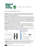
10� Slide the webcam arm into the lower part of the
elbow arm assembly. The webcam arm slides 12” into
the elbow assembly.
11� Ensure the webcam is on the top of the webcam arm
and tighten the arm set bolts.
• For a 10’-arm, the webcam arm bolts must feed through the pivoting arm, the
6’-arm section and the 10’-arm section. This sets the webcam 10’ from the display
face.
• For a 20’-arm, insert one set of bolts through the pivoting arm and the 6’-arm
section. Insert a second set of bolts on the end of the 6’-arm section away from
the display face and at the base of the 10’-arm section. This sets the webcam 15’
from the display face.
Bolt,
Nut,
Washer
Mounting
Channel
Figure 23: 10-20' Fixed Webcam
Arm Mounting
Bolting Template
Figure 24: Webcam Bolting
Template

Webcam Mounting
16
12� Tighten all mounting and webcam assembly bolts.
13� Connect the webcam cable to the Primary Webcam
connection below the power entrance box on the
back of the display.
14� Secure the green webcam grounding wire to the
grounding lug near the end of the display back. Refer
to Figure 25.
15� Neatly secure excess grounding wire with cable ties.
16� Ensure all webcam and webcam mounting bolts are
secure prior to hanging the display.
17� After hanging the display, connecting display power,
and starting the display, call Daktronics NOC and
have a technician verify they can detect the video
server. If the video server is not detected, ensure the
power and signal cables are securely attached to
the camera and display. Make sure the video server
has power and is connected with Cat-5e cable to the
network switch on the router.
18� Work with the NOC to ensure the camera is aligned properly. If adjustment is
required, pivot the arm to the display face and adjust as needed.
Optional Retracting the Webcam Arm
1� To retract the webcam arm, remove the two
short bolts from the top of the elbow assembly
and loosen the third bolt that is located in the
slot for rotation.
Note: Do not remove the long bolts.
2� Use the handle to carefully pivot the webcam
arm to the front catwalk.
Note: Verify that power and signal cables
are not pinched when pivoting the
webcam arm.
3� Return the webcam arm to the original
position when done servicing the webcam
arm.
4� Replace and tighten the three short bolts.
5� Work with Daktronics NOC to verify the
webcam is focused and functioning properly.
Figure 25: Webcam Ground Lug
Nut (x2)
Bolting Template
Bolt
Mounting
Channel
Remove Bolts
to Retract
Webcam Arm
Figure 26: Pivoting Webcam Arm Base
/