Page is loading ...

Ruckus Wireless
TM
ZoneFlex
TM
7731
802.11n Wireless Bridge
Installation Guide
Part Number 800-70236-001 Rev G
Published March 2013
www.ruckuswireless.com


i
Contents
1 About This Installation Guide . . . . . . . . . . . . . . . . . . . . . . . . . . . . . . . . . . . . . . . . . . . . . . . . 1
Related Documentation . . . . . . . . . . . . . . . . . . . . . . . . . . . . . . . . . . . . . . . . . . . . . . . . . . . 1
Documentation Feedback . . . . . . . . . . . . . . . . . . . . . . . . . . . . . . . . . . . . . . . . . . . . . . . . . 1
2 Unpacking the ZoneFlex Wireless Bridge. . . . . . . . . . . . . . . . . . . . . . . . . . . . . . . . . . . . . . . 2
Package Contents . . . . . . . . . . . . . . . . . . . . . . . . . . . . . . . . . . . . . . . . . . . . . . . . . . . . . . . . 2
3 Before You Begin . . . . . . . . . . . . . . . . . . . . . . . . . . . . . . . . . . . . . . . . . . . . . . . . . . . . . . . . . . 5
Prepare the Required Hardware and Tools . . . . . . . . . . . . . . . . . . . . . . . . . . . . . . . . . . . 5
Get to Know the Hardware Features . . . . . . . . . . . . . . . . . . . . . . . . . . . . . . . . . . . . . . . . . 5
4 Preparing for Installation . . . . . . . . . . . . . . . . . . . . . . . . . . . . . . . . . . . . . . . . . . . . . . . . . . . . 9
Summary of Configuration Tasks . . . . . . . . . . . . . . . . . . . . . . . . . . . . . . . . . . . . . . . . . . . . 9
What You Will Need . . . . . . . . . . . . . . . . . . . . . . . . . . . . . . . . . . . . . . . . . . . . . . . . . . . . . 10
Point to Point Bridge Configuration . . . . . . . . . . . . . . . . . . . . . . . . . . . . . . . . . . . . . . . . 11
Point to Multipoint Configuration . . . . . . . . . . . . . . . . . . . . . . . . . . . . . . . . . . . . . . . . . . 20
5 Physical Installation . . . . . . . . . . . . . . . . . . . . . . . . . . . . . . . . . . . . . . . . . . . . . . . . . . . . . . . . 23
Prepare the Required Hardware and Tools . . . . . . . . . . . . . . . . . . . . . . . . . . . . . . . . . . 23
Determine the Optimal Mounting Location and Orientation . . . . . . . . . . . . . . . . . . . . 24
Become Familiar with the Installation Components . . . . . . . . . . . . . . . . . . . . . . . . . . . 25
Decide How You Will Supply Power to the Wireless Bridge . . . . . . . . . . . . . . . . . . . . . 26
Deploying the Wireless Bridge . . . . . . . . . . . . . . . . . . . . . . . . . . . . . . . . . . . . . . . . . . . . 29
Attaching the Mounting Brackets . . . . . . . . . . . . . . . . . . . . . . . . . . . . . . . . . . . . . . . . . . 36
Mounting the Wireless Bridge . . . . . . . . . . . . . . . . . . . . . . . . . . . . . . . . . . . . . . . . . . . . . 43
Mounting and Connecting the External Antenna (Optional) . . . . . . . . . . . . . . . . . . . . 47
6 Optimizing the Distance, Orientation and Channel . . . . . . . . . . . . . . . . . . . . . . . . . . . . . 48
Setting the Distance . . . . . . . . . . . . . . . . . . . . . . . . . . . . . . . . . . . . . . . . . . . . . . . . . . . . . 48
Aiming . . . . . . . . . . . . . . . . . . . . . . . . . . . . . . . . . . . . . . . . . . . . . . . . . . . . . . . . . . . . . . . . 49
Channel Optimization . . . . . . . . . . . . . . . . . . . . . . . . . . . . . . . . . . . . . . . . . . . . . . . . . . . . 52

ii
7 Verifying the Connection . . . . . . . . . . . . . . . . . . . . . . . . . . . . . . . . . . . . . . . . . . . . . . . . . . . 54
8 What to Do Next. . . . . . . . . . . . . . . . . . . . . . . . . . . . . . . . . . . . . . . . . . . . . . . . . . . . . . . . . . 56
Change the Administrative Password . . . . . . . . . . . . . . . . . . . . . . . . . . . . . . . . . . . . . . . 56
Read Related Documentation . . . . . . . . . . . . . . . . . . . . . . . . . . . . . . . . . . . . . . . . . . . . . 56

1
About This Installation Guide
Related Documentation
1 About This Installation Guide
This Installation Guide provides information on how to set up the Ruckus Wireless ZoneFlex
7731 802.11n Point to Multipoint Wireless Bridge on your network. Topics covered in this
guide include installation, basic configuration, and device mounting.
This guide is intended for use by those responsible for installing and setting up network
equipment. Consequently, it assumes a basic working knowledge of local area networking,
wireless networking, and wireless devices.
Related Documentation
In addition to this guide, each Ruckus Wireless ZoneFlex 7731 802.11n Wireless Bridge
documentation set includes the following:
■ User Guide: Provides detailed information on how to configure the Wireless Bridge.
The User Guide is available for download on the Ruckus Wireless Support Web site at
http://support.ruckuswireless.com/documents
■ Release Notes: Provides late-breaking information about the current software release,
including new features, enhancements, and known issues. If the information in the
release notes differs from the information in this guide, follow the instructions in the
release notes.
■ Online Help: Accessible from the ZoneFlex 7731 web interface, the online help
provides information that helps you configure the device from the Web interface.
Documentation Feedback
Ruckus Wireless is interested in improving its documentation and welcomes your
comments and suggestions. You can email your comments to Ruckus Wireless at
When contacting us, please include the following information:
■ Document title
■ Document part number (on the cover page)
■ Page number (if appropriate)
For example:
■ ZoneFlex 7731 802.11n Wireless Bridge Installation Guide
■ Part number: 800-70236-001 Rev G
■ Page 24

2
Unpacking the ZoneFlex Wireless Bridge
Package Contents
2 Unpacking the ZoneFlex Wireless Bridge
1. Open the Wireless Bridge package, and then carefully remove the contents.
2. Return all packing materials to the shipping box, and put the box away in a dry location.
3. Verify that all items listed in Package Contents
below are included in the package.
Check each item for damage. If any item is damaged or missing, notify your authorized
Ruckus Wireless sales representative.
Package Contents
Each ZoneFlex 7731 package contains the following:
■ ZoneFlex 7731 Point to Multipoint Wireless Bridge
■ PoE injector box (excluded in some SKUs)
■ Power adapter box (SW DC48V/0.42A AC100-240V) for the PoE injector (excluded in
some SKUs)
■ Mounting kit (see “Mounting Kit Contents” for details)
■ Bag containing bottom Wireless Bridge cover and related accessories (see “Bottom
Cover and Accessories” for details)
■ Service Level Agreement / Limited Warranty Statement
■ Regulatory Statement
■ Declaration of Conformity
■ Registration Card
■ This Installation Guide
WARNING: The Ruckus Wireless PoE injector and power adapter (if supplied with your
Wireless Bridge) are for indoor use only. Never mount the PoE injector and power adapter
outdoors with the Wireless Bridge.

3
Unpacking the ZoneFlex Wireless Bridge
Package Contents
Mounting Kit Contents
■ Dynamic bracket
■ Static bracket
■ Steel clamps (2 pieces)
■ Hex bolts (2 pieces)
■ Flat washers (4 pieces)
■ Split lock washers (4 pieces)
■ Thumb screws (2 pieces)
■ M4 machine screws with washers (4 pieces)
■ Wall anchors (2 pieces)
■ Green/yellow earth ground wire with ring terminal
NOTE: Your mounting kit may include extra components to be used as spares.
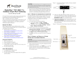
Figure 1. Mounting kit contents
Dynamic bracket Static bracket Steel clamp (2
pieces)
Hex bolt (2 pieces)
Flat washer (4
pieces)
Split lock washer (4
pieces)
Thumb screw (2
pieces)
Machine screw (4
pieces)
Wall anchor with
metal cone and
hex nut (2 pieces)
Earth ground wire
with ring terminal

4
Unpacking the ZoneFlex Wireless Bridge
Package Contents
Bottom Cover and Accessories
Each bottom cover accessory bag contains:
■ Bottom cover of the Wireless Bridge
■ DC terminal block
■ 20mm x 30mm sealing strips (2 pieces)
■ Sealing plug
■ White P-clip cable clamps (2 pieces - 1 large, 1 small)
■ Machine screws (2 pieces)
■ Machine screws with washers (3 pieces)
Figure 2. Bottom cover and accessory package contents
Bottom cover DC terminal block Sealing Plug (20 mm
long)
Sealing Strip (2
pieces)
White P-clip cable
clamp
Machine screw (2
pieces)
Machine screw with
O-ring and washer (3
pieces)

5
Before You Begin
Prepare the Required Hardware and Tools
3 Before You Begin
Prepare the Required Hardware and Tools
You must supply the following tools and equipment:
■ A notebook or desktop computer running Windows (2000/XP/Vista/7) with one
Ethernet card installed
■ 6mm flathead screwdriver
■ 6mm Phillips screwdriver
■ 10mm ratchet wrench
■ 3mm Phillips screwdriver (if you will be using DC power)
■ Electric drill with 8mm drill bit (if mounting on a flat surface)
Get to Know the Hardware Features
Figure 3 identifies the Wireless Bridge features that are relevant to the installation and
mounting instructions that this guide provides. Before you begin the installation process,
Ruckus Wireless recommends that you become familiar with these features.
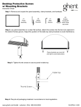
Figure 3. Wireless Bridge LEDs and bottom connectors
5
1
2
4
3

6
Before You Begin
Get to Know the Hardware Features
Table 1. LEDs and bottom panel connectors
No Label Description
1 LEDs See “LED Colors and What They Mean”
below for more
information.
2 RJ45 LAN port that supports Power over Ethernet (PoE) and 10/
100/1000 Mbps network connections.
3 Reset Using a pointed object (for example, a pen), press this
button to restart the Wireless Bridge or to restore it to
factory default settings:
• To restart the Wireless Bridge, press the Reset button
once.
• To restore the Wireless Bridge to factory defaults, press
and hold the Reset button for six (6) seconds.
WARNING: Restoring the Wireless Bridge to factory
default settings removes all configuration changes that
you have made. These include the IP address, password,
access control list, and wireless settings. Returning the
configuration of these features to their factory default
settings may result in network connectivity issues.
4 12V DC In addition to PoE, you can also use DC power (from a
battery, for example) to supply power to the Wireless
Bridge.
5 Aiming Button Press this button to set the Wireless Bridge to Aiming
Mode. When Aiming Mode is set, the LEDs can be used
to determine signal strength. See “Aiming Mode”
for
more information.

7
Before You Begin
Get to Know the Hardware Features
LED Colors and What They Mean
The ZoneFlex 7731 Wireless Bridge includes 6 dual color LEDs. The LEDs function in two
modes, normal operation mode and aiming mode.
Figure 4. LED Indicators
■ For Normal Operation Mode LED states and what they indicate, refer to Table 2 .
■ For Aiming Mode LED states and what they indicate, refer to Tab le 3 .
Normal Operation Mode
In Normal Operation Mode, the WLAN LED indicator is off when disconnected, flashing
green while connecting and solid green when a connection has been established.
Table 2. Normal Operation Mode LED indicators
LED Meaning
LED 1 (AIM/PWR) Solid Green = Power on
Off = Power off
LED 2 (LAN) Solid (Green / Orange / Yellow) = Link Up
Blinking (Orange / Green) = Activity
Off = Link Down
Green = Gigabit Ethernet (10/100/1000) full/half duplex
Orange = Fast Ethernet (10/100) full/half duplex
Yellow = Ethernet full/half duplex
LED 3 (WLAN) Solid Green = Associated
Blinking Green = Not Associated
Off = Radio Off
LED 4 (ROLE) Solid Orange = This unit is the Root Bridge
Off = This unit is the Non-Root Bridge
LED 1
LED 2
LED 3
LED 4
LED 5
LED 6

8
Before You Begin
Get to Know the Hardware Features
Aiming Mode
In Aiming Mode, LED 1 indicates that the Wireless Bridge is in Aiming Mode. LED
indicators 2 - 6 are used together to indicate signal strength, and should be read from
bottom to top (the higher the LEDs go, the stronger the signal).
In Aiming Mode, each LED has three states to represent different values. Solid yellow
indicates the highest value, flashing yellow indicates medium value and off indicates the
lowest value. If all six LEDs are solid yellow, the Wireless Bridge has the strongest signal
possible. If some LEDs are flashing yellow or off, reposition the Wireless Bridge to achieve
a better signal. For more detailed information on signal strength levels, see “RSSI values
of LED indicators” on page 50.
Push Buttons
The ZoneFlex 7731 includes two push buttons:
■ A recessed factory default reset button (located inside the bottom panel)
■ A large blue Aiming button that sets the bridge to Aiming Mode (located on the
outside of the unit)
To reset the unit to its factory defaults, press and hold the Reset button for six (6) seconds.
Press and hold the blue Aiming button for four (4) seconds to initiate aiming between the
Root and Non-Root Bridges.
LED 5 & 6 (P0 and P1) Alternating Blinking = Provisioning in process, role is unknown
Simultaneous Blinking = Provisioning complete; reboot pending
Table 3. Aiming Mode LED indicators
LED Meaning
LED 6 Signal strength 5
LED 5 Signal strength 4
LED 4 Signal strength 3
LED 3 Signal strength 2
LED 2 Signal strength 1
LED 1 (AIM/PWR) Solid Yellow = Aiming Mode (RSSI >= 5)
Solid Green = Normal Operation Mode
Off = Off
Table 2. Normal Operation Mode LED indicators
LED Meaning

9
Preparing for Installation
Summary of Configuration Tasks
CAUTION: Resetting the ZoneFlex 7731 to its factory defaults will result in loss of all
configuration settings, including the provisioning (pairing of the Root and Non-Root
Bridge) settings. If you do need to reset to defaults, you will need to re-provision the
bridge. In factory default state, the role of all 7731 units is Root Bridge. Therefore, running
the factory default procedure on any ZoneFlex 7731 results in that unit becoming
unreachable on the non-root bridge default IP address (192.168.2.254).
4 Preparing for Installation
This section describes the configuration procedures required before you proceed to
mount the ZoneFlex 7731 Wireless Bridge units in their permanent locations. These tasks
should be performed prior to connecting any ZoneFlex 7731 to your live network.
Summary of Configuration Tasks
If you have purchased the standard two unit package, the Root Bridge and Non-Root
Bridge will have already been preconfigured at the factory. Therefore, you will only need
to access both units and set the Country Code prior to installation (unless your country is
United States, in which case, Country Code is also preconfigured). Then you can go directly
to “Physical Installation”
.
If you have purchased a single Wireless Bridge, to expand your network to a point to
multipoint configuration, or replaced one of the units, or have decided to reset the units
to factory defaults for any reason, the following tasks should be performed prior to physical
installation:
1. Provision one ZoneFlex 7731 as the Root Bridge, and the remaining units as Non-Root
Bridges.
2. Access the Wireless Bridge Web interface using an administrative computer.
3. Set the country code to your current location.
4. Change other configuration settings (optional).
5. Verify association between the Root and Non-Root bridges.
NOTE: If you purchased your Wireless Bridge in the United States, the country code is
fixed to “United States” at the factory and is not user configurable. If not, you must set
the country code to your location prior to mounting to ensure compliance with national
regulatory requirements.

10
Preparing for Installation
What You Will Need
CAUTION: If changing the Country Code over the air, you will need to configure the
remote units first followed by the local unit, to avoid loss of connectivity.
In addition to setting the country code (required), the following optional configuration
settings may be changed at this time:
■ Change the device names, SSID, shared secret, user names and passwords
■ Manually assign static IP addresses
■ Enable SNMP or FlexMaster network management
■ Configure security settings
■ Configure management VLAN
To customize any of these settings before deploying the bridge pair, you will need to
connect an administrative computer directly to each ZoneFlex 7731, and provide power
using either DC power or Power over Ethernet before you can access the Web interface.
The default IP addresses for the Root and Non-Root Bridge are as follows:
■ Root Bridge: 192.168.2.1
■ Non-Root Bridge: 192.168.2.254
CAUTION: In factory default state, the role of all 7731 units is Root Bridge. Therefore,
running the factory default procedure on any ZoneFlex 7731 results in that unit becoming
unreachable on the non-root bridge default IP address (192.168.2.254).
What You Will Need
Before starting with the configuration tasks, make sure that you have the following
requirements ready:
■ An administrative computer running Microsoft Windows (2000/XP/Vista/7)
■ Microsoft Internet Explorer (6.0 or later) or other browser such as Firefox, installed on
the administrative computer
■ Two Ethernet cables (Cat-5e or better)
■ PoE injector (if not supplied with the Wireless Bridge, you can purchase a third party
802.3af-compliant PoE injector or switch)
■ 6mm Phillips screwdriver
If you are planning to power the Wireless Bridge using a 12 VDC connection, you will also
need the following:
■ One 3.1mm-3.3mm UL1185 (80°, 300V) single shielded DC cable
■ 12 VDC, 1A DC power source (for example, a battery)
■ 3mm Phillips screwdriver

11
Preparing for Installation
Point to Point Bridge Configuration
Point to Point Bridge Configuration
The following section provides instructions for configuring two ZoneFlex 7731 Wireless
Bridges for point to point bridging.
If you will be deploying more than one Non-Root Bridge, Ruckus Wireless recommends
first completing the Point to Point Bridge configuration, before proceeding to “Point to
Multipoint Configuration” on page 20.
CAUTION: Do not attempt to access the Web interface of two ZoneFlex 7731 units at the
same time by connecting both to the same Layer 2 switch or to the same broadcast domain
on a live network. This will cause a network loop, which can disrupt your entire network.
Step 1: Supply Power to the Wireless Bridge
This procedure assumes that you will be using Power over Ethernet for the pre-installation
configuration, even if you plan to use DC power in the final deployment. For DC power
setup, see “Use DC Power”
on page 32.
NOTE: You only need to connect one type of power source at this point, even if you are
planning to use both PoE and DC power in your final deployment.
Use Power Over Ethernet
1. Take out the PoE injector and the power adapter from the Wireless Bridge package.
2. Obtain two Ethernet cables.
3. Connect one end of one Ethernet cable to the AP/BRIDGE port on the PoE injector,
and then connect the other end to the RJ45 port on the ZoneFlex 7731.
4. Connect one end of the other Ethernet cable to the NETWORK port on the PoE
injector.
5. Connect the power jack to the DC 48V IN connector on the PoE injector, and then
plug the power adapter into a power source. The single LED on the PoE injector turns
red.
6. Check the power LED on the ZoneFlex 7731 to ensure power is being supplied to the
bridge.

12
Preparing for Installation
Point to Point Bridge Configuration
Figure 5. Connect the Ethernet cables and power adapter to the PoE injector
You have completed connecting the Wireless Bridge to a PoE power source.
Step 2: Auto Provision the Root and Non-Root Bridges
The first configuration task (after you have supplied power) involves provisioning one
ZoneFlex 7731 as the Root Bridge and the others as Non-Root Bridges. Two methods are
available:
■ Auto Provisioning
■ Manual Provisioning
Auto Provisioning
When in factory default state, you can designate one ZoneFlex 7731 as a Root Bridge and
another as a Non-Root Bridge by simply providing power to both units and connecting
them directly to each other with an Ethernet cable. This Auto Provisioning process chooses
the device with the lower MAC address and provisions it as the Root Bridge, while the
device with the higher MAC address is automatically provisioned as the Non-Root Bridge.
If you want to have more control over which is the Root and Non-Root Bridge, you should
choose Manual Provisioning
.
Auto provisioning can only be performed on two ZoneFlex 7731 units - if you will be using
more than two, you will need to manually provision the third unit.
To Auto Provision two ZoneFlex 7731 Wireless Bridges
1. Provide power to both bridges and connect them together directly via an Ethernet
cable (you can power up and then connect, OR connect and then power up both units).
2. The LAN LED on both units (LED 2) should be solid green, indicating that the units are
connected to each other. At this point, if both units have been reset to factory defaults,
neither has yet been provisioned as Root or Non-Root.
To Admin
Computer
To Bridge
To AC Powe r Sourc e

13
Preparing for Installation
Point to Point Bridge Configuration
3. Once both units are powered on and physically connected, LED 5 and 6 (labeled P0
and P1) on both units begin alternately blinking, indicating that the role is unknown
and provisioning is in process. This process takes about 10 to 20 seconds.
4. Simultaneous rapid blinking of these two LEDs indicates that provisioning is complete.
5. After provisioning is complete, LED 4 (ROLE) indicates which unit is the Root and Non-
Root unit. The ROLE LED is solid yellow for the Root Bridge while the Non-Root
Bridge’s ROLE LED is OFF.
6. Take note of which unit is the Root Bridge and which is the Non-Root Bridge.
7. When the auto provisioning process is complete, you must reboot both units. A reboot
is triggered by disconnecting the Ethernet cable.
8. During the reboot only the bottom LED, PWR is lit. Once the reboot completes you
will see activity on the WLAN LED, indicating wireless communication between the
pair.
You have completed auto provisioning the Root and Non-Root Bridge pair.
Figure 6. Auto Provisioning a Root Bridge and a Non-Root Bridge
Step 3: Prepare the Administrative Computer
NOTE: The following procedure is applicable if the administrative computer is running
Windows XP or Windows 2000. If you are using a different operating system, refer to the
documentation that was shipped with your operating system for information on how to
modify the computer’s IP address settings.
PoE
Injector
PoE
Injector
Connect Directly via
Ethernet Cable to Auto
Provision
To AC Power
Source
To AC Power
Source

14
Preparing for Installation
Point to Point Bridge Configuration
1. On your Windows XP or Windows 2000 computer, open the Network Connections (or
Network and Dial-up Connections) control panel according to how the Start menu is
set up:
• On Windows XP, click Start > Control Panel > Network Connections.
• On Windows 2000, click Start > Settings > Network Connections.
2. When the Network Connections window appears, right-click the icon for Local Area
Connection, and then click Properties.
NOTE: Make sure that you configure the Local Area Connection properties, not the
Wireless Network Connection properties.
3. When the Local Area Connection Properties dialog box appears, select Internet
Protocol (TCP/IP) from the scrolling list, and then click Properties. The Internet
Protocol (TCP/IP) Properties dialog box appears.
4. Write down all of the currently active network settings. You will need this information
later when you restore your computer to its current network configuration.
5. Click Use the following IP address, and then configure the IP address settings with
the values listed in Tabl e 4
. For a sample configuration, refer to Figure 7.
You can leave the Default Gateway and DNS fields blank.
6. Click OK to save your changes and close the TCP/IP Properties dialog box.
7. Click OK again to close the Local Area Connection Properties dialog box.
Windows saves the IP address settings that you have configured. Your admin computer is
now ready for direct connection with the ZoneFlex 7731.
Table 4. Configure your computer’s IP address settings
IP address 192.168.2.22 (or any address in the 192.168.2.x
network—with the exception of 192.168.2.1 and
192.168.2.254 which will be used by the bridges)
Subnet mask 255.255.255.0

15
Preparing for Installation
Point to Point Bridge Configuration
Figure 7. Sample configuration in the Internet Protocol (TCP/IP) Properties dialog box
Step 4: Connect the Wireless Bridge to the Admin
Computer
If you have not already done so, connect the admin computer to the ZoneFlex 7731 using
an Ethernet cable, or two Ethernet cables and a PoE injector if you are using Power over
Ethernet (see “Connect the Ethernet cables and power adapter to the PoE injector”
on
page 12
).
Step 5: Log In to the Web Interface
1. Open a Web browser window from the admin computer.
2. In the address or location bar, type the following address:
Root Bridge: http://192.168.2.1
Non-Root Bridge: http:/192.168.2.254
3. Press <Enter> on the keyboard to connect to the Wireless Bridge’s Web interface. A
security alert message appears.
4. Click Yes or OK (depending on the browser) to continue. The Wireless Bridge’s login
page appears.

16
Preparing for Installation
Point to Point Bridge Configuration
Figure 8. The ZoneFlex Wireless Bridge login page
5. In User name, type super.
6. In Password, type sp-admin.
7. Click Login. The Web interface appears, displaying the Status > Wireless page.
Figure 9. Ruckus ZoneFlex 7731 Wireless Bridge Status :: Wireless page
8. Continue to “Step 6: Change the Country Code”
.
/