Dwyer Series TSW User manual

Category
Security access control systems
Type
User manual

Dwyer Series TSW is a digital temperature switch that combines reliability and a user-friendly weatherproof enclosure, enabling installation in various environments. Its compatibility with Series TS2 and Series TSS2 programming parameters allows for quick setup using front keys or the TS2-K configuration key. To prevent unauthorized tampering, a parameter lock jumper and software passcode security are integrated. Features include a bright LED display, multiple conduit knockouts for flexible installation, and the ability to jumper line voltage to the common of the output relay using fast tabs.

Dwyer Series TSW is a digital temperature switch that combines reliability and a user-friendly weatherproof enclosure, enabling installation in various environments. Its compatibility with Series TS2 and Series TSS2 programming parameters allows for quick setup using front keys or the TS2-K configuration key. To prevent unauthorized tampering, a parameter lock jumper and software passcode security are integrated. Features include a bright LED display, multiple conduit knockouts for flexible installation, and the ability to jumper line voltage to the common of the output relay using fast tabs.

T
he Series TSW Digital Temperature Switch combines the trusted, reliable TS
f
amily of temperature controls and an installation friendly weatherproof enclosure.
B
y using the same programming parameters as our Series TS2 and Series TSS2,
set up can be quickly completed using the front keys or by using the TS2-K con-
figuration key. In order to prevent tampering from unauthorized users, a parame-
ter lock physical jumper and software passcode security are standard in the unit.
The bright, easy-to-read LED display shows the current output status and the tem-
perature measurement.
The multiple conduit knockouts on the Series TSW give flexibility to the installer to
determine the best location for the conduit entry. Another installation friendly fea-
ture of the Series TSW is the ability to quickly jumper the line voltage to the com-
mon of the output relay using fast tabs.
INSTALLATION
NOTICE: The thermostat must be installed by authorized professionals. It should
be located in a place free of vibrators, impacts, and corrosive gases.
NOTICE: Protective plastic overlay should be peeled off after final installation.
Series TSW Dual Stage Digital Temperature Switch
Specifications - Installation and Operating Instructions
Bulletin T-TSW-2
SPECIFICATIONS
Probe Range:
P
TC: -58 to 302°F (-50 to 150°C).
NTC: -58 to 230°F (-50 to 110°C).
Input: PTC (1000 Ω @ 25°C)/NTC (10KΩ @ 25°C).
Output: R1 SPDT Relay Resistive Load: 20A @ 240 VAC; R2 SPDT Relay
Resistive Load: 8A @ 240 VAC, Inductive Load: 3A @ 240 VAC.
Horsepower Rating: R1 2HP @ 240 VAC.
Control Type: On/Off.
Power Requirements: 90 to 255 VAC or 12 to 24 VAC/VDC (±10%) depending
on model.
Power Consumption: 3.6VA.
Accuracy: ±1% FS.
Display: 3 digits plus sign.
Resolution: .1° < 100°; 1° ≥ 100°.
Memory Backup: Non-volatile memory.
Ambient Temperature: 32 to 104°F (0 to 40°C).
Weight: 1.2 lbs (544 g).
Front Protection: NEMA 4X (IP66).
Agency Approvals: CE, UL, cUL.
2-19/32
[
65.53]
3
-5/8
[92.08]
6
-21/32
[
168.91]
DWYER INSTRUMENTS, INC.
Phone: 219/879-8000 www.dwyer-inst.com
P.O. BOX 373 MICHIGAN CITY, INDIANA 46360, U.S.A. Fax: 219/872-9057 e-mail: [email protected]
W
IRING INSTRUCTIONS
W
iring diagram is displayed on the inside cover of the unit and in figure 1.
N
OTICE: If the length of the probe cables measures more than 100 meters, a recal-
ibration adjustment must be made (parameter P1).
NOTICE: Avoid installing the probe cables in proximity with any power cables.
P
ROGRAMMING PARAMETERS
I
n order to adjust parameter values, parameter lock jumper must be set in unlocked
p
osition (see figure 2).
Access only to Set Points SP1 and SP2 (without code protection):
• Press SET key. Out1 LED and out1 set point value will flash on the
display.
• Modify the out1 set point value using the UP and DOWN keys.
• Press SET key to store the out1 set point value and advance to out2
set point value.
• Modify the out2 set point value using the UP and DOWN keys.
• Press SET key to store the value and return to home screen.
Access to all parameters (code protected):
• Press SET for 8 seconds. The access code value 0 is shown on the
display.
• Using the UP and DOWN buttons, set the code (factory-set code is
0).
• Press SET to confirm the code. If it is correct, the first parameter label will be
shown on the display (SP1).
• Move to the desired parameter with the UP and DOWN keys.
• Press SET to see the value of the parameter.
• Modify the value with the UP and DOWN keys.
• Press SET to store value.
• Press SET and DOWN to quit programming, or wait 1 minute for the TIMEOUT.
Resetting the parameter pass code
The parameter code can be set to zero by holding the SET key and turning the con-
troller off then on again.
LED INDICATIONS
Out1: Indicates relay 1 On or Off as per parameter H2. If H2=dir, with relay 1 On,
LED lit, if H2=inv, with relay 1 On, LED off. It blinks when SP1 is displayed.
Out2: Indicates relay 2 On or Off as per parameter H3. If H3=dir, with relay 2 On,
LED lit, if H3=inv, with relay 2 On, LED off. It blinks when SP2 is displayed.
Error Messages
Under normal operation, the temperature of the probe selected by P4 will be dis-
played, the following messages may also appear:
• Err Memory reading error.
• ErP Error of the probe not shown on the display.
• AH1 Maximum temperature alarm, probe 1.
• AL1 Minimum temperature alarm, probe 1.
• AH2 Maximum temperature alarm, probe 2.
• AL2 Minimum temperature alarm, probe 2.
• ooo Open probe.
• --- Shorted probe.
P
ressing SET and UP keys simultaneously will display the temperature of the probe
n
ot selected by P4 will be displayed. When the probe not selected by P4 is dis-
p
layed, it alternates its value with message Sd1 or Sd2 depending if it is probe 1 or
p
robe 2. Pressing SET and DOWN keys simultaneously will cancel. The display
blinks when waiting for a value confirmation.
Silence the Buzzer
P
ressing the SET and DOWN keys simultaneously silences the buzzer. The mes-
s
age of alarm continues appearing in the display.
R
esetting Parameters to Factory Values
• Access parameter H0 as explained in programming parameters.
• Value 0 will be displayed.
• Press SET for 8 seconds. Pro will be displayed if they have been setup
c
orrectly.
Press SET + DOWN to exit setup or wait for 1 minute.
S
P1
S
P2
r0
r1
r2
r3
r
4
r
5
r
6
r7
r8
A0
A1
A
2
A3
A4
A5
A6
A7
c0
c1
c2
c3
c4
P0
P1
P2
P3
P4
P5
H0
H1
H2
H3
H4
H5
H6
Description
S
et point 1
S
et point 2
Dependency SP1 to SP2
Differential for SP1
Differential for SP2
Band differential
L
owest value for SP1
L
owest value for SP2
H
ighest value for SP1
Highest value for SP2
Regulation or Operating Mode
Alarm Differential
Maximum alarm probe 1
M
aximum alarm probe 2
Minimum alarm probe 1
Minimum alarm probe 2
Alarm verification time
Alarm probe 1 selection
Alarm probe 2 selection
Minimum relay stop time
Operation relay 1
Operation relay 2
Fail Safe Operation relay 1
Fail Safe Operation relay 2
Temperature Units Selection
Calibration Probe 1
Calibration Probe 2
Decimal Point
Probe to be displayed
Number of Probes
Factory Reset Values
Keypad tamper protection
Operation of Out1 LED
Operation of Out2 LED
Address for serial communication
Access code to parameters
Probe Type Selection
Units
D
egrees
D
egrees
Option
Degrees
Degrees
Degrees
D
egrees
D
egrees
D
egrees
Degrees
Option
Degrees
Degrees
D
egrees
Degrees
Degrees
h-m(*)
Option
Option
Minutes
Option
Option
Option
Option
Option
Degrees
Degrees
Option
Option
Option
Option
Option
Option
Option
Range
Range
Option
Range
r
4 to r6
r
5 to r7
Ind or dep
0.1 to 20.0
0.1 to 20.0
0.1 to 20.0
-
99.9 to r6
-
99.7 to r7
r
4 to 302
r5 to 302
On1, On2, nEU
0.1 to 20.0
0.1 to 99.9
0
.1 to 99.9
0.1 to 99.9
0.1 to 99.9
0.0 to 18.0
AHL, Ano, AH, AL
AHL, Ano, AH, AL
0 to 240
dir or inv
dir or inv
Opn or Clo
Opn or Clo
°C or °F
-20 to 20
-20 to 20
no or yes
sd1 or sd2
1 or 2
0
no or yes
dir or inv
dir or inv
0-999
0-999
Ptc or ntc
Factory
V
alue
1
0.0
1
0.0
ind
1.0
1.0
1.0
-
99.9
-
99.9
3
02
302
On1
0.1
99.9
9
9.9
99.9
99.9
18.0
AHL
AHL
O
dir
dir
Opn
Opn
°C
0.0
0.0
yes
sd1
1
0
no
dir
dir
0
0
PTC
(*) h-m are data in format XX.Y where XX are hours and Y tens of minutes.
PROBE
INPUTS
1 2 3 4 5 6 7 8 9 10 11
OUTPUTS
OUT 2
Sd2 Sd1
TS2-K
O
UT 1
POWER
SUPPLY
Figure 1
F
igure 2
Locked Unlocked
P
arameter List
P
ARAMETER DESCRIPTIONS
S
P1=Setpoint of relay1. Variable between r4 and r6.
S
P2=Setpoint of relay 2. Variable between r5 and r7.
r
0=Dependency between SP1 and SP2. Only for mode ONOFF1
Ind=set point for relay 2, SP2.
dep=set point for relay 2, SP1+SP2.
r1=Differential or hysteresis for relay 1. Temperature differential between ON/OFF
o
f relay 1 in ON/OFF control.
r
2=Differential or hysteresis for relay 2. Temperature differential between ON/OFF
o
f relay 2 in ON/OFF control.
r
3=Band differential. Temperature differential between ON/OFF of relays 1 and 2 in
neutral area control. For relay 1 it is added to SP1 and for relay 2 it is subtracted
from SP1.
r4=Lowest value for SP1.
r
5=Lowest value for SP2.
r
6=Highest value for SP1.
r
7=Highest value for SP2.
r8=Regulation or operating mode. Selection of the operating mode.
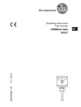
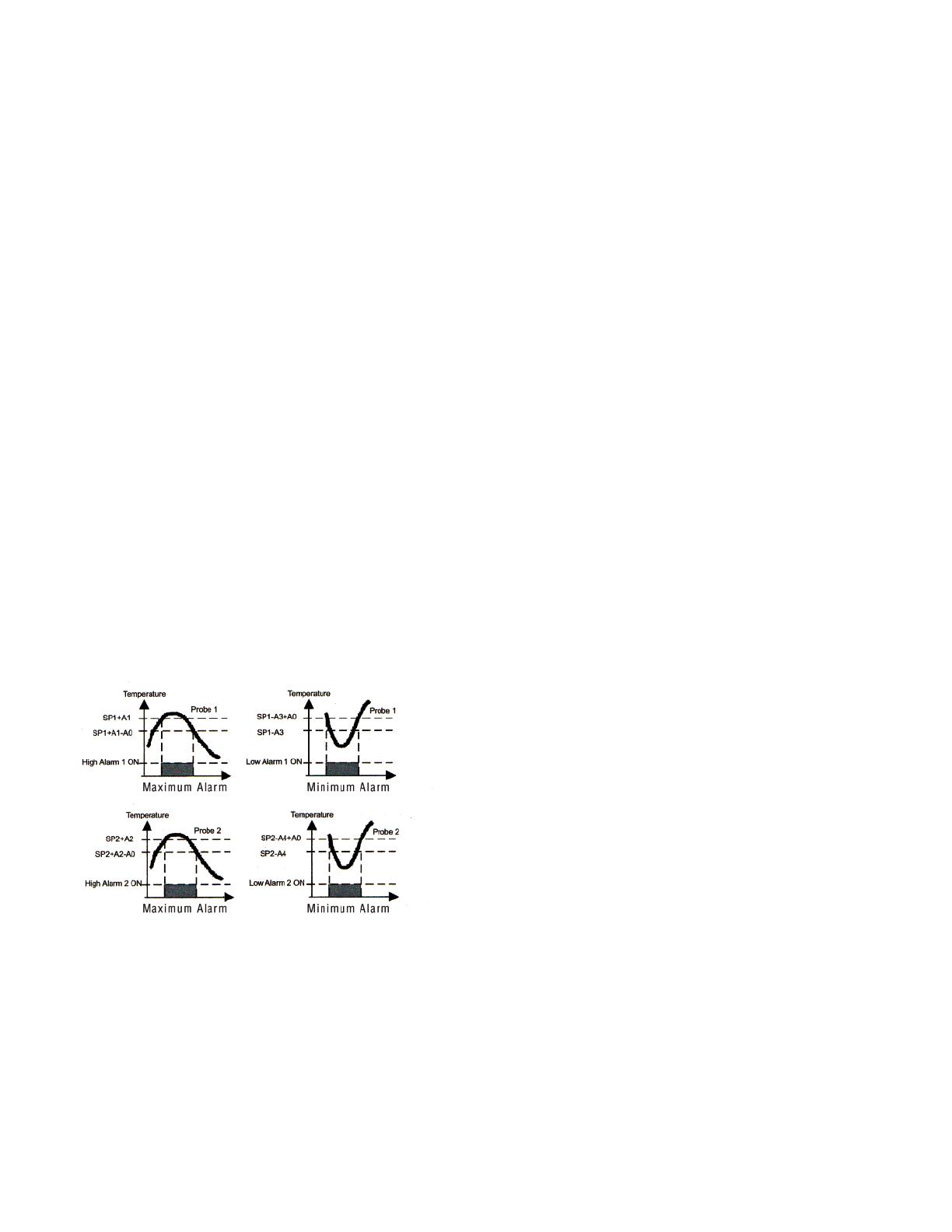
A0=Alarm differential. It is the temperature differential between the alarm On and
Off cycle.
A1=Maximum alarm probe1.
M
aximum alarm ON when probe 1 higher than SP1+A2
M
aximum alarm OFF when probe 1 lower than SP1+A2-A0.
A
2=Maximum alarm probe2.
Maximum alarm ON when probe 2 higher than SP2+A2
Maximum alarm OFF when probe 2 lower than SP2+A2-A0.
A3=Minimum alarm probe1.
Minimum alarm ON when probe 1 lower than SP1-A3
M
inimum alarm OFF when probe 1 higher than SP1-A3+A0.
A
4=Minimum alarm probe2.
M
inimum alarm ON when probe 2 lower than SP2-A4
Minimum alarm OFF when probe 2 higher than SP2-A4+A0.
A5=Alarm verification time. Time from the alarm event until it trips.
A6=Alarm probe 1 selection. (See Figure 3).
AHL=Maximum and minimum alarm probe 1 enabled.
Ano=No alarms probe 1.
AH=Maximum alarm probe 1 enabled.
AL=Minimum alarm probe 1 enabled.
A7=Alarm probe 2 selection. (See Figure 3).
AHL=Maximum and minimum alarm probe 2 enabled.
Ano=No alarms probe 2.
AH=Maximum alarm probe 2 enabled.
AL=Minimum alarm probe 2 enabled.
c
0 = Minimum relay stop time. Minimum time from the disconnection of a relay until
i
t can be switched on again.
c1 = Operation relay 1. Selection between direct or reverse operation for relay 1.
c2 = Operation relay 2. Selection between direct or reverse operation for relay 2.
c3 = Default operation relay 1. In case of failure of probe 1:
o
Pn= relay 1 will remain open.
C
lo= relay 1 will remain closed.
c
4 = Default operation relay 2. In case of failure of probe 1 (for all modes except-
i
ng ON OFF2) or in case of failure of probe 2 (for mode ON OFF2):
oPn= relay 2 will remain open.
Clo= relay 2 will remain closed.
P0 = Temperature scale selection.
P
1 = Calibration of probe 1. Offset degrees to be added to probe 1.
P
2 = Calibration of probe 2. Offset degrees to be added to probe 2.
P
3 = Decimal point. If the displayed value of the probes is desired with decimals or
not.
P4 = Probe to be displayed. Probe always on the display. The other probe can be
seen pressing the keys SET+UP.
sd1= probe 1.
s
d2= probe 2.
P
5 = Number of probes. If P5=1, there is no ONOFF2 mode. If selected, it will oper-
a
te as ONOFF1.
H0 = Reprogramming. Parameter to reprogram the thermostat.
H1 = Keyboard protection.
To change the settings, enter into parameter and exit again. The protection setting
is momentarily released. It switches on again 1 minute after the last time a key was
p
ressed.
Y
es = Keyboard Protected.
N
o = Keyboard non protected.
H2 = Operation of LED OUT1.
dir = On when relay 1 is ON.
inv = On when relay 1 is OFF.
H3 = Operation of LED OUT2.
dir = On when relay 2 is ON.
inv = On when relay 2 is OFF.
H4 = Serial communication address. Address for computer connection.
H5 = Parameter entry code. Factory set as 0.
MAINTENANCE
After final installation of the TSW Series Digital Temperature Switch, no routine
maintenance is required. A periodic check of system calibration is recommended.
The devices are not field repairable and should be returned to the factory if recali-
bration or other service is required. After first obtaining a Returned Goods
Authorization (RGA) number, send the material, freight prepaid, to the following
address. Please include a clear description of the problem plus any application
information available.
Dwyer Instruments, Inc.
Attn: Repair Department
102 Highway 212
Michigan City, IN 46360 U.S.A.
Figure 3
O
perating modes
M
ode ON OFF1 (On1) with r0=ind.
R
elay 1 with c1=dir.
T
emperature of probe 1 >= SP1+r1 -->relay 1 ON
Temperature of probe 1 <= SP1 -->relay 1 OFF
R
elay 1 with c1=inv.
Temperature of probe 1 <= SP1-r1 -->relay 1 ON
Temperature of probe 1 >= SP1 -->relay 1 OFF
R
elay 2 with c2=dir.
Temperature of probe 1 >= SP2+r2 -->relay 2 ON
Temperature of probe 1 <= SP2 -->relay 2 OFF
Relay 2 with c2=inv.
Temperature of probe 1 <= SP2-r2 -->relay 2 ON
Temperature of probe 1 >= SP2 -->relay 2 OFF
Mode ON OFF1 (On1) with r0=dep.
Output 1 works as an independent ON/OFF control (Figure 1 and 2),
but output 2 works as follows:
Relay 2 with c2=dir.
Temperature of probe 1 >= SP1+SP2+r2 -->relay 2 ON
Temperature of probe 1 <= SP1+SP2 -->relay 2 OFF
R
elay 2 with c2=inv.
T
emperature of probe 1 <= SP1+SP2-r2 -->relay 2 ON
T
emperature of probe 1 >= SP1+SP2 -->relay 2 OFF
M
ode ON OFF2 (On2)
O
utput 1 works as an independent ON/OFF control (Figure 1 and 2), but output 2
w
orks as follows:
Relay 2 with c2=dir.
Temperature of probe 2 >= SP2+r2 -->relay 2 ON
Temperature of probe 2 <= SP2 -->relay 2 OFF
R
elay 2 with c2=inv.
Temperature of probe 2 <= SP2-r2 -->relay 2 ON
Temperature of probe 2 >= SP2 -->relay 2 OFF
Neutral Area Mode (nEU)
Relay 1
Temperature of probe 1 >= SP1+r3 -->relay 2 ON
Temperature of probe 1 <= SP1 -->relay 2 OFF
Relay 2
Temperature of probe 1 <= SP1-r3 -->relay 2 ON
Temperature of probe 1 >= SP1 -->relay 2 OFF
Operation in case of error.
If probe 1 fails, the operation is through c3. (See Parameter description.)
If probe 2 fails, the operation is through c4. (See Parameter description.)
In case of memory failure, both relays will remain open.
©Copyright 2014 Dwyer Instruments, Inc. Printed in U.S.A. 7/14 FR# R0-443773-50 Rev. 3
DWYER INSTRUMENTS, INC.
Phone: 219/879-8000 www.dwyer-inst.com
P.O. BOX 373 MICHIGAN CITY, INDIANA 46360, U.S.A. Fax: 219/872-9057 e-mail: [email protected]
  • Page 1 1
  • Page 2 2
  • Page 3 3
  • Page 4 4

Dwyer Series TSW User manual

Category
Security access control systems
Type
User manual

Dwyer Series TSW is a digital temperature switch that combines reliability and a user-friendly weatherproof enclosure, enabling installation in various environments. Its compatibility with Series TS2 and Series TSS2 programming parameters allows for quick setup using front keys or the TS2-K configuration key. To prevent unauthorized tampering, a parameter lock jumper and software passcode security are integrated. Features include a bright LED display, multiple conduit knockouts for flexible installation, and the ability to jumper line voltage to the common of the output relay using fast tabs.

Ask a question and I''ll find the answer in the document

Finding information in a document is now easier with AI