Salsbury Industries 3716D-20AFU Installation guide

Type
Installation guide
IMPORTANT !
With its quality design and construction, Salsbury Industries’ 3700 series USPS approved 4C recessed mounted horizontal mailboxes will provide years
of maintenance free service. These units meet all the requirements of USPS STD-4C, the new high-security standard developed by the United States
Postal Service.
TYPICAL INSTALLATION
Have mailboxes and instructions on hand before
starting wall construction.
Unpack and review contents of shipping cartons.
Gather tenant and parcel locker keys and store in a
secure place.
Read installation instructions document thoroughly.
Determine rough opening size(s).
Determine rough opening location above finished floor.
Determine framing configuration and location.
Procure materials for wall construction.
Although these mailboxes have been tested and
approved for both outdoor and indoor use, some
shelter from direct weather conditions should be
provided, especially in areas with heavy rainfall. This
provides protection for the mail, the delivery personnel,
and the mail patrons.
The mailboxes are shipped fully assembled.
Hardware is included to fasten each unit into a wood
framed wall.
Trim is an integral part of the mailbox assembly. There
is no other snap on trim to install.
The floor of the lowest patron mailbox shall be no less than 28”
above the finished floor (AFF).
The patron lock in the highest mailbox shall be no more than 67” above the
finished floor.
The USPS Arrow lock (master door lock) opening must be a minimum of
36” and a maximum of 48” above the finished floor.
The floor of the lowest parcel locker shall be no less than 15” above the
finished floor.
The master access door(s) must be allowed to open a minimum of 90
degrees with no obstruction.
There must be at least one parcel locker for every ten patron mailboxes in
installations of 10 or more patron mailboxes. Parcel lockers must be a
minimum of 15” high (PL4.5, PL5 and PL6) to meet the 1:10 ratio. Once
this ratio has been met, smaller parcel lockers (PL3 and PL4) may also be
added. There is no requirement for parcel lockers in installations of less
than 10 patron mailboxes, but one or more parcel lockers is recommended.
PREPARATORY STEPS
1.
2.
3.
4.
5.
6.
7.
8.
NOTES
1.
2.
3.
4.
USPS REGULATIONS
The mailboxes must be installed according to Postal Regulations.
1.
2.
3.
4.
5.
6.
4C recessed mounted horizontal mailboxes can be
installed either with the included connector kits (see
instructions on pages 2-5) or separately with indi-
vidual wall framing (see page 6).
After installing the unit, contact your local postmaster – the USPS will provide and install its own master lock
on your mailbox unit. Hardware and instructions for installing the master lock are included inside the unit.
Please provide the hardware and instructions to the USPS representative when they arrive to install the lock.
U.S.P.S. APPROVED
Installation instructions are provided as general guidelines. It is advised that a professional installer be consulted. Salsbury Industries assumes
no product assembly or installation liability. Copyright © 2015 Salsbury Industries. All rights reserved. (Rev. 20, 02/10/2017)
SALSBURY INDUSTRIES
1010 East 62nd Street, Los Angeles, CA 90001-1598
Phone: 800-624-5269 Int’l Phone: 323-846-6700 Fax: 800-624-5299 Int’l Fax: 323-846-6800
www.mailboxes.com [email protected]
Page 1 of 6
67” AFF -
HIGHEST
POSITION
FOR PATRON
LOCK
48” AFF -
HIGHEST
POSITION FOR
AT LEAST
(1) PATRON
COMPARTMENT
48” AFF
36” AFF
CARRIER DOOR
ACCESS LOCK MUST
FALL BETWEEN
THESE DIMENSIONS
28” AFF -
LOWEST
PATRON
SHELF
SURFACE
15” AFF -
LOWEST
PARCEL
LOCKER
SHELF
SURFACE
FINISHED
FLOOR
CARRIER
ACCESS
DOOR LOCK
4C Recessed Mounted Horizontal Mailboxes – 3700 Series
FRONT LOADING Installation Instructions
Figure 1
4C Recessed Mounted Horizontal Mailboxes – Connector Kit
Front Loading Unit Installation Instructions
Rough Opening
Height: See chart on page 6.
Width: To establish the size of the rough opening(s) in the wall(s) you
will be installing your mailbox configuration(s) into, calculate the overall
width of the total amount of units per wall installation; then subtract 3/4”
from the width grand total.
Example: (2) double-column mailboxes are to be installed.
• Each unit is 31-1/8” wide x 2 units = 62-1/4”
• 62-1/4” - 3/4” = 61-1/2” required for rough opening.
STEP 1
Place the first unit into the rough opening (see figure 1). Open the master door(s) to locate the 2x4 mounting holes on the inside corner of the mailbox’s trim
panel (see figure 2 for the difference between the 2x4 mounting holes and the connector kit mounting holes). Attach unit to the 2x4 wood framing (using the
provided #8 square drive x 2” long wood screws) on the side, top and bottom sections of the mailbox unit (see figures 3 through 6 on the next page).
Figure 2
Connector kit
mounting hole
2 x 4
mounting hole
Connector bar
corresponds to
unit height
Page 2 of 6
Hardware required for installation
-Connector #8 x 1/2” pan head self
tapping machine screws (provided
with each 4C Connector Kit)
-#8 square drive x 2” long
wood screws
(provided with mailbox)
Installation instructions are provided as general guidelines. It is advised that a professional installer be consulted. Salsbury Industries assumes
no product assembly or installation liability. Copyright © 2015 Salsbury Industries. All rights reserved. (Rev. 20, 02/10/2017)
SALSBURY INDUSTRIES
1010 East 62nd Street, Los Angeles, CA 90001-1598
Phone: 800-624-5269 Int’l Phone: 323-846-6700 Fax: 800-624-5299 Int’l Fax: 323-846-6800
www.mailboxes.com [email protected]
Figure 3 – Top side of unit facing wall
Overtightening beyond initial contact with frame could hinder functionality. If overtightening occurs, simply back out each overtightened mounting screw.
Figure 5 – Top of unit
Figure 7 Figure 8 Figure 9
Figure 4 – Bottom side of unit facing wall
Figure 6 – Bottom of unit
STEP 2
Locate the connector kit mounting holes on the opposite connecting side of the mailbox unit (see Step 1-Figure 2 for hole identification). Align the holes
on the 4C connector bar with the holes located on the mailbox unit (see figures 7-9). Attach connector bar to the mailbox unit with the provided #8 x
1/2” pan head self tapping machine screws (see figures 10-11). The installation should now look like figure 12 - next page.
Page 3 of 6
Side View
Unit shown
with master
door open
Installation instructions are provided as general guidelines. It is advised that a professional installer be consulted. Salsbury Industries assumes
no product assembly or installation liability. Copyright © 2015 Salsbury Industries. All rights reserved. (Rev. 20, 02/10/2017)
SALSBURY INDUSTRIES
1010 East 62nd Street, Los Angeles, CA 90001-1598
Phone: 800-624-5269 Int’l Phone: 323-846-6700 Fax: 800-624-5299 Int’l Fax: 323-846-6800
www.mailboxes.com [email protected]
Figure 10 – Top side of unit facing 4C Connector Bar
Figure 13
Figure 11 – Bottom side of unit facing 4C Connector Bar
Figure 12 – 4C Connector Bar is now attached to mailbox unit
STEP 3
With assistance, align the second
unit up to the first unit, butting the
trim of both units up to one anoth-
er (see figures 13-15). Attach the
second unit to the connector bar
(using the remaining #8 x 1/2” pan
head self tapping machine screws)
via the mounting holes located on
the inside trim of the second unit
(see figure 16).
Using #8 square drive x 2” long
wood screws, secure the top and
bottom of the unit to the wall (see
figures 5 and 6 on page 3).
Page 4 of 6
Installation instructions are provided as general guidelines. It is advised that a professional installer be consulted. Salsbury Industries assumes
no product assembly or installation liability. Copyright © 2015 Salsbury Industries. All rights reserved. (Rev. 20, 02/10/2017)
SALSBURY INDUSTRIES
1010 East 62nd Street, Los Angeles, CA 90001-1598
Phone: 800-624-5269 Int’l Phone: 323-846-6700 Fax: 800-624-5299 Int’l Fax: 323-846-6800
www.mailboxes.com [email protected]
Figure 14 – Align units up next to each other.
Figure 16– Secure units together using connector machine screws
Figure 15 – Butt each unit’s trim up against the other.
STEP 4
If necessary, repeat this process for addi-
tional units to be installed.
STEP 5
Attach the last mailbox unit used in your
installation to the wall framing on the op-
posite side of the rough opening using #8
square drive x 2” long wood screws.
This completes installation of your mail-
boxes using the 4C Connector Kit(s).
Page 5 of 6
Installation instructions are provided as general guidelines. It is advised that a professional installer be consulted. Salsbury Industries assumes
no product assembly or installation liability. Copyright © 2015 Salsbury Industries. All rights reserved. (Rev. 20, 02/10/2017)
SALSBURY INDUSTRIES
1010 East 62nd Street, Los Angeles, CA 90001-1598
Phone: 800-624-5269 Int’l Phone: 323-846-6700 Fax: 800-624-5299 Int’l Fax: 323-846-6800
www.mailboxes.com [email protected]
INSTALLATION INSTRUCTION
1.
2.
3.
4.
4C Recessed Mounted Horizontal Mailboxes – Wall Framing
Installation Instructions
ROUGH OPENING DIMENSIONS
Each unit requires a separate opening in the drywall. Each pair of units
will have a 2x4 stud separating them. The trim frames cannot be butted
together. There will be a space between edges of trim frames of approxi-
mately 3/4” when 2x4 studs with drywall separate the mailboxes.
CALCULATION OF SPACE REQUIRED FOR MULTIPLE MAILBOXES
For overall width of mailbox installation, add up all of the stud spacings
and subtract ¾”. For overall height of units, see the dimension chart
below.
WALL CONSTRUCTION
Particular attention must be paid to wall framing to provide a strong and
secure attachment of the mailbox units. Stud spacing must be accurate
to ensure that there is minimum space between the studs and the mailbox
frame and minimum mailbox frame distortion when the fasteners are tight-
ened between the frame and the studs. Studs must be installed plumb
and square to further ensure proper fit and function of the mailboxes.
Construct wall and mailbox support structure with drywall, 2x4
lumber, and 3/8” plywood. 2x6 lumber may be used for a stronger
wall.
Cut a hole(s) in the wall according to the rough opening dimen-
sions. Each mailbox unit assembly should have its own opening
in the drywall.
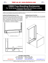
Place unit(s) into rough opening(s). Open the carrier access door
and open the front doors by lifting the latch handle on the left be-
hind the carrier access door. See illustration on page 1 for location
of carrier access door. Note the mounting hole locations and drill
pilot holes into the studs. Securely fasten to the support framing
with the screws provided. See illustration below. Install screws
into all holes provided in both right and left side vertical trim frame
members.
Caution: Do not deform, force or twist the frame to fit an incorrect
rough opening or against an irregular surface. Do not overtighten
the installation screws. If necessary, shim the small space be-
tween the stud and the vertical, extruded aluminum trim frame.
Test all master doors, patron doors, and parcel locker doors to
ensure that they open and swing freely without binding or sticking.
WIDTHS
Overall 16-3/8” 31-1/8”
Rough Opening 15-5/8” 30-3/8”
Stud Spacing 17-1/8” 31-7/8”
HEIGHTS OVERALL ROUGH OPENING
Maximum Height 56-3/4 56
15 Doors High 55 54-1/4”
14 Doors High 51-1/2” 50-3/4”
13 Doors High 48” 47-1/4”
12 Doors High 44-1/2” 43-3/4”
11 Doors High 41” 40-1/4”
10 Doors High 37-1/2” 36-3/4”
9 Doors High 34” 33-1/4”
8 Doors High 30-1/2” 29-3/4”
7 Doors High 27” 26-1/4”
6 Doors High 23-1/2” 22-3/4”
5 Doors High 20” 19-1/4”
4 Doors High 16-1/2” 15-3/4”
3 Doors High 13” 12-1/4”
FASTENING MAILBOX UNIT TO FRAMING
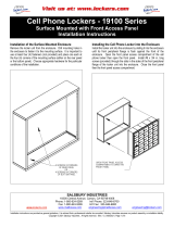
WALL FRAMING RECOMMENDATION
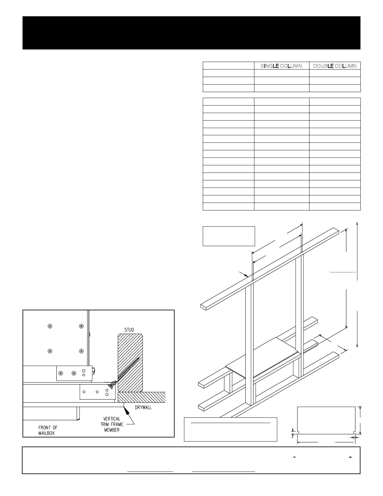
DIMENSIONS – FRONT LOADING
Page 6 of 6
#8 square
drive x 2”
long wood
screw
SINGLE COLUMN DOUBLE COLUMN
HEADER CONFIGURATION
SHOULD FOLLOW LOCAL
CODES, IF ANY. REMAINDER
OF WALL ABOVE HEADER
NOT SHOWN.
USE 3/8” PLYWOOD FOR PLATFORM.
CUT TWO NOTCHES TO FIT FRONT
2X4 STUDS. MAKE A PLATFORM FOR
EACH UNIT BEING INSTALLED.
PLATFORM
56” ROUGH
OPENING
FOR MAXIMUM
HEIGHT UNIT
SEE TABLE ON
PAGE 1 FOR
SMALLER UNITS
SEE USPS
HEIGHT
REQUIREMENTS
ON PAGE 1
17”
1-1/2”
15”
3/4”
31-7/8”
30 3/8”
ROUGH
OPENING
31 7/8”
STUD
SPACING
WIDTH DIMENSIONS ARE FOR
DOUBLE COLUMN UNITS.
SUBTRACT 14-3/4” FOR
SINGLE COLUMN UNITS.
IMPORTANT NOTE FOR MAXIMUM HEIGHT UNITS
THE BOTTOM EDGE OF THE ROUGH OPENING MUST
BE AT 14” ABOVE THE FINISHED FLOOR IN ORDER TO
COMPLY WITH THE USPS VERTICAL POSITION
REQUIREMENTS SHOWN ON PAGE 1.
Installation instructions are provided as general guidelines. It is advised that a professional installer be consulted. Salsbury Industries assumes
no product assembly or installation liability. Copyright © 2015 Salsbury Industries. All rights reserved. (Rev. 20, 02/10/2017)
SALSBURY INDUSTRIES
1010 East 62nd Street, Los Angeles, CA 90001-1598
Phone: 800-624-5269 Int’l Phone: 323-846-6700 Fax: 800-624-5299 Int’l Fax: 323-846-6800
www.mailboxes.com [email protected]
  • Page 1 1
  • Page 2 2
  • Page 3 3
  • Page 4 4
  • Page 5 5
  • Page 6 6

Salsbury Industries 3716D-20AFU Installation guide

Type
Installation guide

Ask a question and I''ll find the answer in the document

Finding information in a document is now easier with AI