Leviton 41OUM-1M User guide

Category
Measuring, testing & control
Type
User guide
MEASUREMENT A
CC
URA
C
Y
Real Power and Energy
IEC 62053-22 Class
0.2S, ANSI C12.20 0.2
%
Reactive Power and Energy
IEC 62053-23 Class
2, 2
%
C
urren
t
0.2%
(
+
0.005
%
per °C deviation from
25°C)
from 1% to 5% of range;
0.1%
(
+
0.005
%
per °C deviation from
25°C)
from 5% to 100% of range
Vo
l
t
age
0.1%
(
+
0.005
%
per °C deviation from
25°C)
from 90 VAC
L-N
to 600 VAC
L-L
Sample Rate
2520 samples per second; no blind
t
i
m
e
Data Update Rate
1 sec.
Type of
M
e
as
ure
m
e
nt
True RMS; one to three phase AC sys
t
e
m
INPUT VOLTAGE CHARACTERISTICS
Measured AC
V
ol
t
age
Minimum 90 V
(156
V
)
for stated accuracy;
UL Maximums: 600 V
(347
V
); CE
Maximum: 300 V
Metering Over-Range
+2
0
%
Impedance
2.5 MΩ / 5
M
Ω
L-N L-L
Frequency
Range
45 to 65 Hz
INPUT
CURRENT
CHARACTERISTICS
CT Scaling
Primary: Adjustable from 5 A to 32,000 A
Measurement Input Range
0 to 0.333
VAC
or 0 to 1.0
VAC
(
+
20
%
over-range),
rated for use
w
i
t
h
Class
1 voltage inpu
t
s
Impedance
10.6 kΩ
(1/3
V
mode)
or 32.1 kΩ
(1
V
m
ode
)
Series 4DUMR Bi-Directional, ModBus Meter
Series 41OUM Bi-Directional, ModBus in an Outdoor NEMA 4X
enclosure
Installation
Guide
Power
Monitoring
TM
RoHS
C
ompliant
DANGER
HAZARD
OF
ELEC
TRIC
SHOCK
,
EXPLOSION, OR
ARC
FLASH
F
ollo
w
safe
electric
al
w
ork
prac
tic
es
.
S
ee
NFPA
70E
in
the
USA,
or
applicable
loc
al
c
odes
.
T
his
equipmen
t
must
only
be
installed
and
ser
vic
ed
b
y
qualified
electric
al
personnel
.
Read
,
understand
and
f
ollo
w
the
instructions
bef
ore
installing
this
produc
t
.
T
urn
off
all
po
w
er
supplying
equipmen
t
bef
ore
w
ork
ing
on
or
inside
the
equipmen
t
.
An
y
c
o
v
ers
tha
t
ma
y
be
displaced
during
the
installation
must
be
r
einstalled
bef
ore
po
wering
the
unit
.
U
se
a
properly
ra
t
ed
v
oltage
sensing
de
vic
e
t
o
c
onfirm
po
w
er
is
o
.
DO NOT DEPEND
ON
THIS PRODUCT FOR VOLTAGE
INDIC
A
TION
Series 4100
B
i
-Dire
cti
onal Compact
ModBus Power and Energy M
e
t
er
Product O
v
er
vie
w
The E51 DIN
R
ai
l
Power
M
e
t
e
r
provides
a
s
o
l
u
t
i
o
n
f
o
r
m
ea
s
u
r
i
ng
e
n
e
r
g
y
data
with
a
single
device.
Inpu
t
s
i
n
c
l
ud
e
C
o
n
t
r
o
l
P
o
w
e
r
,
C
Ts
,
and 3-phase vo
l
t
a
g
e
.
The E51
s
upp
o
r
t
s
m
u
l
t
i
p
l
e
output
o
p
t
i
o
n
s
,
including
s
o
l
i
d
s
t
at
e
r
e
l
a
y
c
o
n
t
ac
t
s
,
Modbus
(
w
i
t
h
o
r
without
data logging), and
pu
l
s
e
.
The
L
CD
screen
o
n
t
h
e
faceplate
a
ll
o
w
s
i
n
s
t
an
t
o
u
t
pu
t
v
iewing
.
The E51
M
e
t
e
r
i
s
c
a
p
a
b
l
e
o
f
b
i
d
i
r
e
c
t
i
ona
l
m
e
t
e
r
i
ng.
Power
i
s
m
o
n
i
t
o
r
e
d
i
n
b
o
t
h
d
i
r
e
c
t
i
o
n
s
(
up
s
t
r
e
am
an
d
d
o
w
n
s
t
r
e
am
from
t
h
e
m
e
t
e
r)
.
The
m
e
t
e
r
i
s
housed
i
n
a
p
l
a
s
t
i
c
e
n
c
l
o
s
u
r
e
s
u
i
t
a
b
l
e
f
o
r
i
n
s
t
a
ll
at
i
o
n
o
n
T
35
DIN
r
ai
l
according
t
o
E
N
50022.
The E51 c
an
b
e
m
o
un
t
e
d
e
i
t
h
e
r
o
n
a
DIN
rail
o
r
i
n
a
p
an
e
l
.
Observe
c
o
rr
e
c
t
C
T
o
r
i
e
n
t
a
t
i
o
n
when
i
n
s
t
al
li
ng
t
he
d
e
v
ic
e
.
Product
I
dentification
Failure
to follow
these
instructions
will
result
in
death
or
serious
injur
y
.
A
qualified
person
is
one
who
has
skills and
kno
wledge
r
ela
t
ed
t
o
the
construction and
oper
a
tion
of
this
electrical equipmen
t
and
the
installation,
and
has
received saf
et
y
training
t
o
recognize
and
a
v
oid
the
hazards
involved.
NEC2009
Article 100
N
o
responsibility
is
assumed
by
Leviton
f
or
any consequences
arising
out
of
the
use
of
this
ma
t
erial.
C
on
tr
ol
syst
em
design
must
consider
the
potential failure
modes
of
control paths and,
f
or
certain critical control functions, pr
o
vide
a
means
t
o
achieve
a
safe
sta
t
e
during
and
af
t
er
a
pa
th
failure.
Examples
of
critical control functions
are
emer
gency
stop
and
ov
er-tr
av
el
stop.
WARNING
LOSS OF
C
ONTROL
Assure
tha
t
the
syst
em
will
reach a
safe
sta
t
e
during
and
af
t
er
a
control
pa
th
failur
e
.
S
epara
t
e
or
r
edundan
t
control paths
must
be
provided
f
or
critical control functions.
Test
the
eff
ec
t
of
transmission delays
or
failures
of
communication links.
1
E
ach
implemen
tation
of
equipmen
t
using
communication links
must
be
individually
and
thor
oughly
t
ested
f
or
proper operation before
placing
it
in
service
.
F
ailur
e
t
o
follow
these
instructions may
cause injury,
dea
th
or
equipmen
t
damage.
1
For
additional information about anticipa
t
ed
transmission delays or failures of the link, refer
t
o
NEMA ICS
1.1 (la
t
est
edition).
S
afet
y
Guidelines for
the
Application, Installation,
and
Maint
enanc
e
of
S
olid-
Sta
t
e
C
ontrol
or its equivalen
t
in your specific country, language, and/or loca
tion.
NO
TICE
This
product
is not
intended
for life or
safety applica
tions
.
Do not
install
this
product
in
hazardous
or
classified loca
tions
.
The
installer
is
responsible
for
conformance to
all
applicable
c
odes
.
Mount
this
product inside
a
suitable
re
and electrical enclosur
e
.
FCC PART
15 INFORMATION
NOTE: This
equipment
has been
t
ested by the manufacturer and found
t
o
comply with the limits for a
class B
digital device, pursuan
t
to part
15
of
the
FCC Rules. These
limits are designed
to
provide reasonable
pr
ot
ec
tion
against harmful
in
t
er
f
er
ence
when the
equipment
is oper
a
t
ed in a
residential en
vir
onmen
t
.
This
equipment
gener
a
t
es
,
uses,
and can
r
adia
t
e
radio frequency energy and, if not installed and used in accordance
with
the
instruction
manual, may
cause
harmful
in
t
er
f
er
ence
to r
adio
communications.
This
device complies with
part
15 of the
FCC
Rules.
Operation is subjec
t
to
the
following two
c
onditions:
(1) This
device may not
cause
harmful
in
t
er
f
er
ence
,
and
(2) this device must accept any
in
t
er
f
er
ence
received,
including
in
t
er
f
er
ence
that
may
cause
undesired oper
a
tion.
Modifications
to
this
product without
the
express
authorization
of
the
manufacturer nullify this sta
t
emen
t
.
F
o
r
u
s
e
i
n
a
P
o
ll
u
t
i
o
n
D
e
g
r
ee
2
o
r
b
e
tt
e
r
e
nv
i
r
o
n
m
e
n
t
only.
A
P
o
ll
u
t
i
o
n
D
e
g
r
ee
2
e
nv
i
r
onmen
t
m
us
t
c
on
t
r
o
l
c
ondu
c
t
i
v
e
pollution
a
nd
t
h
e
p
o
ss
i
bi
li
t
y
o
f
c
onden
s
a
t
i
on
or
h
i
gh
humidity.
C
o
n
s
i
d
e
r
t
h
e
e
n
c
l
o
s
u
r
e
,
t
h
e
c
o
rr
e
c
t
u
s
e
o
f
ventilation, thermal
p
r
o
p
e
r
t
i
e
s
o
f
t
h
e
e
qu
i
p
m
e
n
t
,
a
nd
t
h
e
r
e
l
a
t
i
o
n
s
h
i
p
w
i
t
h
t
h
e
e
nv
i
r
o
n
m
e
n
t
.
In
s
t
a
ll
a
t
i
o
n
c
a
t
e
g
o
r
y:
CAT
II
o
r
CAT III. P
r
o
v
i
d
e
a
d
i
s
c
o
nn
e
c
t
d
e
v
i
c
e
t
o
d
i
s
c
o
nn
e
c
t
t
h
e
m
e
t
e
r
f
r
o
m
t
h
e
s
upp
l
y
source.
P
l
a
c
e
t
h
i
s
d
e
v
i
c
e
i
n
c
l
o
s
e
proximity
t
o
t
h
e
e
qu
i
p
m
e
n
t
a
nd
w
i
t
h
i
n
ea
s
y
reach o
f
t
h
e
o
p
e
r
a
t
o
r
,
a
nd
m
a
r
k
i
t
a
s
t
h
e
d
i
s
c
o
nn
e
c
t
i
ng
device.
T
h
e
d
i
s
c
o
nn
e
c
t
i
ng
d
e
v
i
c
e
s
h
a
ll
m
ee
t
t
h
e
r
e
l
e
v
a
n
t
r
e
qu
i
r
e
m
e
n
t
s
o
f
I
EC
60947-1
a
nd
I
EC
60947-3
a
nd
s
h
a
ll
b
e
s
u
i
t
a
b
l
e
f
o
r
t
h
e
a
pp
li
c
a
t
i
o
n.
In
t
h
e
U
S
a
nd
C
a
n
a
d
a
,
d
i
s
c
o
nn
e
c
t
i
ng
f
u
s
e
h
o
l
d
e
r
s
c
a
n
b
e
used.
P
r
o
v
i
d
e
o
v
e
r
c
u
rr
e
n
t
p
r
o
t
e
c
t
i
o
n
a
nd
d
i
s
c
o
nn
e
c
t
i
ng
d
e
v
i
c
e
f
o
r
s
upp
l
y
c
o
ndu
c
t
o
r
s
w
i
t
h
a
pp
r
o
v
e
d
c
ur
r
e
n
t
limiting
devices
s
ui
t
a
b
l
e
f
o
r
p
r
o
t
e
c
t
ing
t
he
w
iring
.
If
t
he
e
q
uipm
e
n
t
i
s
u
s
e
d
in
a
m
a
nn
e
r
n
o
t
s
p
e
c
ifi
e
d
by
t
h
e
m
a
nu
f
a
c
t
u
r
e
r
,
t
h
e
p
r
o
t
e
c
t
i
o
n
provided by
t
h
e
d
e
v
i
c
e
m
a
y
b
e
im
p
a
ir
e
d.
S
pecifications
L-N
L-L
L-L
L-N
L-N
The VerifEye™ Series 4100 Bidirectional ModBus Meters feature bidirectional
monitoring specifically designed for renewable energy applications. The Series
4100 meters are revenue-grade (ANSI C12.20 Class 0.2%) kWh electrical
meters.
The Series 4100 meters are available in standalone DIN rail mount or NEMA 4X
enclosure. The 3-phase, advanced communication meters are compatible with
solid core, split core or flexible rope-style Rogowski current transformers.
Installation
G
uide
Power
M
onit
oring
Series 4100 Modbus
TM
2
AC
5 VA max.; 90V
m
in.;
UL Maximums: 600 V
L-L
(347 V
L-N
); CE
Maximum: 300 V
L-N
D
C*
3 W max.; UL and
CE:
125 to 300 VDC
Ride Through Ti
m
e
100 msec at 120 VAC
Alarm Contacts
N.C., static output
(
30
V
A
C
/ DC, 100mA max.
@
25°C,
derate 0.56mA per °C above 25°
C
)
Real Energy
Pulse
Contacts
N.O., static output
(30
V
A
C
/ DC, 100 mA max.
@
25°C,
derate 0.56 mA per °C above 25°
C
)
RS-485 Port
2
-
w
ire, 1200 to 38400 baud, Modbus RTU
W
eigh
t
0.62 lb
(0.28 kg)
IP Degree of Protection
(IEC
60529)
IP40 front display; IP20
M
e
t
er
Display Characteristics
Back-lit
blue LCD
Terminal
Block
Screw Torque
0.37 to 0.44
ft
-
lb
(0.5
to 0.6 N
·
m
)
Terminal
Block
Wire Size
24 to 14 AWG
(0.2
to 2.1
mm
2
)
Ra
il
T35
(35mm)
DIN
Rail
per EN50022
Operating Temperature Range
-30°
to 70°C
(
-22°
to 158°
F
)
Storage Temperature Range
-40°
to 85°C
(
-40°
to 185°
F
)
Humidity Range
<95% RH noncondensing
Altitude of Opera
ti
on
3000
m
US and Canada
CAT
III, Pollution degree 2;
for distribution systems up to 347V
L-N
/ 600VAC
L-L
CE
CAT
III, Pollution degree 2;
for distribution systems up to 300V
L-N
Dielectric
W
iths
t
and
Per UL 508, EN61010
Conducted and
Ra
dia
t
ed
E
mi
ss
ion
s
FCC
part 15
Class
B,
EN55011/EN61000 Class
B
(residential
and ligh
t
indus
tr
i
al
)
Conducted and
Ra
dia
t
ed
I
mm
uni
t
y
EN61000
Class
A
(heavy indus
t
ri
a
l
)
US and Canada (cULus)
UL508
(open
type
device)/CSA
22.2 No. 14
-
05
Europe (CE)
E
N61010
-
1
Specifications
(
con
t.)
SunSpec
A
lliance
I
n
t
eroper
ability
S
pecification
C
omplianc
e
*
External DC current limiting is required, see fuse recommendations.
T
h
i
s
m
e
t
e
r
i
m
p
l
e
m
e
n
t
s
t
h
e
draft
SunSpec
1.0
common
e
l
e
m
e
n
t
s
s
t
a
r
t
i
ng
at
b
a
s
e
1
address 40001, and
t
h
e
proposed SunSpec
1.1
m
e
t
e
r
model
at
40070
(
t
h
e
s
e
addresses
a
r
e
n
o
t
i
n
Modicon
n
o
t
at
i
o
n
)
.
The SunSpec
A
ll
ian
c
e
l
o
g
o
i
s
a
t
r
a
d
e
m
a
r
k
o
r
r
e
g
i
s
t
e
r
e
d
t
r
a
d
e
m
a
r
k
o
f
t
h
e
SunSpec
A
ll
ian
c
e
.
Installation
G
uide
Power
M
onit
oring
Series 4100 Modbus
TM
3
Table of
C
on
t
en
ts
Dimensions
4
A
pplic
a
tion
Example
4
Da
ta
O
utputs
5
P
r
oduc
t
Diagram
5
D
isplay
Screen
Diagram
5
Installation
6
S
uppor
t
ed
S
yst
em
Types
7
Wiring
S
ymbols
7
Wiring
8
C
on
tr
ol
P
o
w
er
Diagrams
9
Quick
S
etup
Instructions
10
S
olid
S
ta
t
e
Pulse
O
utput
11
U
ser
In
t
erfac
e
Menu
Abbreviations Defined
11
U
ser
In
t
erfac
e
f
or
Da
ta
C
onfigur
a
tion
12
Alert/Reset Information
13
U
ser
In
t
erfac
e
f
or
S
etup
15
RS-485
C
ommunic
a
tions
17
Da
ta
L
ogging
(E51C3
Only)
17
Modbus
P
oin
t
Map
Overview
18
S
tandard
Modbus
D
efault
S
ettings
19
Modbus
P
oin
t
Map
20
SunSpec
Register
Blocks
30
T
r
oubleshooting
34
C
hina
RoHS
C
omplianc
e
Information
(EFUP
Table)
34
Installation
G
uide
Power
M
onit
oring
Series 4100 Modbus
TM
4
Dimensions
1.8”
(45mm)
1.9”
(48mm)
2.3”
(59mm)
4.2”
(107mm)
1.5”
(39mm)
3.6”
(91mm)
Bottom
V
iew
(DIN
Mount
O
ption)
Bottom
V
iew
(Sc
r
ew
Mount
O
ption)
4.2
(107
mm)
2.4
(61
mm)
1.2
+
(31
mm)
+
0.3
(8
mm)
0.2
3.6
(91
mm)
3.9“
(99
mm)
4.3
(109
mm)
(4
mm)
0.4
+
(10
mm)
Application
E
x
ample
Main
Utility Grid
S
olar
P
anels
Imported
P
o
w
er
Expor
t
ed
P
o
w
er
Installation
G
uide
Power
M
onit
oring
Series 4100 Modbus
TM
5
VA
IA
VB
IB
VC
IC
N
eutr
al
Phase
Loss
A
larm
E
ar
th
P
ulse
C
on
tr
ol
Po
w
e
r
Modbus
Shield
Data O
utputs
Product Diagr
am
S
igned
Power: Real,
Reac
tiv
e
,
and
A
pparen
t
3-phase
t
otal
and
per
phase
Real
and
A
pparen
t
E
nergy
A
cc
umula
t
ors:
Import,
Expor
t
,
and
N
et;
3-phase
t
otal
and
per
phase
Reactive
E
nergy
A
cc
umula
t
ors
by Quadrant: 3-phase
t
otals
and
per
phase
C
onfigur
able
for
C
T
&
PT
ratios, system
t
ype,
and
passw
or
ds
Diagnostic alerts
C
urr
en
t:
3-phase
average
and
per
phase
Volts: 3-phase
average
and
per
phase
Line-Line and
Line-N
eutr
al
Power
F
ac
t
or:
3-phase
average
and
per
phase
F
r
equenc
y
Power Demand:
Most
Rec
en
t
and
P
eak
(Import
and
Expor
t)
Demand
C
onfigur
a
tion:
Fixed,
Rolling
Block,
and
Ex
t
ernal
Sync
(Modbus
only)
Da
ta
L
o
gging
Real
Time
C
lock:
user
c
onfigur
able
10
user
configurable
log
buffers:
each
buffer
holds
5760
16-bit
entries
(User
c
o
n
fi
gu
r
e
s
which
10
data
p
o
i
n
t
s
a
r
e
s
t
o
r
e
d
i
n
t
h
e
s
e
bu
ff
e
r
s
)
User
configurable
logging
in
t
erv
al
(
W
h
e
n
configured
f
o
r
a
15
minute
i
n
t
e
r
v
a
l
,
each buffer
h
o
l
d
s
60
days
o
f
dat
a
)
C
on
tinuous
and
S
ingle
Shot
logging
modes:
user
selec
table
Auto write pause: read
logs
without
disabling
the
met
er
s
da
ta
logging
mode
X2 X1 X2 X1 X2 X1
(X2)
A
(X1) (X2)
B
(X1) (X2)
C
(
X1)
Alarm
E
nergy
OUTPUT
CT
Inputs
1 or 0.333
VA
C
NC
NO
+
-
S
T
w
o
5-
char
ac
t
er
r
o
w
s
of
display
t
ex
t
.
T
op
r
o
w
alphanumer
ic;
Bottom
r
o
w
numer
ic
only
T
he
r
ed
Alar
m
LED
lights
when
+
Alarm
E
nergy
an
y
of
the
3
phase
voltages
dr
op
b
elo
w
the
selec
t
ed
thr
esh
-
old.
T
he
green
E
ner
g
y
LED
lights
VOLTAGE
INPUT
S
CAT
III 50/60
Hz
UL: 90V
L-N
- 600V
L-
L
CE:
90V
L-N
- 300V
L-
N
CONTROL POWER
0.1A 50/60
Hz
momentarily
each
time
the
E
ner
g
y
output
pulse
is
ac
tiv
e
.
A
B
C
N
1
2
Display
Scr
een
Diagr
am
Installation
G
uide
Power
M
onit
oring
Series 4100 Modbus
TM
6
Installation
D
i
sc
on
n
ec
t
power prior
t
o
i
n
s
t
a
ll
a
t
i
on
.
R
ei
n
s
t
a
ll
any covers
th
a
t
are
d
i
s
p
l
a
c
e
d
dur
i
ng
the
i
n
s
t
a
ll
a
t
i
on
before powering the un
i
t
.
Mount the meter
i
n
a
n
a
pp
r
o
p
r
i
a
t
e
e
l
ec
tr
i
c
a
l
en
c
lo
s
ur
e
near
equipment
t
o
be mon
i
t
or
e
d
.
Do
n
o
t
i
n
s
t
a
ll
on
the load
s
ide
o
f
a
Variable
F
re
qu
en
c
y
Drive (VFD), aka Variable Speed Drive
(
V
S
D
)
or
A
dj
us
t
a
b
l
e
F
re
qu
en
c
y
Drive
(
AF
D
)
.
O
b
s
er
v
e
c
or
r
ec
t
C
T
or
i
en
t
a
t
i
on
.
The
m
e
t
e
r
c
an
b
e
m
o
un
t
e
d
i
n
t
w
o
ways: o
n
s
t
anda
r
d
35
mm
DIN
rail
o
r
s
c
r
e
w-
m
o
un
t
e
d
t
o
t
h
e
interior
s
u
r
f
ac
e
o
f
t
h
e
e
n
c
l
o
s
u
r
e
.
A.
D
I
N
R
a
il
Mo
un
t
i
n
g
1. A
tt
ac
h
t
h
e
mounting
c
l
i
p
s
t
o
t
h
e
underside o
f
t
h
e
housing
b
y
s
l
i
d
i
ng
them
i
n
t
o
t
h
e
s
l
o
t
s
from
t
h
e
i
n
si
d
e
.
The
s
t
o
pp
i
ng
p
e
g
s
m
u
s
t
face
t
h
e
housing, and
t
h
e
o
u
t
si
d
e
e
dg
e
o
f
t
h
e
c
l
i
p
m
u
s
t
b
e
flush
with
t
h
e
o
u
t
si
d
e
e
dg
e
o
f
t
h
e
h
o
u
si
ng.
2.
S
na
p
t
h
e
c
l
i
p
s
o
n
t
o
t
h
e
DIN
rail.
S
ee
t
h
e
diagram o
f
t
h
e
underside o
f
t
h
e
housing
(b
e
l
o
w
)
.
C
lip
flush
with
outside
edge
Inser
t
clips
fr
om
inside
S
nap
ont
o
DIN
r
ail
3.
T
o
reduce
h
o
r
i
z
o
n
t
a
l
shifting
across
t
h
e
DIN
rail,
use
t
w
o
e
nd
s
t
o
p
c
l
i
p
s
.
B.
S
c
r
e
w
Mo
un
t
i
n
g
1. A
tt
ac
h
t
h
e
mounting
c
l
i
p
s
t
o
t
h
e
underside o
f
t
h
e
housing
b
y
s
l
i
d
i
ng
them
i
n
t
o
t
h
e
s
l
o
t
s
from
t
h
e
o
u
t
si
d
e
.
The
s
t
o
pp
i
ng
p
e
g
s
m
u
s
t
face
t
h
e
housing, and
t
h
e
screw
hole
m
u
s
t
b
e
exposed
o
n
t
h
e
o
u
t
si
d
e
o
f
t
h
e
h
o
u
si
ng.
2.
U
s
e
t
h
r
ee
#8
screws
(
n
o
t
s
upp
l
i
e
d
)
t
o
mount
t
h
e
m
e
t
e
r
t
o
t
h
e
inside o
f
t
h
e
e
n
c
l
o
s
u
r
e
.
S
ee
t
h
e
diagram o
f
t
h
e
underside o
f
t
h
e
ho
u
s
ing
(
bel
o
w
)
.
Inser
t
clips
fr
om
outside
S
c
r
ew
holes
exposed
f
or
mounting
Installation
G
uide
Power
M
onit
oring
Series 4100 Modbus
TM
7
Supported
S
y
s
t
em
T
ype
s
The
m
e
t
e
r
ha
s
a
number
o
f
different
p
o
s
si
b
l
e
s
y
s
t
e
m
wiring
c
o
n
fi
gu
rat
i
o
n
s
(see
Wiring Diagrams
s
e
c
t
i
o
n
)
.
T
o
configure
t
h
e
m
e
t
e
r
,
s
e
t
t
h
e
S
y
s
t
e
m
Type via
t
h
e
U
s
e
r
In
t
e
r
f
ac
e
o
r
Modbus
r
e
g
i
s
t
e
r
130
(
if
s
o
equipped).
The
S
y
s
t
e
m
Type
t
e
ll
s
t
h
e
m
e
t
e
r
which
o
f
i
t
s
c
u
rr
e
n
t
and vo
l
t
a
g
e
i
npu
t
s
a
r
e
valid, which
a
r
e
t
o
b
e
ignored, and
if
n
e
u
t
r
a
l
i
s
c
o
nn
e
c
t
e
d
.
S
e
tt
i
ng
t
h
e
c
o
rr
e
c
t
S
y
s
t
e
m
Type
p
r
e
v
e
n
t
s
un
w
an
t
e
d
e
n
e
r
g
y
accumulation o
n
unused
i
npu
t
s
,
s
e
l
e
c
t
s
t
h
e
formula
t
o
c
a
lc
u
l
at
e
t
h
e
T
h
e
o
r
e
t
i
c
a
l
Maximum
S
y
s
t
e
m
P
o
w
e
r
,
and
d
e
t
e
rm
i
n
e
s
which phase
l
o
ss
algorithm
i
s
t
o
b
e
used. The phase
l
o
ss
algorithm
i
s
configured
a
s
a
p
e
r
c
e
n
t
o
f
t
h
e
L
i
n
e
-
t
o
-
L
i
n
e
S
y
s
t
e
m
V
o
l
t
a
g
e
(
e
x
c
e
p
t
w
h
e
n
i
n
S
y
s
t
e
m
Type
10
)
and
a
l
s
o
c
a
lc
u
l
at
e
s
t
h
e
e
x
p
e
c
t
e
d
L
i
n
e
t
o
N
e
u
t
r
a
l
vo
l
t
a
g
e
s
f
o
r
s
y
s
t
e
m
t
y
p
e
s
t
hat
have
N
e
u
t
r
a
l
(12
&
40
)
.
V
a
l
u
e
s
t
hat
a
r
e
n
o
t
valid
i
n
a
p
a
r
t
i
c
u
l
a
r
S
y
s
t
e
m
Type
w
i
ll
display
a
s
----
o
n
t
h
e
U
s
e
r
In
t
e
r
f
ac
e
o
r
a
s
Q
N
A
N
i
n
t
h
e
Modbus
r
e
g
i
s
t
e
r
s
.
C
Ts
Voltage
C
onnec
tions
S
ystem
T
ype
Phase
Loss
Measur
emen
ts
W
iring
D
iagram
Number
of
wir
es
Qt
y
ID
Qt
y
ID
T
ype
Modbus
Register
130
U
ser
In
t
erfac
e:
SETUP>S
SY
S
VLL
VLN
B
alanc
e
D
iagram
number
S
ingle
-Phase
W
iring
2
1
A
2
A,
N
L-
N
10
1L
+
1n
AN
1
2
1
A
2
A,
B
L-
L
11
2L
AB
2
3
2
A,
B
3
A,
B
,
N
L
-L
with
N
12
2L
+
1n
AB
AN,
BN
AN-BN
3
Three-Phase
W
iring
3
3
A,
B
,
C
3
A,
B
,
C
D
elta
31
3L
AB
,
BC,
C
A
AB-BC-
C
A
4
4
3
A,
B
,
C
4
A,
B
,
C,
N
G
r
ounded
Wy
e
40
3L
+
1n
AB
,
BC,
C
A
AN,
BN,
CN
AN-BN-CN
&
AB-BC-
C
A
5,
6
Wiring
S
ymbols
T
o
avoid
d
i
s
t
o
r
t
i
o
n
,
use
parallel
w
i
r
e
s
f
o
r
c
o
n
t
r
o
l
power and vo
l
t
a
g
e
i
npu
t
s
.
The
following
s
y
m
b
o
l
s
a
r
e
used
i
n
t
h
e
wiring
d
ia
g
r
am
s
o
n
t
h
e
following
p
a
g
e
s
.
S
ymbol
D
escription
V
oltage
Disc
onnec
t
S
wit
ch
F
use
(installer
is
responsible
f
or
ensuring
c
omplianc
e
with
loc
al
r
equiremen
ts.
N
o
fuses
ar
e
included
with
the
met
er
.)
E
ar
th
ground
X1
X2
C
urr
en
t
T
r
ansduc
er
P
ot
en
tial
T
r
ansf
ormer
Protection containing
a
voltage
disc
onnec
t
switch
with
a
fuse
or
disc
onnec
t
cir
c
uit
br
eaker.
T
he
protection
devic
e
must
be
r
a
t
ed
f
or
the
available shor
t-
cir
c
uit
c
urr
en
t
a
t
the
connection
poin
t
.
C
A
UTION
RISK OF EQUIPMENT
DAM
A
GE
This
product
is
designed
only for use with
1V
or
0.33V
curr
en
t
transducers
(CTs).
DO NOT USE CURRENT OUTPUT
(e.g.
5A) CTs ON THIS PRODUC
T
.
Failure to follow these
instructions
can result in
overheating
and
permanent equipment
damage
.
Installation
G
uide
Power
M
onit
oring
Series 4100 Modbus
TM
8
B
W
iring
W
ARNING
RISK
OF
ELECTRIC SHOCK
OR
PERMANENT
EQUIPMENT
DAMA
GE
C
T
negative
t
erminals
are referenced
t
o
the
met
er
s
neutral
and
may be
a
t
elev
a
t
ed
voltages
· Do
not
c
ontac
t
met
er
t
erminals
while
the
unit
is
c
onnec
t
ed
· Do
not
c
onnec
t
or
shor
t
other
circuits
t
o
the
C
T
t
erminals
Failure
to
f
ollo
w
these
instructions
ma
y
cause injury, death
or
equipment
damage
.
O
b
s
er
v
e
c
or
r
ec
t
C
T
or
i
en
t
a
t
i
on
.
D
iagr
am
1:
1-Pha
se
Line
-t
o-N
eutr
al
2-
W
ir
e
S
ystem
1
C
T
U
s
e
S
y
s
t
e
m
T
yp
e
10
(
1
L
+
1
n
)
N L1
D
iagr
am
2:
1-Pha
se
Line
-t
o-Line
2-
W
ir
e
S
ystem
1
C
T
U
s
e
S
y
s
t
e
m
T
yp
e
11
(
2
L
)
L1 L2
A
B
C
N
X1
White
X1
A
B
C
N
W
hit
e
B
lack
X2
X1
A
X2
X2
X1
X2
B
X1
X2
C
X1
Black
X2
A
X1
X2
B
X1
X2
C
D
iagr
am
3:
1-Pha
se
D
ir
ec
t
V
oltage
C
onnec
tion
2
C
T
D
iagr
am
4:
3-Pha
se
3-
W
ir
e
3
C
T
no
P
T
N L1 L2
U
s
e
S
y
s
t
e
m
T
yp
e
12
(
2
L
+
1
n
)
L1 L2 L3
U
s
e
S
y
s
t
e
m
Type
31
(
3
L
)
X1
X2
X1
X2
W
hit
e
B
lack
W
hit
e
B
lack
A
B
C
N
X1
X2
A
X1
X2
X1
X2
C
X1
X2
X1
X2
X1
X2
W
hit
e
B
lack
W
hit
e
B
lack
W
hit
e
B
lack
A
B
C
N
X1
X2
A
X1
X2
B
X1
X2
C
D
iagr
am
5:
3-Pha
se
4-
W
ir
e
Wy
e
D
ir
ec
t
V
oltage
Input
C
onnec
tion
3
C
T
U
s
e
S
y
s
t
e
m
Type
40
(
3
L
+
1
n
)
D
iagr
am
6:
3-Pha
se
4-
W
ir
e
Wy
e
C
onnec
tion
3
C
T
3
PT
U
s
e
S
y
s
t
e
m
T
yp
e
40
(
3
L
+
1
n
)
N
L1
L2 L3
N
L1
L2 L3
X1
X2 X1
X2 X1
X2
W
hit
e
B
lack
W
hit
e
B
lack
W
hit
e
B
lack
A
B
C
N
X1
X2
A
X1
X2
B
X1
X2
C
X1
X2
X1
X2
X1
X2
W
hit
e
B
lack
W
hit
e
B
lack
W
hit
e
B
lack
A
B
C
N
X1
A
X2
X1
B
X2
X1
C
X2
Installation
G
uide
Power
M
onit
oring
Series 4100 Modbus
TM
9
Control
P
ow
er
D
ir
ec
t
C
onnec
t
C
ontr
ol
P
o
w
er
(Line
t
o
Line)
D
ir
ec
t
C
onnec
t
C
ontr
ol
P
o
w
er
(Line
t
o
N
eutr
al)
L1 L2 L3
G
1 2
N L1 L2 L3
G
1 2
L
i
n
e
t
o
Line
f
r
o
m
90
VA
C
t
o
600
VA
C
(
U
L
)
.
I
n
U
L
i
n
s
t
a
ll
a
t
i
o
n
s
t
h
e
li
n
e
s
m
ay
b
e
fl
o
a
t
i
n
g
(
s
u
c
h
a
s
a
d
e
l
t
a
)
.
I
f
a
n
y
li
n
e
s
a
r
e
t
i
e
d
t
o
a
n
e
a
r
t
h
(
s
u
c
h
a
s
a
c
o
r
n
e
r
grounded d
e
l
t
a
)
,
s
ee
t
h
e
L
i
n
e
t
o
N
e
u
t
r
a
l
installation
l
imi
t
s
.
In
C
E
c
o
m
p
li
a
n
t
in
sta
ll
at
ion
s
,
t
h
e
l
in
es
mu
st
b
e
neutral (earth)
r
e
f
e
r
e
n
c
e
d
a
t
l
e
ss
t
h
a
n
300
VA
C
L-
N
D
ir
ec
t
C
onnec
t
C
ontr
ol
P
o
w
er
(DC
C
ontr
ol
P
o
w
er)
L
i
n
e
t
o
N
e
u
t
r
a
l
f
r
o
m
90
VA
C
t
o
347
VA
C
(
U
L
)
o
r
300
VA
C
(
C
E
)
C
ontr
ol
P
o
w
er
T
r
ansf
or
mer
(
CP
T
)
C
onnec
tion
G
1 2
N L1 L2 L3
G
1 2
D
C
C
o
n
t
r
o
l
P
o
w
e
r
f
r
o
m
125
V
D
C
t
o
300
V
D
C
(
U
L
a
n
d
C
E
m
a
x
.
)
F
u
s
e
R
e
c
omm
e
n
d
a
t
i
on
s
T
h
e
C
o
n
t
r
o
l
P
o
w
e
r
Transformer
m
ay
b
e
wi
r
e
d
L
-
N
o
r
L
-
L
.
O
u
t
p
u
t
t
o
m
ee
t
m
e
t
er
in
p
u
t
r
e
qu
ir
em
en
t
s
K
ee
p
t
h
e
f
u
s
e
s
c
l
o
s
e
t
o
t
h
e
power source (obey
local and national
c
o
d
e
r
e
qu
i
r
e
m
e
n
t
s
)
.
F
o
r
s
e
l
e
c
t
i
ng
f
u
s
e
s
and
c
i
r
c
u
i
t
breakers, use
t
h
e
following
c
r
i
t
e
r
ia:
S
e
l
e
c
t
c
u
rr
e
n
t
interrupt
c
a
p
ac
i
t
y
based
o
n
t
h
e
i
n
s
t
a
ll
at
i
o
n
category and
fault
c
u
rr
e
n
t
c
a
p
a
b
i
l
i
t
y.
S
e
l
e
c
t
ov
e
r
-
c
u
rr
e
n
t
p
r
o
t
e
c
t
i
o
n
with
a
t
i
m
e
d
e
l
a
y.
S
e
l
e
c
t
a
vo
l
t
a
g
e
rating
s
u
ffi
c
i
e
n
t
f
o
r
t
h
e
i
npu
t
vo
l
t
a
g
e
a
pp
l
i
e
d
.
P
r
ov
i
d
e
ov
e
r
c
u
rr
e
n
t
p
r
o
t
e
c
t
i
o
n
and
d
i
s
c
o
nn
e
c
t
i
ng
means
t
o
p
r
o
t
e
c
t
t
h
e
w
i
r
i
ng.
F
o
r
A
C
i
n
s
t
a
ll
at
i
o
n
s
,
use Leviton CTV00-
FK3, or equivalent.
F
o
r
D
C
i
n
s
t
a
ll
at
i
o
n
s
,
provide
e
x
t
e
r
na
l
c
i
r
c
u
i
t
p
r
o
t
e
c
t
i
o
n.
S
ugg
e
s
t
e
d
:
0.5
A
,
t
i
m
e
d
e
l
a
y
f
u
s
e
s
.
The
ea
r
t
h
c
o
nn
e
c
t
i
o
n
(
G
)
i
s
required
f
o
r
e
l
e
c
t
r
o
m
a
gn
e
t
i
c
c
o
m
p
at
i
b
i
l
i
t
y
(
E
M
C
)
and
i
s
n
o
t
a
p
r
o
t
e
c
t
i
v
e
ea
r
t
h
g
r
o
und
.
Installation
G
uide
Power
M
onit
oring
Series 4100 Modbus
TM
10
Quick
Se
tup
I
ns
tructions
These
i
n
s
t
r
u
c
t
i
o
n
s
a
ss
u
m
e
t
h
e
m
e
t
e
r
i
s
s
e
t
t
o
f
ac
t
o
r
y
d
e
f
a
u
l
t
s
.
I
f
i
t
ha
s
been
p
r
e
v
i
o
u
s
l
y
configured,
check a
ll
o
p
t
i
ona
l
v
a
l
u
e
s
.
1. Press
the
+
+
or
button
repeatedly
until
SETUP
screen a
pp
ea
r
s
.
2.
t
o
t
h
e
PASWD
s
c
r
ee
n.
3.
through
t
he
d
i
gi
t
s.
U
s
e
the
+
+
or
bu
tt
o
n
s
t
o
s
e
l
e
c
t
t
h
e
password
(
t
h
e
d
e
f
a
u
l
t
i
s
00000).
E
x
i
t
t
h
e
screen
t
o
t
h
e
r
i
gh
t
.
4.
U
s
e
the
+
+
or
bu
tt
o
n
s
t
o
s
e
l
e
c
t
t
h
e
p
a
r
am
e
t
e
r
t
o
c
o
n
fi
gu
r
e
.
5.
I
f
t
h
e
un
i
t
ha
s
an
R
S
-
485
i
n
t
e
r
f
ac
e
,
t
h
e
fi
r
s
t
S
e
t
up
screen
i
s
S
COM
(
s
e
t
c
o
mm
un
i
c
at
i
o
n
s
)
.
a.
t
o
t
h
e
ADDR
screen and
t
h
r
o
ugh
t
h
e
address
d
i
g
i
t
s
.
U
s
e
the
+
+
or
bu
tt
on
s
t
o
s
e
l
e
c
t
t
he
Modbus
a
ddr
e
s
s.
b.
t
o
t
h
e
BAUD
screen.
U
s
e
the
+
+
or
bu
tt
o
n
s
t
o
s
e
l
e
c
t
t
h
e
baud
rat
e
.
c.
t
o
t
h
e
PAR
screen.
U
s
e
the
+
+
or
bu
tt
o
n
s
t
o
s
e
l
e
c
t
t
h
e
p
a
r
i
t
y.
d.
b
ac
k
t
o
t
h
e
S
COM
s
c
r
ee
n.
6.
t
o
t
h
e
S
CT
(
S
e
t
C
u
rr
e
n
t
Transducer) screen.
I
f
t
h
i
s
un
i
t
does
n
o
t
have
an
R
S
-
485
port,
t
h
i
s
w
i
ll
b
e
t
h
e
fi
r
s
t
s
c
r
ee
n.
a.
t
o
t
h
e
CT
V
screen.
U
s
e
the
+
+
or
bu
tt
o
n
s
t
o
s
e
l
e
c
t
t
h
e
vo
l
t
a
g
e
m
o
d
e
C
u
rr
e
n
t
T
r
an
s
du
c
e
r
output
vo
l
t
a
g
e
.
b.
t
o
t
h
e
CT
SZ
screen and
t
h
r
o
ugh
t
h
e
d
i
g
i
t
s
.
U
s
e
the
+
+
or
bu
tt
o
n
s
t
o
s
e
l
e
c
t
t
h
e
C
T
si
z
e
i
n
am
p
s
.
c.
b
ac
k
t
o
t
h
e
S
CT
s
c
r
ee
n.
7.
t
o
t
h
e
S
SYS
(
S
e
t
S
y
s
t
e
m)
s
c
r
ee
n.
a.
t
o
t
h
e
S
Y
ST
M
screen.
U
s
e
the
+
+
or
bu
tt
o
n
s
t
o
s
e
l
e
c
t
t
h
e
S
y
s
t
e
m
Type (see
wiring
d
ia
g
r
am
s
)
.
b.
b
ac
k
t
o
t
h
e
S
SYS
s
c
r
ee
n.
8.
(
O
p
t
i
ona
l
)
t
o
t
h
e
S
PT
(
S
e
t
P
o
t
e
n
t
ia
l
Transformer)
screen.
I
f
PTs
a
r
e
n
o
t
used,
t
h
e
n
skip
t
h
i
s
s
t
e
p
.
a.
t
o
t
h
e
R
A
TI
O
screen and
t
h
r
o
ugh
t
h
e
d
i
g
i
t
s
.
U
s
e
the
+
+
or
bu
tt
o
n
s
t
o
s
e
l
e
c
t
t
h
e
P
o
t
e
n
t
ia
l
Transformer
s
t
e
p
d
o
w
n
r
a
t
i
o.
b.
b
ac
k
t
o
t
h
e
S
PT
s
c
r
ee
n.
9.
t
o
t
h
e
S
V
(
S
e
t
S
y
s
t
e
m
V
o
l
t
a
g
e
)
s
c
r
ee
n.
a.
t
o
t
h
e
VLL
(or
VLN
if
s
y
s
t
e
m
i
s
1
L
-
1
n
)
screen and
t
h
r
o
ugh
t
h
e
d
i
g
i
t
s
.
U
s
e
the
+
+
or
bu
tt
o
n
s
t
o
s
e
l
e
c
t
t
h
e
L
i
n
e
t
o
L
i
n
e
S
y
s
t
e
m
V
o
l
t
a
g
e
.
b.
b
ac
k
t
o
t
h
e
S
V
s
c
r
ee
n.
10.
U
s
e
the
t
o
e
x
i
t
t
h
e
s
e
t
up
screen and
t
h
e
n
S
ET
U
P
.
11.
C
h
e
c
k
t
hat
t
h
e
wrench
i
s
n
o
t
d
i
sp
l
a
y
e
d
o
n
t
h
e
L
CD
.
a.
I
f
t
h
e
wrench
i
s
d
i
sp
l
a
y
e
d
,
use
the
+
+
or
bu
tt
o
n
s
t
o
fi
nd
t
h
e
ALERT
s
c
r
ee
n.
b.
t
h
r
o
ugh
t
h
e
screens
t
o
see
which
a
l
e
r
t
i
s
o
n.
F
o
r
t
h
e
full
s
e
t
up
i
n
s
t
r
u
c
t
i
o
n
s
,
see
t
h
e
configuration
i
n
s
t
r
u
c
t
i
o
n
s
o
n
t
h
e
following
p
a
g
e
s
.
Installation
G
uide
Power
M
onit
oring
Series 4100 Modbus
TM
11
Main
Menu
IEC
IEEE
D
escription
D
D
D
emand
MAX
M
Maximum
D
emand
P
W
P
r
esen
t
Real
P
o
w
er
Q
VA
R
P
r
esen
t
Reac
tiv
e
P
o
w
er
S
VA
P
r
esen
t
A
ppar
en
t
P
o
w
er
A
A
A
mps
UAB
,
UBC,
U
A
C
VAB
,
VBC,
V
A
C
V
oltage
Line
t
o
Line
V
VLN
V
oltage
Line
t
o
N
eutr
al
PF
PF
Power
F
ac
t
or
U
VLL
V
oltage
Line
t
o
Line
HZ
HZ
F
r
equency
KSh
K
VA
h
A
cc
umula
t
ed
A
ppar
en
t
E
nergy
KQ
h
K
VA
R
h
A
cc
umula
t
ed
Reactive
E
nergy
KPh
K
Wh
A
cc
umula
t
ed
Real
E
nergy
PL
OSS
PL
OSS
Phase
Loss
L
O
WPF
L
O
WPF
L
o
w
Power
F
ac
t
or
E
rr
or
F
ERR
F
ERR
Frequency
E
rr
or
I
O
VR
I
O
VR
O
ver
C
urr
en
t
V
O
VR
V
O
VR
O
ver
V
oltage
Main
Menu
IEC
IEEE
D
escription
PULSE
PULSE
kWh Pulse
O
utput
O
v
errun
(configuration error)
_PHASE
_PHASE
S
ummar
y
Da
ta
f
or
1,
2,
or
3
ac
tiv
e
phases
ALER
T
ALER
T
Diagnostic
A
ler
t
S
ta
tus
INFO
INFO
Unit
Inf
orma
tion
MODEL
MODEL
Model
Number
OS
OS
O
per
a
ting
S
yst
em
RS
RS
Reset
S
yst
em
SN
SN
S
erial
Number
RESET
RESET
Reset
Da
ta
P
ASWD
P
ASWD
E
n
t
er
Reset
or
S
etup
P
assw
ord
ENERG
ENERG
Reset
E
nergy
A
cc
umula
t
ors
DEMND
DEMND
Reset
Demand
Maximums
Impor
t
Expor
t
PULS_
PULS_
Pulse
C
oun
t
er
(if
equipped)
Q_
Q_
Q
uadr
an
t
1-4
per
IEEE
1459
n
n
Ne
t
Solid-Stat
e
Pulse O
utput
The
m
e
t
e
r
ha
s
one
normally
o
p
e
n
(N.O.)
KZ
F
o
rm
A
output
and one
normally
c
l
o
s
e
d
(
N.
C
.
)
K
Y
s
o
l
i
d
-
s
t
at
e
o
u
t
pu
t
.
O
n
e
i
s
dedicated
t
o
i
m
p
o
r
t
e
n
e
r
g
y
(Wh), and
t
h
e
o
t
h
e
r
t
o
A
l
a
rm
.
The
relay
used
f
o
r
t
h
e
Phase
Lo
ss
c
o
n
t
ac
t
i
s
N.
C
.,
with
c
l
o
s
u
r
e
indicating
t
h
e
p
r
e
s
e
n
c
e
o
f
an
a
l
a
rm
;
e
i
t
h
e
r
l
o
ss
o
f
phase
if
t
h
e
m
e
t
e
r
i
s
powered, o
r
l
o
ss
o
f
power
if
t
h
e
m
e
t
e
r
i
s
n
o
t
.
The
c
o
n
t
ac
t
s
a
r
e
o
p
e
n
w
h
e
n
t
h
e
m
e
t
e
r
i
s
powered and
n
o
p
ha
s
e
O
v
e
r
-
C
u
rr
e
nt
P
r
o
t
ec
t
i
v
e
De
v
ic
e
*
(
n
ot
s
u
pplied
)
100
mA
~
=
100
mA
Po
w
e
r
S
o
u
r
c
e
**
3-
30
V
D
C
6
-3
0
VA
C
Po
w
e
r
S
o
u
r
c
e
**
l
o
ss
a
l
a
rm
c
o
nd
i
t
i
o
n
s
a
r
e
p
r
e
s
e
n
t
.
The
s
o
l
i
d
s
t
at
e
pu
l
s
e
o
u
t
pu
t
s
a
r
e
rat
e
d
f
o
r
30
VAC/DC
n
o
m
.
+
S
Alarm
Energy
O
utput
~
=
3-
30
V
D
C
6
-3
0
VA
C
Maximum
l
o
a
d
c
u
rr
e
n
t
i
s
100
m
A
at
25°
C
.
D
e
rat
e
0.56
m
A
per
°C above
25°
C
.
S
ee
t
h
e
S
e
t
up
s
e
c
t
i
o
n
f
o
r
c
o
n
fi
gu
rat
i
o
n
inf
o
rm
a
t
ion
.
*
The
o
v
e
r
-
c
u
r
re
n
t
p
r
o
t
e
c
t
i
v
e
device
mu
s
t
b
e
rated
f
o
r
the
s
h
o
r
t
c
i
r
c
u
i
t
c
u
r
re
n
t
at
t
h
e
c
on
n
e
c
t
i
on
p
oin
t
.
**
All pulse o
u
t
p
u
t
s
and
c
o
mmun
i
c
a
t
i
o
n
c
i
r
c
u
i
t
s
are only intended to b
e
c
o
nn
e
c
t
e
d
t
o
n
o
n
-
h
a
z
a
r
d
o
u
s
c
i
r
c
u
i
t
s
(
SE
L
V
or
C
l
a
ss
2). Do
not
c
o
nn
e
c
t
to
hazardous v
o
l
t
ag
e
s
.
User Interface
(UI)
Menu
A
bbr
eviations
D
e
fined
The user
c
an
s
e
t
t
h
e
display
m
o
d
e
to
e
i
t
h
e
r
I
EC
o
r
I
EEE
notation
i
n
t
h
e
SETUP
m
e
nu
.
Installation
G
uide
Power
M
onit
oring
Series 4100 Modbus
TM
User
I
n
t
er
f
ac
e
To:
SETUP
IEEE Display Mode
Demand
DEMND
D KW DKVAR
D KVA
M KW
MKVAR
M KVA
M KW
MKVAR
M KVA
Present
Present
Present
Maximum Real
Maximum Reactive
Maximum Apparent
Maximum Real
Maximum Reactive
Maximum Apparent
Real
Power
Demand
(P)
Reactive Power
Demand (Q)
Apparent Power
Demand (S)
Power (P)
Import Demand
Power (Q)
Import Demand
Power (S)
Import Demand
Power (P)
Export Demand
Power (Q)
Export Demand
Power (S)
Export Demand
DEMND
Phase C:
3 Phase
Systems Only
CPHAS
C A C VAC
C VLN
C KW
CKVAR
C KVA
C PF
C +KWh
C -KWh
CPHAS
Phase B:
2 & 3 Phase BPHAS
Systems Only
B A B VBC
B VLN
B KW
BKVAR
B KVA
B PF
B +KWh
B -KWh
BPHAS
Phase A:
All Systems
APHAS
A A A VAB
A VLN
A KW
AKVAR
A KVA
A PF
A +KWh
A -KWh
APHAS
1, 2, or 3 Phase
Summary Data
_PHAS
3 A 3 VLL
3 VLN
3 KW
3KVAR
3 KVA
3 PF
3 +KWh
3 -KWh HZ
Amps
(A)
Volts Line-Line (U) Volts Line-Neutral (V)
Total Real
Total Reactive Total Apparent
Power Factor
Total Import
Total Export
Frequency
_PHAS
(Average
of
Active
Phases)
(Average of
Active
Phases)
(Average of
Active
Phases)
Power (P)
Power (Q) Power (S)
(Average of
Active Phases)
Real Energy Real Energy
>>> Scroll When Idle >>>
Energy
Accumulators
ENRGY
3 KWh
3 +KWh
3 -KWh
KVAR1
KVAR2 KVAR3
KVAR4
KVAh
KVAh
KVAh
PULS1
PULS2
and Counters
Signed Net
Import
Export
Quadrant 1 Quadrant 2 Quadrant 3 Quadrant 4
Signed Net
Import
Export
Pulse Counter 1
Pulse Counter 2
Real
Energy
Real Energy
Real Energy
Import Reactive Import Reactive Export Reactive Export Reactive
Apparent Energy
Apparent Energy
Apparent Energy
(Import Wh)
(Export Wh)
Energy
Energy Energy
Energy
See SETUP > SPULS > Wh/P
for Pulse
Value
ENRGY
To:
ALERT
T
he
units
for
all
Power
and
E
nergy
screens
change
t
o
preserve
r
esolution
as
the
ac
c
umula
t
ed
t
otals
increase. For
e
xample,
energy starts
out
as
Wh,
then
swit
ches
t
o
kWh,
M
W
h,
and
ev
en
tually
GW
h
as
the
ac
c
umula
t
ed
value incr
eases
.
12
Installation
G
uide
Power
M
onit
oring
Series 4100 Modbus
TM
User
I
n
t
er
f
ac
e
(
con
t.)
To:
SETUP
IEC Display Mode
Demand
DEMND
D KP D KQ
D KS
M KP
M KQ
M KS
M KP
M KQ
M KS
P
resen
t
Present
Present
Maximum Real
Maximum Reactive
Maximum Apparent
Maximum Real
Maximum Reactive
Maximum Apparent
Real
P
ower
Demand
Reactive
P
ower
Demand
Apparent Power
Demand
Power
I
mpor
t
Demand
P
ower
Import Demand
P
ower
Import Demand
Power
E
xpor
t
Demand
Power (Q)
Export Demand
Power (S)
Export Demand
DEMND
Phase C:
3 Phase
Systems Only
CPHAS
C A C U C V
Volts CA
C KP
C KQ
C KS
C PF
C +KPh
C -KPh
CPHAS
Phase B:
2 & 3 Phase BPHAS
Systems Only
B A B U
B V
Volts BC
B KP
B KQ
B KS
B PF
B +KPh
B -KPh
BPHAS
Phase A:
All Systems
APHAS
A A A U A V
Volts AB
A KP
A KQ
A KS
A PF
A +KPh
A -KPh
APHAS
1, 2, or 3 Phase
Summary Data
_PHAS
3 A 3 U
3 V
3 KP
3 KQ
3 KS
3 PF
3 +KPh
3 -KPh HZ
Amps (
A
) Volts Line-Line (U) Volts Line-Neutral (V)
Total Real
Total Reactive Total Apparent
Power Factor
Total Import
Total Export
Frequency
_PHAS
(Average o
f
Active
P
hases)
(Average of
A
c
t
ive
Phases)
(Average of
A
c
t
ive
P
hases)
Power (P)
Power (Q) Power (S)
(Average of
Active Phases)
Real Energy Real Energy
>>> Scroll When Idle >>>
Energy
Accumulators
ENRGY
E KPh
E +KPh
E -KPh
Q1 Qh
Q2 Qh Q3 Qh
Q4 Qh
E KSh
E KSh
E KSh
PULS1
PULS2
and Counters
Signed Net
Import
Export
Quadrant 1 Quadrant 2 Quadrant 3 Quadrant 4
Signed Net
Import
Export
Pulse Counter 1
Pulse Counter 2
Real
E
nergy
Real Energy
Real Energy
Import Reactive Import Reactive Export Reactive Export Reactive
Apparent Energy
Apparent Energy
Apparent Energy
(Import Ph)
(Export Ph)
Energy Energy Energy
Energy
See SETUP > SPULS > Wh/P
for Pulse
V
alue
ENRGY
To:
ALERT
T
he
units
for
all
Power
and
E
nergy
screens
change
t
o
preserve
r
esolution
as
the
ac
c
umula
t
ed
t
otals
increase. For
e
xample,
energy starts
out
as
Wh,
then
swit
ches
t
o
kWh,
M
W
h,
and
ev
en
tually
GW
h
as
the
ac
c
umula
t
ed
value incr
eases
.
13
Installation
G
uide
Power
M
onit
oring
Series 4100 Modbus
TM
14
A
ler
t/R
e
se
t
I
nf
ormation
To: ENRGY
Alert Status
(check if
Wrench on
LCD)
ALERT
PLOSS
--------
A b C
Phase Loss
A B C
LOWPF
--------
A b C
Low Power Factor
A B C
F ERR
--------
A
Frequency Out
of Range
I OVR
--------
A b C
Current
Out of Range
V OVR
--------
A b C
Voltage
Out of Range
PULSE
--------
Error
Energy Pulse Output:
Error = Overrun Error
ALERT
A
A B C A B C ConF = Configuration Error
Display nOnE” if no alerts
Unit
Information
INFO
MODEL OS
RS SN
Model
Number
Operating
System
Reset
System
Serial
Number
INFO
PASWD
Enter the Reset Password
(configured in the setup
ENERG
Reset all Energy Accumulators
(Wh, VARh Press “+ or - to
Reset.
DEMND
Reset all Maximum Demand
(W, VAR, VA) to
Demand. Hit +” or - to Reset.
COUNT
Reset the puls
Press “+” or - to Reset
Installation
G
uide
Power
M
onit
oring
Series 4100 Modbus
TM
15
Back To SETUP
UI for
Se
tup
From:
To Setup p. 2 “SPASS”
Back S COM
RS-485
Output
ADDR
--------
001
BAUD
--------
38400
19200
9600
4800
2400
1200
PAR
--------
nOnE
EvEn
Odd
Next
Set Communications Parameters:
ADDR - Modbus Address: 1 247.
+ increments the selected (blinking) digit.
- selects the digit to the left.
BAUD - Baud Rate: 1200 38400 Baud
PAR - Parity: Odd, Even, None
+ or to step through the options.
SETUP > PASWD
Back
Current
Transformer
S CT
CT V
--------
1.0
.33
CT
SZ
--------
100
Next
Set Current Transducer:
CT V - CT Input Voltage: + or to Select 1.0 or .33V.
CT SZ - CT Size: in Amps. Maximum is 32000 Amps.
Back
S SYS
SYSTM
--------
3L-1n
3L
2L-1n
Set
System Configuration:
SYSTM: + or to step through the following System Type options:
System Reg 130 CTs Description
3L-1n 40 3 Wye Three Phase: A, B, & C with Neutral (Default).
3L 31 3 Delta Three Phase: A, B & C; no Neutral
System
Type
2L
1L-1n
Next
2L-1n 12 2 Single Split Phase: A & B with Neutral
2L 11 1 Single Phase: A & B; no Neutral
1L-1n 10 1 Single Phase: A to Neutral
Back
S PT
RATIO
--------
001.00
Set Potential Transfomer Ratio:
RATIO Potential transformer step down is RATIO:1. Default is 1:1
(No PT installed). See Install for wiring diagrams. This value must be
set before the System Voltage (if used).
Potential
Transformer
Back S V
Sytem
Next
V
LL
--------
00600
Set System Voltage:
V LL The nominal Line to Line Voltage for the system. This is used
by the meter to calculate the theoretical maximum system power, and
as the reference voltage for setting the Phase Loss threshold.
Maximum is 32000 Volts. For system type 1+N (10), this is a Line to
Neutral Voltage, indicated by “V LN”. Note: the meter will reject settings
Voltage
Next
that are not within the meters operating range when divided by the PT
ratio.
Back
Sytem
S PWR
MX KW
--------
103.92
System Power:
MX KW The theoretical Maximum System Power is calculated by the
meter from the System Voltage, CT size, and System Type. Power
Factor is assumed to be unity. The value of System Power is used to
determine which combinations of pulse weight and duration are valid
and will keep up with the maximum power the meter will see. This value
Voltage
Next
is read only.
To Setup p. 2 “SPLOS”
Note: Bold is the
Default.
In meter kits, Input Voltage and CT Amperage are
factory preset to appropriate settings. Do not modify.
Installation
G
uide
Power
M
onit
oring
Series 4100 Modbus
TM
16
Back To SETUP
UI for
Se
tup
(
con
t.)
To Setup p. 1 “S PWR”
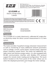
VOLTS
IMBAL
Set Phase Loss:
VOLTS - Phase Loss Voltage: The fraction of the system
voltage below which Phase Loss Alarm is on. For system
types with neutral, the Line to Neutral voltage is also
calculated and tested. If the System Voltage is 600 and the
Back
Phase
Loss
SPLOS
--------
0.10
--------
0.25
Next
fraction is set to 0.10, then the Phase Loss threshold will be
60 volts.
IMBAL - Phase Loss Imbalance: The fractional difference
in Line to Line voltages above which Phase Loss Alarm is
on. For system types with neutral, the Line to Neutral
voltages are also tested. For system types 1+N (10) and 2
(11) , imbalance is not tested.
Back
SPULS
Wh/P
--------
10000
1000
mS/P
--------
500
250
Max
PPS
--------
1
2
Set Pulse:
The System Type , CT size, PT Ratio, and System Voltage must
all be configured before setting the Pulse Energy. If any of these
parameters are changed, the meter will hunt for a new Pulse
Duration, but will not change the Pulse Energy. If it cannot find a
solution, the meter will display the wrench, show ConF in the
ALARM -> PULSE screen, and enable Energy pulse output
configuration error bit in the Modbus Diagnostic Alert Bitmap (if
equipped).
Pulse
Output
100
10
INTRV
--------
6
100
5
50
10
25
20
10
50
Next
SEC
Wh/P - Set Pulse Energy: In Watt Hours (& VAR Hours, if
present) per Pulse. When moving down to a smaller energy, the
meter will not allow the selection if it cannot find a pulse duration
that will allow the pulse output to keep up with Theoretical
Maximum System Power (see S_PWR screen). When moving
up to a larger energy, the meter will jump to the first value where
it can find a valid solution.
mS/P Minimum Pulse Duration Time: This read only value
is set by the meter to the slowest duration (in mS per closure)
that will keep up with the Theoretical Maximum System Power.
The open time is greater than or equal to the closure time. The
maximum Pulses Per Second (PPS) is shown in yellow.
Set Demand Interval:
INTRV - The number of Sub-Intervals (1 to 6) in a Demand Interval.
Back SDMND
5
--------
4
00900
Default is 1 (block demand).
SEC - Sub-Interval length in seconds. Default is 900 (15 minutes).
Demand
3
2
1
Next
Set to 0 for external sync-to-comms (Modbus units only).
Back
S DIS
UNITS
--------
IEEE
Set Display Units: +/- to switch between:
IEEE VLL VLN W VAR VA Units.
Display
Units
IEC
Next
IEC - U V P Q S Units.
Back
Setup
SPASS
SETUP
--------
00000
RESET
--------
00000
Set Passwords:
SETUP - The Password to enter the SETUP menu.
RESET - The Password to enter the RESET menu.
Passwords
Next
To Setup page 1 “S COM”
Installation
G
uide
Power
M
onit
oring
Series 4100 Modbus
TM
17
RS
-485
C
ommunications
D
a
i
s
y
-
c
h
a
i
ni
n
g
D
e
v
i
c
e
s
t
o
t
h
e
Power
M
e
t
e
r
The RS-485 slave port allows the power meter to be connected in a daisy chain format with up to 32 devices, assuming a Leviton Energy
Monitoring HUB as the master device.
120
Ω
terminator
o
n
t
h
e
fi
r
s
t
a
n
d
l
a
s
t
d
e
v
i
c
e
o
f
t
h
e
da
i
s
y
c
h
a
i
n
S
N
o
te
s
S
hi
el
d
wir
e
The
t
e
rm
i
na
l
s
vo
l
t
a
g
e
and
c
u
rr
e
n
t
rat
i
ng
s
a
r
e
c
o
m
p
l
ian
t
with
t
h
e
r
e
qu
i
r
e
m
e
n
t
s
o
f
t
h
e
EIA
R
S
-
485
c
o
mm
un
i
c
at
i
o
n
s
s
t
anda
r
d
.
The
R
S
-
485
t
r
an
s
c
e
i
v
e
r
s
a
r
e
¼
un
i
t
l
o
a
d
o
r
l
e
ss
.
R
S
-
485
+
ha
s
a
47
k
Ω
pu
ll
up
t
o
+
5
V
,
and
R
S
-
485
-
ha
s
a
47
k
Ω
pu
ll
down
t
o
S
h
i
e
l
d
(
R
S
-
485
signal
g
r
o
und
)
.
W
i
r
e
t
h
e
R
S
-
485
bus a
s
a
dai
s
y
c
hain
from device
t
o
device,
without
any
s
t
ub
s
.
U
s
e
120
Ω
termination r
esi
s
t
o
r
s
at
e
ac
h
e
nd
o
f
t
h
e
bus
(
n
o
t
i
n
c
l
ud
e
d
)
.
S
h
i
e
l
d
i
s
n
o
t
internally
c
o
nn
e
c
t
e
d
t
o
E
a
r
t
h
G
r
o
und
.
C
o
nn
e
c
t
S
h
i
e
l
d
t
o
E
a
r
t
h
Ground
s
o
m
e
w
h
e
r
e
o
n
t
h
e
R
S
-
485
bu
s
.
F
o
r
a
ll
t
e
r
m
i
n
a
l
s
:
When
tightening
t
e
rm
i
na
l
s
,
apply
t
h
e
c
o
rr
e
c
t
t
o
r
qu
e
:
0.37
t
o
0.44
f
t
·
lb
(0.5-0.6
N
·
m)
.
U
s
e
14-24 gauge (2.1-0.2
mm
2
)
w
i
r
e.
0.37
0.44
ft•lb
(0.5
0.6
N•
m)
Installation
G
uide
Power
M
onit
oring
Series 4100 Modbus
TM
18
M
odbus
Point
M
ap
O
v
er
vie
w
The
Lo
g
S
t
at
u
s
R
e
g
i
s
t
e
r
ha
s
a
dd
i
t
i
ona
l
error flag
b
i
t
s
t
hat
i
nd
i
c
at
e
w
h
e
t
h
e
r
logging
ha
s
been
r
e
s
e
t
o
r
interrupted
(power
c
y
c
l
e
,
e
t
c
.
)
during
t
h
e
previous demand
s
ub
-i
n
t
e
r
v
a
l
,
and
w
h
e
t
h
e
r
t
h
e
R
ea
l
-
T
i
m
e
C
l
o
c
k
ha
s
been changed
(r
e
-i
n
i
t
ia
l
i
z
e
d
t
o
d
e
f
a
u
l
t
dat
e
/
t
i
m
e
du
e
t
o
a
power-cycle o
r
modified via Modbus
c
o
mm
an
d
s
)
.
The
Series 4100
F
u
ll
Dat
a
S
e
t
(FDS)
model
f
e
at
u
r
e
s
data o
u
t
pu
t
s
such a
s
demand
c
a
lc
u
l
at
i
o
n
s
,
per phase signed
w
at
t
s
V
A
and
V
A
R
,
i
m
p
o
r
t
/
e
x
p
o
r
t
W
h
and
V
A
h
,
and
V
A
R
h
ac
c
u
m
u
l
at
o
r
s
b
y
q
ua
d
r
an
t
.
The
Series 4100
Dat
a
Lo
gg
i
ng
model
i
n
c
l
ud
e
s
t
h
e
F
DS
and
a
dd
s
l
o
g
configuration
r
e
g
i
s
t
e
r
s
155-178 and
l
o
g
buffer reading
at
r
e
g
i
s
t
e
r
s
8000-13760.
The
m
e
t
e
r
s
upp
o
r
t
s
v
a
r
ia
b
l
e
C
Ts
and PTs,
a
ll
o
w
i
ng
a
m
u
c
h
wider range o
f
operation from 90V
x
5
A
up
t
o
32000V
x
32000A.
T
o
p
r
o
m
o
t
e
t
h
i
s
,
t
h
e
m
e
t
e
r
p
e
rm
i
t
s
v
a
r
ia
b
l
e
s
c
a
l
i
ng
o
f
t
h
e
16
-
b
i
t
i
n
t
e
g
e
r
r
e
g
i
s
t
e
r
s
via
t
h
e
s
c
a
l
e
r
e
g
i
s
t
e
r
s
.
The
32-bit floating
p
o
i
n
t
r
e
g
i
s
t
e
r
s
d
o
n
o
t
need
t
o
b
e
s
c
a
l
e
d
.
In
t
e
g
e
r
r
e
g
i
s
t
e
r
s
b
e
g
i
n
at
001 (0x001).
F
l
o
at
s
at
257
(0x101).
C
o
n
fi
gu
rat
i
o
n
r
e
g
i
s
t
e
r
s
at
129
(0x081).
V
a
l
u
e
s
n
o
t
s
upp
o
r
t
e
d
i
n
a
p
a
r
t
i
c
u
l
a
r
S
y
s
t
e
m
Type
configuration
r
e
p
o
r
t
Q
N
A
N
(0x8000
i
n
In
t
e
g
e
r
R
e
g
i
s
t
e
r
s
,
0x7
F
C
00000
i
n
F
l
o
at
i
ng
P
o
i
n
t
R
e
g
i
s
t
e
r
s
)
.
R
e
g
i
s
t
e
r
addresses
a
r
e
i
n
P
L
C
s
t
y
l
e
b
a
s
e
1
notation.
S
ub
t
r
ac
t
1
from
a
ll
addresses
f
o
r
t
h
e
b
a
s
e
0
v
a
l
u
e
used
o
n
t
h
e
Modbus
R
S
-
485
l
i
n
k.
S
u
pp
o
r
t
e
d
Mo
db
u
s
C
o
mm
a
n
d
s
N
o
t
e
:
I
D
S
t
r
i
ng
information
v
a
r
i
e
s
from model
t
o
model.
T
e
x
t
shown here
i
s
an
e
xam
p
l
e
.
C
ommand
D
escription
0x03
Read
H
olding
Regist
ers
0x04
Read
Input
Regist
ers
0x06
Preset
S
ingle
Register
0x10
Preset
Multiple
Regist
ers
0x11
Repor
t
ID
Return
string:
byte0: addr
ess
byte1: 0x11
byte2: #bytes following
w/out
cr
c
byte3:
ID
b
yt
e
=
247
byte4: status
=
0xFF
if
the
operating system
is
used;
status
=
0x00
if
the
reset system
is
used
bytes5+:
ID
string
=
Leviton S4100
Power
Met
er
F
ull
Da
ta
S
et
RUNNING
RS
Version
x.xxx
last
2
bytes: CRC
0x2B
Read
D
evic
e
Identification,
BASIC
implemen
ta
tion
(0x00,
0x01
and
0x02
data),
C
onf
ormit
y
Level
1.
O
bjec
t
values:
0x01:
Leviton
0x02:
S4100
0x03:
V
xx.yyy
,
wher
e
xx.yyy
is
the
OS
version
number
(r
eforma
tt
ed
version
of
the
Modbus
register #7001,
(F
irm
w
ar
e
Version,
O
per
a
ting
S
yst
em).
If
register #7001
==
12345,
then
the
0x03
da
ta
would
be
V12.345”).
L
ege
n
d
The
following
t
a
b
l
e
l
i
s
t
s
t
h
e
addresses assigned
t
o
each data
point.
F
o
r
floating
p
o
i
n
t
format
v
a
r
ia
b
l
e
s
,
each data
p
o
i
n
t
a
pp
ea
r
s
t
w
i
c
e
because
t
w
o
16
-
b
i
t
addresses
a
r
e
required
t
o
h
o
l
d
a
32-bit float
v
a
l
u
e
.
N
e
g
at
i
v
e
signed
i
n
t
e
g
e
r
s
a
r
e
2
s
c
o
m
p
l
e
m
e
n
t
.
Installation
G
uide
Power
M
onit
oring
Series 4100 Modbus
TM
19
R/W
R=r
ead
only
R/W=read
fr
om
either
in
t
or
float
formats, write only
t
o
in
t
eger
f
orma
t
.
NV
Value is
stored
in
non-volatile memor
y.
T
he
value
will
still
be
available
if
the
meter experiences a
po
w
er
loss
and
r
eset.
F
orma
t
UIn
t
Unsigned
16-bit
in
t
eger.
SIn
t
S
igned
16-bit
in
t
eger.
UL
ong
Unsigned
32-bit
in
t
eger;
Upper
16-bits
(MSR)
in
lowest-numbered
/
first
listed register
(001/002
=
MSR/LSR).
SL
ong
S
igned
32-bit
in
t
eger;
Upper
16-bits
(MSR)
in
lowest-numbered
/
first
listed register
(001/002
=
MSR/LSR).
F
loa
t
32-bit
floating point;
Upper
16-bits
(MSR)
in
lowest-numbered
/
first
listed register
(257/258
=
MSR/LSR).
E
nc
oding
is
per
IEEE
standar
d
754
single
pr
ecision.
Units
Lists
the
physical
units
that
a
register holds.
S
c
ale
F
ac
t
or
S
ome
In
t
eger
values
must
be
multiplied
b
y
a
c
onstan
t
sc
ale
fac
t
or
(typically
a
fr
ac
tion),
t
o
be
read
c
orr
ec
tly
.
T
his
is
done
t
o
allo
w
in
t
eger
numbers
t
o
r
epr
esen
t
fractional
numbers.
R
ange
Defines
the
limit
of
the
values
that
a
register
c
an
c
on
tain.
S
etting
V
alue
Modbus
Regist
er
S
etup
Password
00000
Reset
Password
00000
S
yst
em
T
ype
40
(3
+
N)
Wy
e
130
C
T
Primary Ratio
(if
C
Ts
ar
e
not
included)
100A
131
C
T
S
ec
ondar
y
R
a
tio
1V
132
PT
R
a
tio
1:1
(none)
133
S
yst
em
V
oltage
600
V
L
-L
134
Max.
T
heor
etical
Power
(
A
nalog
O
utput:
full
sc
ale
(20mA
or
5V
))
104
kW
135
D
isplay
Mode
1
(IEEE
units)
137
Phase
Loss
10%
of
S
yst
em
V
oltage
(60V
),
25%
Phase
t
o
Phase
Imbalanc
e
142,
143
Pulse
E
nergy
1
(kWh/pulse)
144
Demand:
number
of
sub
-in
t
erv
als
per
in
t
erv
al
1
(block
mode)
149
Demand: sub
-in
t
erv
al
length
900
sec
(15
min)
150
Modbus
A
ddr
ess
001
Modbus
B
aud
R
a
t
e
19200
baud
Modbus
P
arit
y
N
one
Log Read
P
age
0
158
L
ogging
C
onfigur
a
tion
Register
0
159
Log
Register
P
oin
t
er
1
3
(Import
Real
E
nergy
MSR)
169
Log
Register
P
oin
t
er
2
4
(Import
Real
E
nergy
LSR)
170
Log
Register
P
oin
t
er
3
5
(Expor
t
Real
E
nergy
MSR)
171
Log
Register
P
oin
t
er
4
6
(Expor
t
Real
E
nergy
LSR)
172
Log
Register
P
oin
t
er
5
29
(Real
D
emand)
173
Log
Register
P
oin
t
er
6
30
(Reactive
D
emand)
174
Log
Register
P
oin
t
er
7
31
(
A
ppar
en
t
D
emand)
175
Log
Register
P
oin
t
er
8
155
(Mon
th/Da
y)
176
Log
Register
P
oin
t
er
9
156
(
Y
ear/Hour)
177
Log
Register
P
oin
t
er
10
157
(M
inut
es/S
ec
onds)
178
M
odbus
Point
M
ap
O
v
er
vie
w
(
con
t.)
Standard
M
odbus
Default
Setting
s
Installation
G
uide
Power
M
onit
oring
Series 4100 Modbus
TM
20
R
NV SLong
kWh
E
R
NV SLong
kVAh
E
017
Series 4100
Regist
er
M
odbus
Point
M
ap
R/W NV
F
orma
t
Units
Scale
Range
D
escription
001
002
003
In
t
eger
Data:
S
ummar
y
of
Active Phases
-2147483647
t
o
+2147483647
Real
E
nergy
:
N
et
(Import
-
Expor
t)
Real
E
nergy
:
Quadrants 1
&
4
MSR
LSR
MSR
A
cc
umula
t
ed
Real
E
nergy
004
005
R
NV ULong
kWh
E
0
t
o
0xFFFFFFFF
Impor
t
LSR
MSR
(Ph)
006
007
008
009
R
NV ULong
kWh
E
0
t
o
0xFFFFFFFF
Real
E
nergy
:
Quadrants 2
&
3
Expor
t
R
NV ULong
kVARh
E
0
t
o
0xFFFFFFFF
Reac
tiv
e
E
nergy
-
Q
uadr
an
t
1:
Lags
Impor
t
Real
E
nergy
(IEC)
Inductive (IEEE)
Reac
tiv
e
E
nergy
-
Q
uadr
an
t
2:
LSR
MSR
LSR
MSR
A
cc
umula
t
ed
Reac
tiv
e
E
nergy
R
NV ULong
kVARh
E
0
t
o
0xFFFFFFFF
Leads
Expor
t
Real
E
nergy
(IEC)
Inductive (IEEE)
(
Q
h):
010
LSR
Quadrants 1
+
2
C
lear
via
r
eset
011
012
013
R
NV ULong
kVARh
E
0
t
o
0xFFFFFFFF
Reac
tiv
e
E
nergy
-
Q
uadr
an
t
3:
Lags
Expor
t
Real
E
nergy
(IEC)
C
apacitiv
e
(IEEE)
MSR
LSR
MSR
=
Impor
t
Quadrants 3
+
4
=
Expor
t
register 129
014
015
016
R
NV ULong
kVARh
E
0
t
o
0xFFFFFFFF
Reac
tiv
e
E
nergy
-
Q
uadr
an
t
4:
Leads
Impor
t
Real
E
nergy
(IEC)
C
apacitiv
e
(IEEE)
-2147483647
t
o
+2147483647
A
ppar
en
t
E
nergy
:
N
et
(Import
-
Expor
t)
LSR
MSR
LSR
A
cc
umula
t
ed
A
ppar
en
t
E
nergy
(Sh):
R
NV ULong
kVAh
E
0
t
o
0xFFFFFFFF
Apparent: Quadrants
1
&
4
MSR
Impor
t
and
018
019
020
R
NV ULong
kVAh
E
0
t
o
0xFFFFFFFF
Impor
t
Apparent: Quadrants 2
&
3
Expor
t
LSR
MSR
LSR
Expor
t
c
orr
espond
with
Real
E
nergy
021
R
SIn
t
kW
W
-32767
t
o
+32767
T
otal
Instantaneous
Real
(P
)
P
o
w
er
022
R
SIn
t
kVAR
W
0
t
o
32767
T
otal
Instantaneous
Reac
tiv
e
(
Q
)
P
o
w
er
023
R
UIn
t
kVA
W
0
t
o
32767
T
otal
Instantaneous
A
ppar
en
t
(S)
Power
(v
ec
t
or
sum)
024
R
SIn
t
Ratio
0.0001
-10000
t
o
+10000
T
otal
Power
F
ac
t
or
(t
otal
kW
/
t
otal
kVA
)
025
R
UIn
t
Volt
V
0
t
o
32767
Voltage,
L
-L
(U),
average
of
ac
tiv
e
phases
026
R
UIn
t
Volt
V
0
t
o
32767
Voltage, L-N
(
V
),
average
of
ac
tiv
e
phases
027
R
UIn
t
Amp
I
0
t
o
32767
C
urr
en
t
,
average
of
ac
tiv
e
phases
028
UIn
t
Hz
0.01
4500
t
o
6500
F
r
equency
029
R
SIn
t
kW
W
-32767
t
o
+32767
T
otal
Real
Power
P
r
esen
t
D
emand
030
SIn
t
kVAR
W
-32767
t
o
+32767
T
otal
Reac
tiv
e
Power
P
r
esen
t
D
emand
031
R
SIn
t
kVA
W
-32767
t
o
+32767
T
otal
A
ppar
en
t
Power
P
r
esen
t
D
emand
032
R
NV SIn
t
kW
W
-32767
t
o
+32767
T
otal
Real
Power Max.
D
emand
033
R
NV SIn
t
kVAR
W
-32767
t
o
+32767
T
otal
Reac
tiv
e
Power Max.
D
emand
034
R
NV SIn
t
kVA
W
-32767
t
o
+32767
T
otal
A
ppar
en
t
Power Max.
D
emand
035
R
NV SIn
t
kW
W
-32767
t
o
+32767
T
otal
Real
Power Max.
D
emand
036
R
NV SIn
t
kVAR
W
-32767
t
o
+32767
T
otal
Reac
tiv
e
Power Max.
D
emand
037
R
NV SIn
t
kVA
W
-32767
t
o
+32767
T
otal
A
ppar
en
t
Power Max.
D
emand
038
R
UIn
t
Reserved,
r
eturns
0x8000
(
QNAN)
Impor
t
Expor
t
Reset
via
r
egist
er
129
039
040
041
042
R
NV ULong
0
t
o
0xFFFFFFFF
Pulse
C
oun
t
er
1
(Import
Real
E
nergy)
R
NV ULong
0
t
o
0xFFFFFFFF
Pulse
C
oun
t
er
2
(Expor
t
Real
E
nergy)
MSR
LSR
MSR
LSR
C
on
tac
t
C
losur
e
C
oun
t
ers
.
V
alid
f
or
both
pulse
inputs
and
outputs. C
ounts ar
e
shown
in ().
S
ee
register 144
-
E
nergy
P
er
Pulse
f
or
the
W
h
per
pulse
c
oun
t
.
  • Page 1 1
  • Page 2 2
  • Page 3 3
  • Page 4 4
  • Page 5 5
  • Page 6 6
  • Page 7 7
  • Page 8 8
  • Page 9 9
  • Page 10 10
  • Page 11 11
  • Page 12 12
  • Page 13 13
  • Page 14 14
  • Page 15 15
  • Page 16 16
  • Page 17 17
  • Page 18 18
  • Page 19 19
  • Page 20 20
  • Page 21 21
  • Page 22 22
  • Page 23 23
  • Page 24 24
  • Page 25 25
  • Page 26 26
  • Page 27 27
  • Page 28 28
  • Page 29 29
  • Page 30 30
  • Page 31 31
  • Page 32 32
  • Page 33 33

Leviton 41OUM-1M User guide

Category
Measuring, testing & control
Type
User guide

Ask a question and I''ll find the answer in the document

Finding information in a document is now easier with AI