Page is loading ...

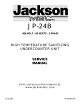
DISHWASHER MODEL 24P-NSU
SPECIFICATION:
440 VOLT - 60 HERTZ - 3 PHASE
HIGH TEMPERATURE SANITIZING
UNDERCOUNTER UNIT
SERVICE MANUAL
DGSC MANUAL NUMBER:
S6161 -A1 -FSC010-17228
INCLUDES:
-Warranty Policy -Installation Requirements
-Operating Instructions -Basic Functions of Dishwasher
-Description of Components -Maintenance and Care
-Troubleshooting Guide -Wiring Diagrams
MANUFACTURING OPERATIONS & WORLD HEADQUARTERS
Highway 25E, P.O. Box1060
Barbourville, KY 40906
888/800-JMSC
Fax: 606/523-9196
January 8, 1999 7610-100-37-00 Rev B

TABLE OF CONTENTS
SPECIFICATIONS 1
INSTALLATION INSTRUCTIONS 2-5
SAFETY PRECAUTIONS 2
UNCRATING 2
INSTALLATION 2
DECK HARDWARE FOR SECURING DISHMACHINE 3
STRAINER INSTALLATION 4
WASH HEAD AND RINSE SPRAY ARM INSTALLATION 5
OPERATION 6
OPERATING INSTRUCTIONS 6
DETERGENT RECOMMENDATIONS 6
CARE AND CLEANING 7-8
GENERAL CLEANING 7
WASH HEAD AND RINSE ARM CLEANING 8
FUNCTIONAL INFORMATION 9-11
SOLID STATE TIMER 9
WATER LEVEL CONTROL 10
SWITCHES, CIRCUIT BREAKER AND INDICATOR LIGHTS 11
SERVICE AND ADJUSTMENTS 12-13
THERMOSTAT ADJUSTMENT 12
INCOMING WATER SOLENOID SERVICE. 13
TROUBLESHOOTING 14-16
ILLUSTRATED PARTS LIST
15-23
PUMP AND MOTOR ASSEMBLY 15
RINSE TANK,WASH ASSY.,THERMOMETERS,THERMOSTATS 16
BOOSTER HEATER, THERMOSTATIC OVERLOAD 17
STRAINER,VACUUM BREAKER/DOOR SWITCH, PLUMBING 18
RIGHT-SIDE ILLUSTRATION 19
BACK-SIDE ILLUSTRATION 20
LEFT-SIDE ILLUSTRATION. 21
WASH AND RINSE ASSEMBLIES 22
DRAIN VALVE AND ELECTRICAL PANEL LAYOUT 23
COMPLETE PARTS LIST AND PART DISTRIBUTORS 24-25
PARTS DISTRIBUTOR LIST 26
WIRING DIAGRAM AND SCHEMATIC 27-28

SPECIFICATIONS
OPERATING CAPACITY
Racks per hour 21
Dishes per hour 525
Glasses per hour 525
OPERATING CYCLE
Wash time-seconds 120
Rinse time—seconds 15
Total Cycle-seconds 150
WASH TANK CAPACITY (Gallons) 5.65
RINSE TANK CAPACITY (Gallons) 3
WASH PUMP CAPACITY (GPM) 60
WATER REQUIREMENTS
Inlet Temperature F. 140
Gallons per hour 52.3
Flow pressure, PSI 20
Flow, gallons per minute 7.1
Inlet size, NPT 1/2"
Drain size, OD 1-1/2"
WASH PUMP MOTOR (HP) 1/2
WASH HEATER (KW) 1.0
RINSE HEATER (KW) 6.7
ELECTRICAL REQUIREMENTS
Volts
440
Phase 3
Cycle 60
TOTAL LOAD AMPS. 17.6
DIMENSIONS
Height, with Top 36"
Height, without Top 34-1/2
Width
28-1/2
Clearance, Wall to Machine 2-1/4
Depth 24"
Maximum height for Dishes 14"
Rack size 19-3/4
[ PAGE 1 ]

INSTALLATION INSTRUCTIONS
SAFETY PRECAUTIONS
Never try to repair or replace any part of the dishwasher unless it is
specifically recommended in this manual. All servicing should be done by a
authorized service technician. There are no user serviceable parts. Safety
precautions in this manual are preceded by the words WARNING or CAUTION and
are very important. WARNING means there is the possibility of personal
injury to yourself or others. CAUTION means there is the possibility of
damage to the machine.
UNPACKING AND INSPECTION STEPS:
1. Remove wooden blocks securing carton to skid and lift box up
and off of machine.
2. Remove bolts securing machine to skid.
The following parts are supplied with the dishmachine and are packed inside
of machine:
1. INSTRUCTION MANUAL
2. STRAINER
3. COMPLETE WASH HEAD ASSEMBLY WITH RETAINING PIN
4. COMPLETE LOWER RINSE ARM ASSEMBLY
5. ADJUSTABLE FEET (4 EACH)
6. DECK MOUNTING TRACKS (2 EACH)
7. DECK MOUNTING TRACK CAPS (4 EACH)
8. TUBE BRUSH
9. RACKS (2 EACH)
[PAGE 2 ]

INSTALLATION INSTRUCTIONS
DECK MOUNTING OF DISHMACHINE
The dishmachine must be secured in place using the deck mounting tracks and caps
provided with machine.
STEPS : REFER TO FIGURE 1
1. Install the (4) adjustable feet provided into screw holes where shipping
bolts were removed earlier.
2. Adjust the level of the dishmachine by screwing the adjustable feet in or
out. The front of the machine should be adjusted 1/4" to 1/2" higher
than the back
3. Install the deck mounting hardware as shown in FIGURE 1 to the deck at
location where dishmachine will be permanently positioned. Install 3/8
inch stainless steel lug bolts to secure tracks and caps to deck.
4. Drill holes into deck as shown in FIGURE 1 and
insure rear holes are located 2-1/4 inch from wall.
5. The tracks and the rear end caps maybe tightened at this time.
6. Slide dishmachine onto tracks and into position at rear end caps.
7. Install front end caps into place and adjust if necessary to remove any
movement of machine, if possible, tack weld tracks to deck.
GRAVITY DRAIN SYSTEM
The drain from the dishmachine is a gravity drain system and should have the proper
drop from the machine to floor drain system.
STEPS : REFER TO FIGURE 2
1. Install hose to drain tube located at left rear of machine as shown in
FIGURE 2. Drain tube is 1-1/2 inches in diameter and 7 inches from floor.
[ PAGE 3 ]

FIGURE 1
INSTALLATION OF DECK HARDWARE TO SECURE DISHMACHINE

INSTALLATION INSTRUCTIONS
STEAM EQUALIZING VENT
The steam equalizing vent is located on the back upper left corner of the
dishmachine. The vent should not be blocked or prevented from venting steam
off from inside of unit. Under-counter machines installed inside of cabinet
are not excluded from this requirement.
STEPS : REFER TO FIGURE 2
1. Install 1-1/4 inch pipe to equalizing vent fitting and connect to
appropriate venting system. NOTE: Do not pipe steam line downward
toward floor, this will restrict venting of steam.
ELECTRICAL POWER CONNECTION
WARNING: All field wiring connections must conform to the Local and National
electrical codes. Install proper circuit breaker, wire and conduit size.
MACHINE DATA PLATE is located at top of inner door.
STEPS : REFER TO FIGURE 2
1. Remove control box side panel and lay aside.
2. Make electrical connection through conduit hole provided at rear of
box and connect 440 VOLT, 60 HZ, 3 PHASE service to terminal block marked
LI, L2 and L3. Connect GROUND WIRE to grounding lug provided.
CAUTION: INJURY OR DEATH MAY OCCUR FROM SHOCK IF MACHINE IS NOT PROPERLY
GROUNDED.
WARNING: DO NOT CONNECT WILD/HOT LEG OF 3 PHASE POWER TO LI OR L2 . CHECK LEGS
TO GROUND FOR PROPER VOLTAGES.
[ PAGE 4 ]

FIGURE 2
LEGEND
A—ELECTRICAL HOOK UP
B—1/2"- F.S.P S. WATER INLET
C—1 1/2" DRAIN CONNECTION
D—EQUALIZING VENT 1 1/4"
REFERENCE ONLY
SUBJECT to CHANGE

INSTALLATION
OF
WASH
SPRAY
HEAD
AND
RINSE
SPRAY ASSEMBLIES
Installation of Wash Head and Rinse Arm Assemblies: (Items disassembled for shipment)
1. Line holes up on wash head assembly to match slots in pump housing.
2. Insert wash head assembly down into upper pump housing as far as possible.
3. Insert retaining pin to secure wash head to pump housing.
[ PAGE 5 ]
1. Line up stud to match with slot in nipple.
2. Insert rinse arm assembly into female receptacle protruding through back of
machine.
3. Insert lanyard pin to secure rinse arm assembly properly.
4. Make certain end plugs are secured properly in rinse tubes.
RINSE ARM ASSEMBLY

GENERAL INSTRUCTIONS
(OPERATION)
Note: Read the following instructions carefully. Proper operation of your Jackson
Dishwasher will assure clean and sanitized glasses and dishes, at optimum efficiency. Dish
Preparation:
1. Scrape dishes thoroughly.
2. Pre-wash dishes by soaking or with hose.
3. Place dishes and cups in dish rack, cups upside down.
4. Place glasses and silverware in combination glass-silverware rack, glasses upside down. Scatter
silverware loosely on bottom.
Note: Silverware in the upright position washes and rinses better than lying flat. These
silverware compartment racks are available through your dealer or Service Agency.
Operating Instructions:
1. Install pan strainer and the wash and rinse arms. Close the door and push until the handle latches.
2. Push the On/Fill-Off/Drain switch to the up 'ON/FILL' position. The machine power light will come on and
so will the rinse heaters. The machine will begin to fill automatically and stop by itself.
3. After the machine has completed filling, open the door and put in a rack of soiled dishes. Close the door.
4. After the door has been closed, the cycle light will come on. There will be a 2-second delay before the
wash cycle begins.
5. The machine will wash for 130 seconds and rinse for 15 seconds. After the cycle has finished, the cycle
light will go out.
6. Open the door and remove the sanitized dishes. The machine is ready for another cycle.
7. To manually wash, push -the manual wash switch to the up 'Manual' position. The machine will wash
indefinitely. This function can also be used to delime. To resume normal operation, push the manual
wash switch to the down 'Auto' position.
8. To drain the machine, close the door and latch. Push the On/Fill-Off/Drain switch to the 'OFF' position.
All machine functions will be off. Push On/Fill-Off/Drain switch down to the momentary drain position.
This will begin the drain cycle. After the machine is drained, it will turn itself off.
9. Open the door. Remove and clean the pan strainer and the wash arms.
10. Wash heater protection is provided by two means. Primary protection is given by the water level control
which senses the water level with a probe. If this should fail due to excessive build up on the probe, the
secondary thermal protection will cut out the wash heater before damage occurs.
11. When the secondary heater protection has been used, it will be indicated by the illuminated red reset
light. The following steps are necessary in this situation:
A. Turn off power supply.
B. Open the door and remove the wash and rinse arms and the pan strainer.
C. Locate the probe. It is in the wash sump on the left hand side.
D. Using a deliming compound and a brush, clean the probe.
E. Reinstall the wash and rinse arms and the pan strainer.
F. Push the reset button, located above the reset light.
G. Push On/Fill-Off/Drain switch to the 'ON/FILL' position. The machine should begin
to fill. If it does not and the reset light comes on again, call an authorized service
agency.
Detergent Recommendations and Rinse Additives:
We suggest that you contact your local Detergent Specialist for the correct detergent and rinse additives for
your area. To help you until one can be reached, we suggest that you use a non-foaming dishwasher
detergent, approximately three tablespoons in wash tank when machine is filled and one teaspoon each
cycle or load thereafter. Dump the detergent on the pan strainer. This may have to be increased or
decreased to obtain satisfactory results.
6

GENERAL INSTRUCTIONS
(PREVENTIVE MAINTENANCE)
(THE FOLLOWING IS TO BE PERFORMED AS NEEDED.)
Note: Read the following instructions carefully. Proper maintenance of your Jackson
Dishwasher will ensure optimum service with a minimum of down time.
1. Remove all lime and corrosion deposits.
a. Fill the machine with wash water as would ordinarily be done for washing.
b. Open door and place one cup or less of de-liming compound into the water. The
compound is available from your detergent supplier.
c. Turn on the manual wash switch and allow to wash for five minutes.
d. Open door and examine the interior. All lime should be removed and parts should be
shiny. If not, allow to wash for longer period.
e. After the interior is clean, with door closed, empty the wash water by turning switch to
the "off/drain" position. Refill machine and allow to run for two minutes, then again
drain the wash reservoir.
2. Clean around overflow strainers and drain hole.
a. Clean around overflow and strainer pan.
b. Clean around pump intake (toothbrush makes excellent tool for cleaning).
3. Clean Y-strainer on incoming water line. (Water to machine must be turned off for this operation)
a. Remove plug and clean strainer.
4. Clean rinse tubes.
a. Remove rinse assembly by disconnecting rinse feed pipe and removing end plugs
on lower rinse.
b. Clean all rinse tubes and feed pipes with special brush supplied.
c. If spray holes in the rinse tubes are clogged, they may be cleaned with a pointed
object.
5. Clean wash head assembly.
a. Remove pin holding wash head assembly to pump.
b. Clean assembly at sink by flushing water through spray jets.
c. If spray jets are still plugged, use sharp object to dislodge and flush again.
d. Reinstall wash and rinse assemblies. (See page with instructions.)
6. Clean any deposits which may have built up on exterior moving parts.
a. Clean around door gasket.
b. Using a soft bristle brush, clean around switches on exterior of control panel. (Use
no water.)
c. Use soft bristle brush, dip in wash tank water and scrub inside door around gasket
and hinges. Use clean cloth or paper towel to wipe off loose residue.
7

REMOVAL of RINSE and/or
WASH HEAD ASSEMBLIES
(GENERAL INSTRUCTIONS)
1. Drain unit by placing switch in the off/drain position.
2. Open the door and allow the unit a few minutes to cool off.
3. Remove the pin holding the rinse feed pipe. Pull the feed pipe out of the nipple and lay it to one side.
4. Remove wash head assembly by pulling out the holding pin and lifting assembly. Place the wash head
on a table for disassembly.
5. Locate Allen head set screw in the wash head cap, insert Allen wrench and loosen screw by turning
counterclockwise.
6. Turn wash head cap counterclockwise until cap is removed and put cap in safe place.
7. Remove ¼” stainless ball bearings carefully and put it in a receptacle in a safe place.
8. Lift and remove small manifold with short tubes. Put it in a safe place.
9. Remove ¼” ball bearing in similar method to step #7.
10. Lift and remove large manifold with large length tubes similar to step #8.
11. Clean ball bearings by soaking in de-liming solution.
12. Ball bearing race ways may be cleaned by either brushing with de-liming solution (toothbrush makes
excellent tool) or gently clean by rubbing with fine sandpaper or emery cloth.
13. Rinse ball bearings and manifolds thoroughly.
14. To reassemble, first fill lower race to capacity with ¼” ball bearings, then remove one. This will give
proper movement needed during rotation of assembly.
15. Replace lower manifold and fill race fully with ¼” ball bearings. Repeat, removing one only.
16. Replace upper manifolds and repeat necessary parts of step #14.
17. Replace wash cap by screwing on center shaft clockwise, finger tight.
18. Back off wash cap about 1/4 turn and tighten Allen set screw.
19. Rotate manifolds in opposite directions; see if they rotate freely. A rule of thumb is to select the longest
tube in the bottom manifold and make sure it moves up and down at least 1/8” and no more than ¼”.
20. Replace wash head assembly and rinse arm.
21. Close the front door and refill dishwasher.
22. Run .through several cycles and recheck wash arms for easy movement. Adjust if necessary.

TIMER for MODEL 24
DISHWASHERS
General Description:
The timer is a solid state, 4 channel CMOS device with a 120V, 50 or 60 cycle, 1 amp rating. AH
components are environmentally encapsulated and quick connect terminals are marked (or corresponding
wires.
Principle of Operation:
Wash cycle function: (Machine must fill before cycle will start.) Upon closure of door switch. cycle light will
come on and remain on for the 150-second cycle. At the same time, a 2-second rinse preheat Interval will
begin. After the preheat, the wash cycle will start and last 130 seconds. Between wash and rinse, there Is a
4-second dwell followed by a 15-second rinse. Cycle by opening and closing door switch at the end of cycle
or at any point In the cycle.
Drain cycle function: (Power switch must be in off position and door switch closed.) When power switch is
pushed to the drain position and released, a holding circuit is established between R4 drain relay and the
timer. The machine will drain for 60 seconds and then break the holding circuit. Cycle is reset by opening
and closing door switch and pushing power switch to drain and releasing.
9
Timer
P/N 0174400

WATER LEVEL CONTROL
AS USED ON 24
P/N 0204400 (110V, 60 cycle)
Function:
The water level control device is utilized on this machine to automatically control the filling of the wash tank and the
activation of the wash tank heater.
Note: All electrical checks should be made by qualified service personnel.
The control is a single probe resistance sensing device designed to maintain water level. When water level reaches the
probe and covers it, a fixed time delay of 25 seconds is initiated. When the delay times out, the electromechanical relay
energizes, opening the 'Auto/Fill' circuit and closing the wash heater circuit. If the water level drops below the probe,
the relay will de-energize, opening the wash heater circuit and closing the 'Auto/Fill' circuit.
Symptoms of Level Control Failure:
1. 'Auto/Fill' will not shut off when water reaches the proper level.
2. Machine will partially fill.
Proceed with Checkouts:
1. Remove power source to machine by moving circuit breaker to "OFF" position.
2. Remove screws holding lower kick plate to the front of machine and locate water level control. (See sketch below.)
3. Remove, mark and insulate (for easy replacement), wires going to pin numbers 4 and 5.
4. Re-apply power. Turn on 'ON/FILL' switch. With an insulated wire, connect jumper wire between pins 4 and 5. (12
volt system)
5. Wait for 25 seconds. The electromechanical relay will energize. If this occurs, control can be deemed operational:
then other causes should be explored.
6. If relay doesn't operate, replace control.
7. Remove power source once again and replace wires that were removed in step three to original pins. (See trouble
shooting section for other possible causes.)
10

FUNCTION of SWITCHES, CIRCUIT
BREAKER and INDICATING LIGHTS
This switch serves as the main control for the unit. When pressed into the 'on' position, it
activates the heater controls, the automatic fill and readies the unit for the wash cycle.
When turned off, all power is off. When pushed to drain position and released, the unit will
drain and turn itself off.
This light comes on when the unit is turned on and goes off when the unit is turned off.
Located on top of the unit, behind the latch bracket, this switch serves three functions.
When the door is opened, it will reset the timer to the cycle starting position. When door is
closed, it will start the automatic cycle. If door should be opened during a cycle, it would
act as a safety switch by turning the unit off.
This green light comes on only when the automatic cycle is in progress and goes off when
the cycle is complete.
This switch is used to bypass the timer and operate the wash pump manually. The wash
pump will run as long as this switch is 'on'. Its prime purpose is to extend the wash period
for heavily soiled dishes, but it may be used for deliming.
This is the reset button on a thermostatic overload. Its purpose is to provide a secondary
protection for the wash tank heater element. If the heater element should come on while
the wash tank is empty, this button would pop out, turning off the element and signaling a
problem with the automatic fill.
This light comes on only when the heater reset trips off. Its purpose is to signal that there
is a problem.
11
On/Fill
Off/Drain
Switch:
P/N 0155600
Power Light:
P/N 0083518
Door Switch:
P/N 0164000
Cycle Light:
P/N 0083507
Manual Wash
Switch:
P/N 0159700
Heater Reset
Button:
P/N 0169601
Reset Light:
P/N 0083518

THERMOSTAT ADJUSTMENT
The thermostat can be adjusted by turning screw #1 (see picture) on the thermostat control box cover.
(Remember the present setting. In case the problems are elsewhere In the control circuit.) A CW rotation is
used to obtain a lower temperature setting and a CCW rotation is used to obtain a higher temperature setting.
A 1/4 turn of screw #1 changes the temperature approximately 15 F. If screw #1 Is turned all the way to its
stop in either direction, adjust screw #2 as follows.
Note: Do not touch the screw sealed with red paint. When adjusting screw #2, power should be
disconnected during adjustment.
Set screw #1 so that it can be turned equal distances in either direction, then:
— if screw #1 stopped while turning in CW direction, turn screw #2 in CW direction, slowly and only 1/8 of a
turn or less per complete cycle of the unit.
— If screw #1 stopped while turning in CCW direction, turn screw #2 in CCW direction, slowly and only
1/4 of a turn or less per complete cycle of the unit:
Three-fourths of a turn will bring the thermostat to approximately the same setting obtained where screw #1
stopped. Check the present temperature setting before attempting any further adjustments. Use screw #1 for
any further adjustments.
Making large moves In adjusting may cause misalignment, thus increasing chances that further adjustment-
cannot be made and thermostat will have to be replaced.
12
Thermostat
P/N 0170018 Rinse
0170023 Wash
SCREW #1

SERVICE INSTRUCTIONS
(INCOMING WATER SOLENOID VALVE)
SOLENOID VALVE
P/N 1420 (110V, used on 60 cycle machine
P/N 1425 (220V, used on 50 cycle machine)
To take the valve apart:
Disassembly — These valves may be taken apart by
unscrewing the bonnet and the enclosing tube assembly from
the valve body assembly. See Fig. 3. After unscrewing,
carefully lift off the bonnet and enclosing tube assembly. Don’t
drop the plunger. The “O” ring seal and diaphragm cartridge
can now be lifted out.
Be careful not to damage the machined faces while the valve is
apart.
To Reassemble – Place the diaphragm cartridge in the body
with the pilot port extension UP. Hold the plunger with the
synthetic seat against the pilot port. Make sure the “O” ring is
in place, then lower the bonnet and enclosing tube assembly
over the plunger. Screw bonnet assembly snugly down on the
body assembly.
DIAPHRAGM CARTRIDGE
Possible Problems
Pilot Port extension #1 clogged
Hole #2 clogged
Pass heated
straight pin
through hole
#2 or clean
hole #1.
Remedy
P/N 1435 (60 CYCLE)
P/N 1440 (50 CYCLE)
P/N 1455
P/N 1450

TROUBLE SHOOTING GUIDE
PROBLEM Water overflow out bottom of front
door when wash pump is operating.
CAUSE Machine not level.
Overflow drain clogged.
SOLUTION Level machine.
Slight tilt to rear
Remove obstruction, checking inside of machine
first.
Water level in machine's wash reservoir too high.
Solenoid valve not closing at end of fill or rinse
cycle causing excessive water problem.
Detergent foaming. Reduce quantity of detergent.
Wash motor doesn't operate on manual wash.
Wires broken or loose.
C
heck all wires in the motor and reconnect as
necessary.
Defective manual wash switch. Replace.
Bad bearing, noticeable by noisy bearings or locked
drive shaft.
Replace.
Defective motor starting relay. (Typical • motor
hums.)
Replace.
Note: The motor starting relay is utilized to insert a starting field in the wash pump motor, once the motor has gained speed, the running winding will
then take over and the starting winding will be removed when the relay kicks out. This relay is the amperage sensing type.
Motor runs on manual wash but doesn't operate
on automatic (rinse operates okay on both
manual and automatic cycles.)
Defective center micro switch of timer.
Defective circuit in manual wash switch.
Replace switch.
Replace switch.
No water come
s through the rinse arms when
the rinse fill switch is depressed.
Hand water valve to machine not turned on. Turn on water valve.
Defective coil on solenoid valve. Replace coil.
Broken or loose wires. Repair or reconnect.
Defective manual rinse fill switch. Replace.
Little or no water coming through rinse
assemblies.
Limed up rinse heads or piping.
Begin by cleaning rinse heads using instructions
for de-
liming. If this isn't satisfactory, then clean
the rinse feed pipes.
Water pressure low. Increase pipe size to machine.
14

TROUBLE SHOOTING GUIDE
PROBLEM CAUSE SOLUTION
Rinse doesn't operate on Micro switch defective Replace.
automatic during timed cycle
(this is the micro switch
(but does operate on manual
furthest from the timer motor
rinse/fill operation). on the timer assembly).
Rinse fill switch defective Replace.
on N.C. contacts.
Rinse water runs continuously Defective plunger In Replace plunger.
with circuit breaker controlling
solenoid valve.
machine turned off.
Detective diaphragm in Check both holes in diaphragm
solenoid valve.
cartridge to Insure that they
are open. The one on the outside
perimeter should be the size of an
ordinary straight pin. If it's not.
heat a straight pin and put It
through this hole to enlarge. If
this fails to correct situation.
replace diaphragm.
Note: In disassembling solenoid valve, use instructions shown on separate page.
Rinse water runs Defective rinse/flll switch. Replace.
continuously with power applied
to machine, but when circuit Defective timer that has Replace timer motor or
breaker to machine Is turned
stopped In a position
timer as necessary
off, water stops. keeping the rinse on.
Defective micro switch on Replace.
timer assembly.
Note: Excessive water line pressure can cause water to continually run even though the power to the machine is turned off. Check
specifications for required pressure.
Wash temperature not at Defective thermometer. Using a thermometer (fast
required reading on
reading type that's known
thermometer.
to be correct), insert In wash
reservoir and check reading
against wash thermometer on
machine. If machine thermometer
isn't correct within three or four
degrees, replace.
Rinse temperature not at Check out rinse heat using
required temperature, causing
heater checkout system page
wash temperature to be
in manual.
lowered during rinse cycle.
Note: Any switches, water level controls, heater elements, relays or contactor that have to be checked out, can be done using the
heater checkout system page.
15

TROUBLE SHOOTING GUIDE
PROBLEM CAUSE SOLUTION
Heater switch defective. Replace.
Water level protection
Replace.
control defective.
Heater element defective. Replace.
Wires loose or burned off. Retighten or Replace.
Rinse water not at required
Thermometer's defective.
Replace.
temperature range.
Heater switch defective. See page on heater system
checkout.
Thermostat defective. Adjust using Instructions on
thermostat page and heater
system's checkout page.
Replace it necessary.
Defective neater relay on If defective, replace. See note
. contactor. on heater system above.
After filling machine with
Overflow-drain clogged.
Clean away obstruction.
water. leakage began at
lower front panel without
machine operating or at and
of rinse cycle.
Machine doesn't drain when Drain solenoid clogged. Remove obstruction.
drain switch is depressed.
Defective switch. Replace.
Defective motor or
Replace.
motor start relay.
Defective drain solenoid. Replace.
Note: The drain pump of this machine is part of wash motor, so if wash motor operates property drain system should work.
16
/