Page is loading ...

ST-BT03Q
12/24VDC Auto Sensing Multi Purpose Tester
Manual
Performs the following tests:
Continuity Voltage Polarity
Load Voltage Drop PTC Fuse
Features:
• Test 12VDC and 24VDC
• Perform 6 different tests
• Verify circuit continuity via:
- LED
- LED + Buzzer
• Auto-sensing 12VDC/24VDC
• Built-in LED light
• 4 selectable loads for simulating
realistic test conditions
• Internal battery included
This tester is not intended for testing AC. Indication of AC voltage is for warning purposes only.
Note: Products with model numbers that end with “Q” or that have a round green “Q” sticker are RoHS compliant.

ENFORCER
®
12/24VDC Auto Sensing Multi Purpose Tester
2 SECO-LARM
®
U.S.A., Inc
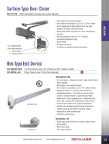
Overview:
1. LED Light switch
- Turn LED light ON/OFF
2. Test Mode switch
- Voltage Test
- Continuity Test (LED)
- Continuity Test (LED + Buzzer)
3. Load Selection
1
switch
- 1.0A (for 12VDC)
- 0.5A (for 12VDC)
- 0.5A (for 24VDC)
- 0.25A (for 24VDC)
4. LED Light
5. DC Jack
6. Polarity Indicator LED
- Blue: Correct polarity
- Red: Incorrect polarity
- Purple: Caution, AC voltage
present
2
7. Power Indicator LED
- Red: Testing 12VDC
- Blue: Testing 24VDC
8. Test Done Indicator
- Wait 30 seconds before next test
9. Continuity Indicator LED
- When lit, circuit has continuity
10. Power Level
- Red: Bad
- Yellow: Weak
- Green: Good
- Blue: Excellent
- See testing instructions for
details.
11. Load Button
- Select load via switch 3
- Press to apply selected load
1
Test voltage before choosing load. Using loads for the incorrect voltage may result in incorrect readings.
2
This tester is not intended for testing AC. Indication of AC voltage is for warning purposes only.
IMPORTANT NOTES:
1. Battery protector must be removed before use.
2. Do not perform continuity tests on live or powered circuits. Performing continuity tests on live or powered
circuits may damage the tester.
3. The polarity indicator LED will show purple to indicate AC power is present. Do not perform any tests
when AC power is present.
4. The tester is intended to test 12VDC or 24VDC. Do not exceed 30VDC.
5. Load testing takes no longer than a few seconds. Significant heat is normal when load testing but
pressing the load button for too long will cause the unit to overheat and shutdown.
6. When load testing, wait 30 seconds between tests to allow the unit to cool.
7. Always store the unit in Voltage Test mode to prevent draining to battery.
8. The LED Light is for providing temporary illumination. Extended use will quickly exhaust the batteries.
Specifications:
Operating voltage
12VDC and 24VDC (auto sensing)
Simulated load
For 12VDC
0.5A@12VDC and 1.0A@12VDC
For 24VDC
0.25A@24VDC and 0.5A@24VDC
Power
Continuity: 2x 3VDC button cell (CR2016)
Other tests: Passive, no power required
Weight
2.2-oz (62g)
Dimensions
2
9
/
16
”x1
15
/
16
”x1
1
/
8
” (65x49x29 mm)
NOTE: Ensure the circuit is unpowered.
1. Set test mode to LED or LED + Buzzer.
2. Connect the alligator clips to the circuit being tested.
3. LED indicator will light and/or buzzer will sound if
circuit is continuous.
IMPORTANT: 1. Remove battery protector before use.
2. When test
done, reset test mode to Voltage.
Continuity
Example Test Application
NOTE:
Only test unpowered circuits
Continuity
I
ndicator
LED
Set test mode to
LED or
LED + Buzzer

12/24VDC Auto Sensing Multi Purpose Tester ENFORCER
®
SECO-LARM
®
U.S.A., Inc 3
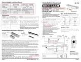
Power LED Color
LED Color
Red (12VDC)
Blue (24VDC)
Blue
12.0 ~ 16.4
≥ 24.5
Green
10.9 ~ 11.9
22.6 ~ 24.4
Yellow
10.2 ~ 10.8
21.0 ~ 22.5
Red
9.5 ~ 10.1
19.5 ~ 20.9
LED Off
≤ 09.4
16.5 ~ 19.4
1. Set test mode to Voltage.
2. Check voltage and choose load.
3. Connect tester.
4. Press load button and read voltage
according to the chart in Test 2.
1. Set test mode to Voltage.
2. Check voltage and choose load.
3. Check voltage at source.
4. Check voltage at device
5. Compare: The voltage drop is the difference between voltage at the power source and voltage at the device-end.
1. Wait 30 seconds for tester and fuse to cool before/after performing tests.
2. Connect the alligator clips to the leads/terminals of the fuse being tested.
3. Choose a test load of the correct voltage and with amperage more than the
current draw of the camera or other device to be connected.
4. Press and hold LOAD button for about 3 seconds.
5. Read fuse condition according to the table on the right.
6. If the fuse tests “Yellow/Weak” or “Red/Bad”:
− Test another fuse. If result is the same, load may be too much. Try a smaller load.
− If test still yields “Weak” or “Bad,” replace the fuse.
PTC Fuse
1.0A / 12VDC
0.5A / 12VDC
0.5A / 24VDC
0.25A / 24VDC
Voltage Drop
1.0A / 12VDC
0.5A / 12VDC
0.5A / 24VDC
0.25A / 24VDC
Load
LED Color
Polarity
No color
No voltage present
Blue
Correct polarity
Red
Incorrect polarity
Purple
AC voltage present
Do not test further
1. Set test mode to Voltage.
2. Connect the alligator clips to the wires or terminals of the
device being tested.
OR
Connect the 2.1mm DC plug of any 12 or 24VDC power
source to the tester’s 2.1mm DC jack directly.
3. The Polarity Indicator LED will show the polarity of the
power present according to the table on the right.
Polarity
NOTE: Test 12/24VDC only.
Do not test VAC or >30VDC.
1.
Set test mode to Voltage.
2.
Connect the alligator clips to the wires or terminals
of the device being tested.
3.
Power level LEDs will indicate power as shown in
the table on the right.
Voltage with auto sensing
LED Color
Fuse Condition
Blue
Excellent
Green
Good
Yellow
Weak
Red/
All LEDs Off
Bad, replace fuse
Polarity
Indicator
LE
D
Power Level LEDs
Center pin positive
Do not hold
load button
for more
than 10s
a. Check Voltage
Red:12VDC
Blue: 24VDC
b.
Choose Load
See left
a. Check Voltage
Red:12VDC
Blue: 24VDC
b.
Choose Load
See left
Note:
All
values
±5%

ENFORCER
®
12/24VDC Auto Sensing Multi Purpose Tester
4 SECO-LARM
®
U.S.A., Inc
Changing the battery (Use CR2016 3VDC battery x2):
1. Unscrew the rear panel.
2. Gently remove the circuit board starting from the end opposite the DC jack.
3. Note the orientation of the button cell batteries and remove them.
4. Replace the batteries with two fresh cells of the same type (CR2016), in the same orientation as before.
5. Carefully replace the circuit board in the housing, taking care that the LEDs align with the holes.
Troubleshooting:
Battery load test fails
• Charge the battery fully for best results.
• Replace battery being tested.
Voltage drop test fails
• Use SECO-LARM ST-HB105-TTQ Voltage Booster to
increase the voltage.
• Reduce length of wiring.
• Use a lower gauge wire.
PTC fuse test fails
• Check PTC soldering to make sure it is correctly applied.
• Replace PTC fuse.
Continuity test yields false negative
• Change the internal battery.
(Be sure to store tester in Voltage Test mode.)
Internal battery depletes quickly
• Be sure to store tester in Voltage Test mode.
• Avoid prolonged use of the LED Light.
Also Available from SECO-LARM:
6-in-1 12VDC Battery Tester
ST-BT02Q
Latching Continuity Tester
ST-BL01Q
Illuminated Power Connectors
CA-1610-3FLQ / CA-1510-3FLQ
WARRANTY This SECO-LARM product is warranted against defects in material and workmanship while
used in normal service for a period of one (1) year from the date of sale to the original consumer customer.
SECO-LARM’s obligation is limited to the repair or replacement of any defective part if the unit is returned,
transportation prepaid, to SECO-LARM. This Warranty is void if damage is caused by or attributed to acts of
God, physical or electrical misuse or abuse, neglect, repair, or alteration, improper or abnormal usage, or
faulty installation, or if for any other reason SECO-LARM determines that such equipment is not operating
properly as a result of causes other than defects in material and workmanship. The sole obligation of
SECO-LARM, and the purchaser’s exclusive remedy, shall be limited to replacement or repair only, at
SECO-LARM’s option. In no event shall SECO-LARM be liable for any special, collateral, incidental, or
consequential personal or property damages of any kind to the purchaser or anyone else.
NOTICE: The information and specifications printed in this manual are current at the time of publication.
However, the SECO-LARM policy is one of continual development and improvement. For this reason,
SECO-LARM reserves the right to change specifications without notice. SECO-LARM is also not
responsible for misprints or typographical errors.
Copyright © 2011 SECO-LARM U.S.A., Inc. All rights reserved. This material may not be reproduced or
copied, in whole or in part, without the written permission of SECO-LARM.
SECO-LARM
®
U.S.A., Inc.
16842 Millikan Avenue, Irvine, CA 92606 Website: www.seco-larm.com
Tel: 800-662-0800 / 949-261-2999 Fax: 949-261-7326 E-mail: sales@seco-larm.com
Order Part # 763-169%
MiST-BT03Q_1109.docx
PITSW1
/