Page is loading ...

1
© Copyright 2007, PROTECTA
IMPORTANT: If you have any questions on the use, care,
application, or suitability for use of this safety equipment,
contact PROTECTA.
IMPORTANT: Before using this equipment, record the
product identifi cation information found on the ID label of
your rope grab in the inspection and maintenance log in
section 9.0 of this manual.
1.0 APPLICATION
1.1 PURPOSE: PROTECTA rope grab fall arresters are
intended to be used as part of a personal fall arrest or
restraint system. Applications for this type of product
include: inspection work, construction and demolition,
maintenance, oil production, window washing, and
other activities where the need exists for fall arrest or
restraint. See Figure 2. The following defi nitions describe these applications:
A. FALL ARREST: The rope grab is used as part of a complete fall arrest system. Such systems generally
include: a lifeline, rope grab, lanyard, and full body harness (body support). Applications include:
protection of a worker on scaffolding, powered platforms, or riding a boatswain’s chair. Maximum
permissible free fall is 6 feet.
B. RESTRAINT: The rope grab is used in combination with a lifeline, lanyard or connector, and body
support to restrain the user from reaching a hazard (sloped or leading edge roof work). No vertical free
fall is possible.
1.2 THE FOLLOWING APPLICATION LIMITATIONS MUST BE CONSIDERED BEFORE USING THIS
PRODUCT:
A. CAPACITY: This equipment is designed for use by persons with a combined weight (person, clothing,
tools, etc.) of no more than 310 lbs. NOTE: No more than one person may be attached to a single
lifeline.
USER INSTRUCTION MANUAL COBRA ROPE GRABS
This manual is intended to meet the Manufacturer’s Instructions as required by CSA Z259.2.1
in Canada and ANSI Z359.1, and should be used as part of an employee training program as
required by OSHA
WARNING: This product is
part of a personal fall arrest
or restraint system. The user
must follow the manufacturer’s
instructions for each component
of the system. These instructions
must be provided to the user of
this equipment. The user must
understand these instructions
before using this equipment.
Manufacturer’s instructions must
be followed for proper use and
maintenance of this product.
Alterations or misuse of this
product, or failure to follow
instructions may result in serious
injury or death.
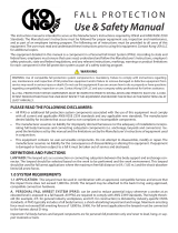
Figure 1 - Cobra Rope Grab
Dimple
Attachment
Eye
Opening Lever
Hinge
Lock Pin
Locking Arm
Spring
Lifeline
Channel
Auto-locking Lever
Locking Cam
Release Button
Groove
Lock Ring
Instructions for the following series products:
Cobra Rope Grabs
(See back page for specifi c model numbers.)
Figure 2 - Applications
Fall Arrest
Restraint
Lifeline
Lifeline
Lanyard
Rope Grab
Lanyard
Rope Grab

2
B. FREE FALL: Restraint systems must be rigged such that there is no possible vertical free fall. Personal
fall arrest systems must be rigged in such a way to limit the free fall to 6 feet (ANSI Z359.1). See
associated connecting subsystem manufacturer’s instructions for further information.
C. FALL CLEARANCE: Make certain that enough clearance exists in your fall path to prevent striking an
object. The amount of clearance required is dependent upon the type of connecting subsystem used
(lanyard, lifeline), the anchorage location, and the amount of stretch in the lifeline. See section 3.2 for
more information on determining fall clearance.
D. CORROSION: Do not leave this equipment for long periods in environments where corrosion of metal
parts could take place as a result of vapors from organic materials. Sewage and fertilizer plants, for
example, have high concentrations of ammonia. Use near seawater or other corrosive environments
may require more frequent inspections or servicing to ensure corrosion damage is not affecting the
performance of the product.
E. CHEMICAL HAZARDS: Solutions containing acids, alkali, or other caustic chemicals, especially at
elevated temperatures, may cause damage to this equipment. When working with such chemicals,
frequent inspection of this equipment must be performed. Consult PROTECTA if doubt exists concerning
using this equipment around chemical hazards.
F. HEAT: This equipment is not designed for use in high temperature environments. Protection should be
provided for this equipment when used near welding, metal cutting, or similar activities. Hot sparks may
burn or damage this equipment. Consult PROTECTA for details on high temperature environments.
G. ELECTRICAL HAZARDS: Due to the possibility of electric current flowing through this equipment or
connecting components, use extreme caution when working near high voltage power lines.
H. COMPONENT COMPATIBILITY: The rope grab addressed by these instructions is intended for use
with PROTECTA lifelines and lifeline subsystems only. Consult PROTECTA if you are considering using this
equipment with other lifelines or lifeline subsystems. See section 2.0.
I. TRAINING: This equipment is to be used by persons who have been properly trained in its correct
application and use.
1.3 Refer to applicable local, state, and federal (OSHA) requirements governing this equipment for more
information on rope grabs and associated system components, including; ANSI Z359.1, and OSHA 1910.66,
appendix C.
2.0 SYSTEM REQUIREMENTS
2.1 COMPATIBILITY OF COMPONENTS: PROTECTA equipment is designed for use with PROTECTA approved
components and subsystems only. Substitutions or replacements made with non-approved components
or subsystems may jeopardize compatibility of equipment and may effect the safety and reliability of the
complete system.
2.2 COMPATIBILITY OF CONNECTORS: Connectors are considered to be compatible with connecting
elements when they have been designed to work together in such a way that their sizes and shapes do
not cause their gate mechanisms to inadvertently open regardless of how they become oriented. Contact
PROTECTA if you have any questions about compatibility.
Connectors (hooks, carabiners, and D-rings) must be capable of supporting at least 5,000 lbs. (22.2 kN).
Connectors must be compatible with the anchorage or other system components. Do not use equipment
that is not compatible. Non-compatible connectors may unintentionally disengage. See Figure 3. Connectors
must be compatible in size, shape, and strength. Self-locking snap hooks and carabiners are required by
ANSI Z359.1 and OSHA.
2.3 MAKING CONNECTIONS: Only use self-locking snap hooks and carabiners with this equipment. Only use
connectors that are suitable to each application. Ensure all connections are compatible in size, shape and
strength. Do not use equipment that is not compatible. Ensure all connectors are fully closed and locked.
PROTECTA connectors (snap hooks and carabiners) are designed to be used only as specifi ed in each
product’s user instructions. See Figure 4 for inappropriate connections. PROTECTA snap hooks and
carabiners should not be connected:
A. To a D-ring to which another connector is attached.
B . In a manner that would result in a load on the gate.

3
NOTE: Large throat-opening snap
hooks should not be connected to
standard size D-rings or similar
objects which will result in a load
on the gate if the hook or D-ring
twists or rotates. Large throat snap
hooks are designed for use on fi xed
structural elements such as rebar or
cross members that are not shaped
in a way that can capture the gate of
the hook.
C. In a false engagement,
where features that protrude
from the snap hook or
carabiner catch on the
anchor, and without visual
confirmation seems to be
fully engaged to the anchor
point.
D. To each other.
E. Directly to webbing or rope lanyard or tie-back (unless the manufacturer’s instructions for both the
lanyard and connector specifically allows such a connection).
F. To any object which is shaped or dimensioned such that the snap hook or carabiner will not close and
lock, or that roll-out could occur.
2.4 ANCHORAGE STRENGTH: The anchorage strength required is dependent upon the application. The
following lists guidelines for specifi c application types:
A. FALL ARREST: Anchorages selected for personal fall arrest systems (PFAS) shall have a strength
capable of sustaining static loads, applied in the directions permitted by the PFAS, of at least: (A) 3,600
lbs. (16 kN) when certification exists (see ANSI Z359.1 for certification definition), or (B) 5,000 lbs.
(22.2 kN) in the absence of certification. When more than one PFAS is attached to an anchorage, the
anchorage strengths set forth in (A) and (B) above shall be multiplied by the number of personal fall
arrest systems attached to the anchorage.
Per OSHA 1926.500 and 1910.66: Anchorages used for attachment of PFAS shall be independent of
any anchorage being used to support or suspend platforms, and capable of supporting at least 5,000
lbs. (22.2 kN) per user attached, or be designed, installed, and used as part of a complete PFAS, which
maintains a safety factory of at least two, and is supervised by a qualified person.
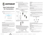
Figure 4 - Inappropriate Connections
If the connecting element that a snap hook (shown) or carabiner attaches to is undersized or irregular in shape, a
situation could occur where the connecting element applies a force to the gate of the snap hook or carabiner. This force
may cause the gate (of either a self-locking or a non-locking snap hook) to open, allowing the snap hook or carabiner to
disengage from the connecting point.
1. Force is applied to the
snap hook.
2. The gate presses against
the connecting ring.
3. The gate opens allowing the
snap hook to slip off.
Figure 3 - Unintentional Disengagement (Roll-out)
Small ring or
other
non-compatibly
shaped element

4
B. RESTRAINT: Anchorages must be capable of supporting a minimum of 3,000 lbs. per system attached.
WARNING: Restraint anchorages may only be used where there is no possible vertical free fall. Restraint
anchorages do not have suffi cient strength for fall arrest. Do not connect personal fall arrest systems to restraint
anchorages.
2.5 LIFELINES: PROTECTA rope grabs are to be used with PROTECTA lifelines and lifeline subsystems. Lifelines
used with all Cobra rope grabs are: 5/8-inch (16mm) diameter polyester/polypropylene blend rope
assembly, 5/8-inch (16mm) diameter polyester/polypropylene blend rope, 5/8-inch (16mm) diameter
polyester rope assembly, 5/8-inch (16mm) diameter polyester, 5/8-inch (16mm) diameter polyester
kernmantle rope assembly, 5/8-inch (16mm) diameter polyester kernmantle rope. See Section 7.3 for
Lifeline specifi cations. See appropriate lifeline instructions for rope elongation factors. The following lifeline
requirements must be followed:
A. SIZE: The 5000335 rope grab is designed to be used on 5/8-inch (16mm) diameter lifeline. Undersized
rope may not allow the rope grab to lock properly and may cause excessive stopping distances.
Oversized rope may impede rope grab mobility on the lifeline. It is recommended that lifeline diameter
be 5/8 inch, ±1/32 inch (0.8mm).
B. CONSTRUCTION: Kernmantle or 3-strand lay ropes are recommended. Consult PROTECTA if you are
considering using this equipment with other lifeline constructions. Braided, double braided, hollow
braided, or other types of rope constructions must not be used. When selecting the lifeline, choose a
rope with a firm lay. Inspect the lay of the rope by grasping it several feet from the end between the
thumb and index finger. You should not be able to easily squeeze or flatten the rope. Untwisting should
be difficult and the rope should spring back to its original shape.
C. MATERIAL: PROTECTA recommends selecting lifeline ropes made from polyester fibers. Polyester
has less stretch and less swelling due to moisture absorption than nylon. Ropes made solely of
polypropylene, polyethylenes, or other olefins must not be used. Ropes made from cotton, sisal, hemp,
abaca (manila), or other plant/animal fibers must not be used. ANSI Z359.1 requires rope used in
vertical lifelines to be made of virgin synthetic materials having strength, aging resistance, abrasion
resistance, and heat resistance characteristics equivalent or superior to polyamides.
D. STRENGTH: Select a lifeline which, when terminated and installed, will retain a minimum strength of
5,000 lbs. (22.2 kN) per ANSI Z359.1. Selection must account for strength reduction factors, such as
sharp edges and degrading factors (i.e. chemicals).
NOTE: Per ANSI Z359.1: Knots shall not be used for load bearing end terminations, but may be an acceptable
means of securing the free end of the lifeline at ground level.
2.6 LANYARD: Cobra rope grabs must not be used with lanyards other than those specifi ed below:
USA: 3 feet (0.9m) overall connecting subsystem length.
CANADA: AC203 all versions with attached connecting subsystems only of 2 feet (0.6m) in length
AC202C 3 feet (0.9m) overall connecting subsystem length.
For fall arrest systems, PROTECTA recommends using energy absorbing lanyards incorporating self-locking
snap hooks. All lanyards must have a minimum breaking strength of 5,000 lbs. (22.5 kN).
2.7 BODY SUPPORT: The recommended body support for fall arrest applications is a full body harness, for
restraint applications a body belt may be used.
IMPORTANT: Only lifeline ropes which meet the size, construction, and material properties required for
compatible use with this rope grab may be used.
NOTE: Applications such as working near high voltage may require special lifeline materials, consult PROTECTA
before using such lifelines.

5
3.0 OPERATION AND USE
WARNING: Do not alter or intentionally misuse this equipment. Consult PROTECTA if using this equipment
with components or subsystems other than those described in this manual. Some subsystem and component
combinations may interfere with the operation of this equipment.
WARNING: Do not use this equipment if you are unable to tolerate the impact from a fall arrest. Age and fi tness
can seriously affect your ability to withstand a fall. Pregnant women and minors must not use this equipment.
3.1 BEFORE EACH USE of this equipment, carefully inspect it to ensure that it is in good working condition. See
section 5.0 for inspection details. Do not use if inspection reveals an unsafe condition.
3.2 PLAN your fall arrest or restraint system before starting your work. Consider all factors that affect your
safety before, during, and after a fall. Refer to these and related subsystem component instructions, and
state and federal safety regulations for guidance in planning your system. The following list gives some
important points to consider when planning your system:
A. ANCHORAGE: Select a rigid anchorage point that is capable of supporting the required loads. See
section 2.4. The anchorage location must be carefully selected to reduce possible free fall and swing
fall hazards and to avoid striking an object during a fall. For restraint systems, the anchorage must be
located such that no vertical free fall is possible. For fall arrest systems, OSHA requires the anchorage
be independent of the means suspending or supporting the user.
B. FREE FALL: Do not work above the anchorage level; increased fall distance will result. Personal fall
arrest systems must be rigged such that the potential free fall is never greater than 6 feet. Restraint
systems must be rigged such that there is no possible vertical free fall.
C. FALL ARREST FORCES: The assembled fall arrest system must keep fall
arrest forces below 1,800 lbs. when used with a full body harness. Do not
use a body belt for fall arrest.
D. SWING FALLS: Swing falls occur when the anchorage point is not
directly above the point where a fall occurs. The force of striking an object
while swinging can be great and cause serious injury. Swing falls can be
minimized by working as directly below the anchorage as possible. See
Figure 5.
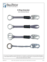
E. FALL CLEARANCE: Make certain enough clearance exists in your fall path
to prevent striking an object. The amount of clearance needed is dependent
upon the type of connecting subsystem used and anchorage location. See
Figure 6 for estimating fall clearance.
F. SHARP EDGES: Avoid working where parts of the system will be in contact
with, or abrade against, unprotected sharp edges.
G. RESCUE: The user must have a rescue plan
and the means at hand to implement it if a fall
occurs.
H. AFTER A FALL: Components which have been
subjected to the forces of arresting a fall must
be removed from service immediately and
destroyed.
I. GENERAL USE CONSIDERATIONS: Avoid
working where lifeline may cross or tangle
with that of another worker. Do not allow the
lanyard to pass under arms or between legs.
Do not clamp, tie, or other wise prevent the
rope grab lanyard connection handle from
moving freely into the “locked” position.
J. SLOPED ROOFS: Provisions must be made
(warning lines, monitors, guardrails) to prevent
swing falls from unprotected roof edges or
corners. The rope grab should be connected
Figure 5 - Swing Fall
Swing Fall Hazard
Figure 6 - Fall Clearance
Anchorage Connector
5/8 inch Synthetic Rope Lifeline
Working Level
Lower Level Counterweight
To determine fall clearance:
Estimate “A”, then read
clearance “B” from the chart
“A”in feet
“B”in feet
“A”
Rope length
to anchorage
“B”
Clearance required
to avoid hitting
lower level
12 ft. Minimum to
lower level
or obstruction

6
to the body support using a locking carabiner (direct connection) or a short lanyard. If a lanyard is used
for connecting to the rope grab, keep the length as short as possible, and never greater than 3 feet. The
lifeline must be protected from contact with sharp or abrasive edges and surfaces. The rope grab locking
operation must not be hindered by interference with the roof or objects on the roof surface.
K. UNSTABLE SURFACES: The rope grab is not suitable for use on unstable or slowly shifting materials,
such as sand or grain.
WARNING: Never connect more than one personal fall arrest or restraint system to a single lifeline or rope
grab.
WARNING: Follow manufacturer’s instructions for associated equipment used in your fall protection or restraint
system.
IMPORTANT: For custom versions of this product, follow the instructions herein. If included, see supplemental
instructions for additional information.
3.3 ATTACHING THE COBRA ROPE GRAB TO THE LIFELINE:
A. Ensure the rope grab is in the “UP” position as indicated on the product. The “UP” end of the rope grab
must be oriented towards the anchorage when installed onto the lifeline (see Figure 7). NOTE: Cobra
rope grabs incorporate a gravity-lock pin that slides out of the locking pin to prevent the lifeline sleeve
from mating with the rope grab cam when not held upright.
B. Push the opening lever (knurled knob) downward until it reaches the bottom of the groove. Press the
opening lever inward until the release button is completely depressed.
C. Pull the lifeline sleeve and the locking cam apart until the unit is fully opened.
D. To install on the lifeline, raise the locking cam to the “up” position and install the rope inside the lifeline
channel and close the rope grab halves (see Figure 8). The spring-loaded lock pin will snap the unit
shut.
E. The closing action should release the opening lever from the open position and the locking pin will slide
into the lock ring at the top of the lifeline sleeve. The opening lever should now be at the top of the
groove and at rest against the lifeline sleeve (see Figure 9).
F. Test the rope grab operation by pulling down on the locking cam. The rope grab must lock onto the
lifeline and prevent any descent on the lifeline once the cam is engaged.
3.4 POSITIONING THE ROPE GRAB ON THE LIFELINE:
A. Using the lanyard connected to the rope grab, pull up slightly on the rope grab locking cam to release
it from the locked position. Always keep a minimum of 3.7m (12 feet) of rope below the rope grab to
accommodate locking distance and fall clearance.
B. Using the connected lanyard, raise or lower the rope grab to the desired location. Apply tension to the
lifeline to assure smooth travel of the rope grab on the lifeline. Lifeline tension can be achieved by
adding a weight on the lifeline end or extending additional lifeline (in a hanging orientation) to provide
weight.
Figure 9 - Attaching to Lifeline
Sleeve Closed
Opening Lever
Returned To
“Up” Position
Release Button
Freed
Figure 7 - Attaching to Lifeline
Anchorage
Lifeline
Push
Opening
Lever
Down
Figure 8 - Attaching to Lifeline
Locking
Cam In “Up”
Position
Rope Installed
In Sleeve

7
C. After locating the rope grab, position it on the lifeline at or above the shoulders to reduce possible free
fall. Lock the rope grab at this position by pulling the locking cam until the cam lever is in the full down
position. The locking cam must be released before attempting to reposition the rope grab.
D. Under special conditions, such as working on a moving platform, it is allowable to let the rope grab
follow the worker as the platform is moved. The lanyard should be kept as short as possible and must
not exceed 3 feet (0.9m) in length (2 feet (0.6m) in Canada).
WARNING: Rope grab attachment and positioning instructions and procedures must be followed. Improper
assembly could allow the rope grab to slip or not lock onto the lifeline in the event of a fall and may result in
serious injury or death.
3.5 PARKING FEATURE:
A. To activate the parking feature, release the lever from the tab on the
side of the rope grab and allow it to rotate from vertical to horizontal
(see Figure 10).
B. The parking feature is now operational and will prevent the rope grab
from traveling down the lifeline. This allows the user to remain on the
lifeline for a period without the threat of the rope grab moving down the
lifeline when the user is active. The rope grab operates in manual mode
while the park feature is engaged.
C. To deactivate the parking feature, return the auto-locking lever to
upright, allowing the hole in the lever to catch on the tab on the side of
the rope grab vertical position and unlock from the lifeline by lifting up
on the locking cam.
3.6 ANTI-PANIC GRIP FEATURE: Select models of the Cobra Rope Grab have an anti-panic grip feature. In
the event of a fall, the user may grasp the rope grab in a manner that forces the locking cam into the open
position. The Cobra rope grabs with the anti-panic grip feature have an additional cam in the center of the
locking cam. This cam is pushed out and into the lifeline when the locking cam is forced beyond the open
position, thus stopping a fall in spite of the locking cam being held in the open position.
3.6 CONNECTING TO ANCHORAGE OR ANCHORAGE
CONNECTOR: When attaching the lifeline or lifeline
subsystem to the anchorage or anchorage connector,
ensure the connector (self-locking snap hook) is
fully engaged and locked onto the connection point.
Ensure connections are compatible in size, shape, and
strength. Refer to the anchorage connector and lifeline
manufacturer’s instructions for further information. See
Figure 11.
3.7 CONNECTING TO THE BODY SUPPORT: For fall arrest
applications, connect to the dorsal D-ring located between
the shoulders on the back of the full body harness.
For restraint applications, the dorsal or frontal harness
attachment may be used. If using a body belt for restraint
applications connect to the D-ring opposite the restraining
load. Ensure connections are compatible in size, shape,
and strength. Refer to the body support manufacturer’s
instructions for more information on making connections.
3.8 CONNECTING TO THE ROPE GRAB: When connecting an energy absorbing lanyard to the rope grab,
attach the lanyard end (vs. the energy absorber end) to the rope grab to reduce possible interference with
the operation of the rope grab by the energy absorber “pack”. Some rope grab models may be supplied
with a permanently attached lanyard or energy absorber. Do not attempt to attach additional lanyards
or connectors to these subsystems. If using a carabiner to connect directly to the rope grab, ensure the
carabiner will not interfere with the operation of the rope grab. Carabiners must be of the self-closing/self-
locking type. Ensure connections are compatible in size, shape, and strength. Ensure the connector attached
to the rope grab allows the handle to rotate freely, and does not interfere with the rope grab operation.
3.9 USE OF LIFELINES: (See Lifeline User Instruction Manual for complete details)
Figure 10 - Parking Feature
Auto-locking Lever
Figure 11 - Making Connections
Anchorage
Anchorage
Anchorage
Anchorage
Connector
Anchorage
Connector
Anchorage
Connector

8
• Always protect the lifeline if passing over or around sharp edges. Sharp edges can reduce rope strength
by 70% or more.
• Keep lifelines clean.
• Avoid twisting or kinking lifelines when coiling or uncoiling.
• Avoid using lifelines near acids or alkalines. If the lifeline is used around any chemical or compound,
watch for signs of deterioration.
• Never use a knotted lifeline, knots can reduce rope strength by 50%.
• Store lifelines properly. See section 6.0.
3.10 AFTER USE of the rope grab and its subsystem components, return it for cleaning or storage as described in
section 6.0.
4.0 TRAINING
4.1 TRAINING: The user, and the user’s employer, must be trained in the correct use and care of this
equipment. Both parties must be aware of the operating characteristics, application limits, and consequences
of improper use of this equipment.
IMPORTANT: Training must be conducted without exposing the trainee to a fall hazard. Training should be
repeated on a periodic basis.
5.0 INSPECTION
5.1 FREQUENCY:
A. Before Each Use, visually inspect the equipment per steps listed in section 5.2, 5.3, and 5.4.
B. The rope grab must be inspected by a competent person* other than the user at least annually. See
sections 5.2, 5.3, and 5.4 for guidelines. Record the results of each formal inspection in the inspection
log found in section 9.0. NOTE: Cal/OSHA requires personal fall arrest systems be inspected prior to
each use for wear, damage, and defects and inspected by a competent person* at least twice a year, in
accordance with the manufacturer’s recommendations, with inspection dates documented.
*Competent person: An individual knowledgeable of a manufacturer’s recommendations, instructions and
manufactured components who is capable of identifying existing and predictable hazards in the proper selection,
use and maintenance of fall protection.
IMPORTANT: If the rope grab has been subjected to fall arrest or impact forces, it must be immediately
removed from service and destroyed.
IMPORTANT: Extreme working conditions (harsh environments, prolonged use, etc.) may require increasing the
frequency of inspections.
5.2 INSPECTION STEPS FOR ROPE GRAB: See Figure 1.
Step 1. Inspect the attachment eye and locking cam to ensure that the cam moves freely without
hesitation, binding or sticking.
Step 2. Inspect the locking cam and ensure that the teeth are not rounded or worn.
Step 3. Inspect the locking cam lever spring and auto-locking lever springs. Ensure they are in the proper
location and undamaged.
Step 4. Inspect the spring for the locking pin (located in the groove) and ensure it is the proper location
and undamaged.
Step 5. Use the opening lever (knurled knob) to ensure that the locking pin travels freely up and down the
locking sleeve.
Step 6. Test repeatedly that the rope grab opens when the release button is depressed with the opening
lever. The release button must be fully extended after the rope grab is closed.
Step 7. The two halves of the rope grab must close and open freely on the hinge. Inspect the lifeline
channel and ensure that there are no dips or depressions worn into the channel and that the
dimples are without damage. Ensure all the labels and engravings are legible.

9
Step 8. Inspect the hinge, attachment eye, and the rest of the rope grab for signs of corrosion, wear,
cracks, distortion or other damage.
Step 9. With the rope grab open and upside-down, the gravity-lock pin should drop down and prevent the
rope grab from closing
Step 10. Activate the parking feature and verify that there is resistance against the locking cam when
attempting to raise the attachment eye. With the parking feature deactivated, there should be no
resistance on the locking cam.
Step 11. To test models equipped with the Panic Lock feature, install rope grab on lifeline. Pass the thumb
on one hand through the attachment eye and grasp the rope grab body with the rest of the hand.
Force the eye to open the locking lever until it stops. Run the rope grab down the lifeline and
ensure that it locks onto the lifeline.
Step 12. Record the inspection date and results in the inspection log in section 9.0.
5.3 INSPECTION STEPS FOR LIFELINE: (See the Lifeline User Instruction Manual for complete details)
Step 1. Lifeline hardware must not be damaged, broken, distorted, or have any sharp edges, burrs,
cracks, worn parts, or corrosion. Ensure the connecting hooks work properly. Hook gates must
move freely and lock upon closing.
Step 2. Inspect the rope for concentrated wear. The material must be free of frayed strands, broken yarns,
cuts, abrasions, burns, and discoloration. The rope must be free of knots, excessive soiling, heavy
paint buildup, and rust staining. Rope splices must be tight, with fi ve full tucks, and thimbles must
be held by the splice. Cracked or distorted rope thimbles may indicate that the lifeline has been
impact loaded. Check for chemical or heat damage (indicated by brown, discolored, or brittle
areas). Check for ultraviolet damage, indicated by discoloration and the presence of splinters and
slivers on the rope surface. All of the above factors are known to reduce rope strength. Damaged
or questionable ropes must be replaced.
Step 3. Inspect labels. All labels must be present and fully legible. Replace labels if illegible or missing
Step 4. Record the inspection date and results in the inspection log found in the Lifeline User Instruction
Manual.
5.4 If inspection reveals a defective condition, remove the unit from service immediately and destroy, or contact
a factory authorized service center for repair.
IMPORTANT: Do not attempt to alter, repair, or make substitutions to the rope grab or rope grab parts.
Equipment found to be in defective condition must be removed from service. Repairs may only be performed by
PROTECTA or those authorized in writing to do so.
6.0 MAINTENANCE
6.1 Clean the rope grab and lifeline with water and a mild soap solution. Wipe off hardware with a clean, dry
cloth, and hang to air dry. Do not force dry with heat. An excessive buildup of dirt, paint, etc. may prevent
the rope grab or lifeline from working properly, and in severe cases degrade the rope grab or rope to a point
where it has weakened and should be removed from service. If you have any questions concerning the
condition of the rope grab or lifeline, or have any doubt about putting them into service, contact PROTECTA.
See the Lifeline User Instruction Manual for specifi c maintenance details.
6.2 Additional maintenance and servicing procedures (replacement parts) must be completed by a factory
authorized service center. Authorization must be in writing. Do not attempt to disassemble the unit. See
section 5.1 for inspection frequency.
6.3 Store the rope grab and lifeline in a cool, dry, clean environment out of direct sunlight. Avoid areas where
chemical vapors may exist. Thoroughly inspect the rope grab and lifeline after any period of extended
storage.

10
7.0 SPECIFICATIONS / PERFORMANCE DATA
7.1 SPECIFICATIONS:
Material: All material used in construction is certifi ed to be new and free from defects.
Construction: Riveted and welded with hinged rope channel.
Material Type: Body, hinge, cam, and attachment eye – High impact resistant steel
Weight: 0.8 kgs (1.75 lbs)
Lifeline Diameter: 16mm (5/8 inch)
Parking Feature: Allows manual operation as required
Patent Number: U.S. 4,657,110, Can. 1,241,937, U.K. GB2,168,102B
7.2 PERFORMANCE DATA:
Maximum Arresting Distance: 1 meter (39 inch) when dynamically tested in accordance with CAN/
CSA Z259.2.1-98 or ANSI Z359.1
NOTE: This does not include lifeline elongation.
Arrest Force: Designed for 1,800 lbs. maximum arresting force
Maximum Capacity: 141 kg or 310 lbs.
Requirements: Meets applicable CAN/CSA Z259.2.1 and ANSI standards, including Z359.1, and applicable
OSHA standards, including 1910.66.
7.3 LIFELINE SPECIFICATIONS:
AC202C Cobra Marking
AC203C Cobra Label
AC202C Cobra Marking
8.0 LABELING
8.1 These labels and/or markings must be securely attached and fully legible:
ALL422 Series
DIA: 16mm (5/8”)
Material: polyester
Color: white
Construction: kernmantle
Min. break strength: 14,000 lbs (62.2 kNs)
Elongation: 1% @ 600lbF
2% @ 2200lbF
9% @ 11,000lbF
Certifi cation: CSA Z259.2.1
SSR100 Series
DIA: 16mm (5/8”)
Material: copolymer, polyester with Ultra Blue core
Color: blue
Construction: 3-strand
Min. break strength: 9,000 lbs (40 kNs)
Elongation: 1.6% @ 900lbF
3.5% @ 1800lbF
4.7% @ 3000lbF
Certifi cation: CSA Z259.2.1
RLL635 Series
DIA: 16mm (5/8”)
Material: coplymer
Color: white, green tracer
Construction: 3-strand
Min. break strength: 8,500 lbs (37.8 kNs)
Elongation: 2.0% @ 850lbF
3.2% @ 1700lbF
3.9% @ 2550lbF
Certifi cation: CSA Z259.2.1

11
INSPECTION DATE INSPECTION ITEMS
NOTED
CORRECTIVE ACTION MAINTENANCE
PERFORMED
Approved by:
Approved by:
Approved by:
Approved by:
Approved by:
Approved by:
Approved by:
Approved by:
Approved by:
Approved by:
Approved by:
Approved by:
Approved by:
Approved by:
Approved by:
Approved by:
Approved by:
Approved by:
Approved by:
9.0 INSPECTION AND MAINTENANCE LOG
DATE OF MANUFACTURE
MODEL NUMBER
DATE OF PURCHASE

12
A Capital Safety Company
USA Canada
3833 SALA Way 260 Export Boulevard
Red Wing, MN 55066-5005 Mississauga, Ontario L5S 1Y9
Toll Free: 800-328-6146 Toll Free: 800-387-7484
Phone: (651) 388-8282 Phone: (905) 795-9333
Fax: (651) 388-5065 Fax: (905) 795-8777
www.capitalsafety.com www.capitalsafety.com
This manual is available for download at www.capitalsafety.com.
Form: 5902254
Rev: C
I S O
9 0 0 1
Certificate No. FM 39709
This instruction applies to the following models:
AC202C
AC202D
AC202C-1SL
AC202C-2SL
AC202C-SA2
AC202C-SA3
AC203C-1SL
AC203C-2SL
AC203C-SA2
Additional model numbers may appear on the next printing of these instructions.
/