Page is loading ...

Crestron Electronics, Inc. Installation Guide - DOC. 7335A
15 Volvo Drive Rockleigh, NJ 07647 (2033019)
Tel: 888.CRESTRON 02.13
Fax: 201.767.7576 Specifications subject to
www.crestron.com change without notice.
Further Inquiries
To locate specific information or resolve questions after reviewing this guide, contact Crestron's True Blue Support at
1-888-CRESTRON [1-888-273-7876] or refer to the listing of Crestron worldwide offices on the Crestron Web site
(www.crestron.com/offices) for assistance within a particular geographic region.
To post a question about Crestron products, log onto the online help section of the Crestron Web site
(www.crestron.com/onlinehelp). First-time users must establish a user account to fully benefit from all available
features.
Future Updates
As Crestron improves functions, adds new features and extends the capabilities of the CLW-DELVEX-277-P,
additional information may be made available as manual updates. These updates are solely electronic and serve as
intermediary supplements prior to the release of a complete technical documentation revision.
Check the Crestron Web site periodically for manual update availability and its relevance. Updates are identified as
an “Addendum” in the Download column.
WARNING: To avoid fire, shock, or death; turn off power at circuit breaker or fuse and test that power is off before
wiring!
NOTES: Observe the following points.
• To be installed and/or used in accordance with appropriate electrical codes and regulations.
• This product should be installed by a qualified electrician.
PREPARING AND CONNECTING WIRES
Strip the ends of the wires approximately 1/4 in (6 mm). Use care to avoid nicking the conductors.
Crestron CLW-DELVEX-277-P
Wireless In-Wall Dimmer
Installation Guide
FCC ID: Contains EROCWD6790
Compliance Statement (Part 15.19 )
This device complies with Part 15 of the FCC Rules. Operation is subject to the following
two conditions:
1. This device may not cause harmful interference, and
2. This device must accept any interference received, including interference that may
cause undesired operation.
Warning (Part 15.21)
Changes or modifications not expressly approved by the party responsible for
compliance could void the user’s authority to operate the equipment.
RF Exposure (OET Bulletin 65)
To comply with FCC's RF exposure limits for general population / uncontrolled exposure,
this transmitter must be installed to provide a separation distance of at least 20 cm from
all persons and must not be co-located or operating in conjunction with any other
antenna or transmitter.
This product conforms to UL STD 1472; certified to CSA STD C22.2 No. 184.1.
DESCRIPTION
The CLW-DELVEX-277-P is a 500 W in-wall dimmer and programmable keypad designed to
operate as part of a complete Crestron
®
automation system communicating via the infiNET
EX
®
wireless control network. Without the need for additional control wiring, the
CLW-DELVEX-277-P easily replaces any standard in-wall dimmer or light switch. Although
functional as a standalone dimmer, the CLW-DELVEX-277-P delivers enhanced automation
and control capability when connected to any Crestron automation control system (or any
other Crestron control system) via the infiNET EX network.
Specifications
Specifications for the CLW-DELVEX-277-P are listed in the following table.
CLW-DELVEX-277-P Specifications
Important Notes
Read before installation.
• Codes: Install in accordance with all local and national electrical codes.
CAUTION: TO REDUCE THE RISK OF OVERHEATING AND POSSIBLE DAMAGE
TO OTHER EQUIPMENT, DO NOT INSTALL TO CONTROL A RECEPTACLE, A
MOTOR-OPERATED APPLIANCE OR TRANSFORMER-SUPPLIED APPLIANCE.
ATTENTION: GRADATEURS COMMANDANT UN BALLAST-AFIN DE RÉDUIRE
LE RISQUE DE SURCHAUFFE ET LA POSSIBILITÉ D’ENDOMMAGEMENT À
D’AUTRES MATÉRIELS, NE PAS INSTALLER POUR COMMANDER UNE PRISE,
UN APPAREIL OPÉRÉ DE MOTEUR OU UN APPAREIL ALIMENTÉ PAR UN
TRANSFORMATEUR.
• Wiring: Use copper wire only. For supply connections, use wire rated for at least 75° C.
• Lamp Type: For use with permanently installed incandescent, electronic low voltage,
tungsten-halogen, or dimmable CFL only.
• Electrical Boxes: Devices mount in standard electrical boxes. For easy installation,
Crestron recommends using 3 1/2 in (89 mm) deep electrical boxes. Several devices
can be installed in one electrical box (multigang). This requires derating of the dimming
device. For a smooth appearance, one-piece multigang faceplates (not supplied) can
be installed.
• Mechanical 3- or 4-way switches do not work with CLW-DELVEX-277-P dimmers.
• Spacing: If mounting one device above another, leave at least 4 1/2 in (115 mm)
vertical space between them.
• Low Voltage Applications: Use with electronic low voltage transformers only. Do not
use any magnetic low voltage transformers. Operation of a low voltage circuit with all
lamps inoperative or removed may result in current flow in excess of normal levels. To
avoid transformer overheating and premature transformer failure, Crestron
recommends the following:
> Do not operate low voltage circuits without operative lamps in place.
> Replace burned-out lamps as quickly as possible.
> Use transformers that incorporate thermal protection to prevent transformer failure
due to overcurrent.
Connection Wire Gauge Wire Color
HOT 16 AWG Black
NEU 16 AWG White
LOAD 16 AWG Red
GND 16 AWG Green
INSTALLATION
The following describes the installation of a CLW-DELVEX-277-P dimmer.
1. Turn power off at the circuit breaker.
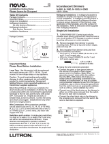
2. Wire the device as shown in the following diagram.
WARNING: Turn off power at the circuit breaker. Installing with power on can result in
serious personal injury and damage to the device.
CAUTION: New installations should be checked for short circuits prior to installing a
CLW-DELVEX-277-P dimmer. With power off, close the circuit and restore power. If the
lights do not work or a breaker trips, check and correct the wiring or fixture (if necessary).
Install the dimmer only when the short is no longer present. The warranty is void if the
dimmer is installed and operated with a shorted load.
White (NEU)
LOAD
Green
(GND)
Red (LOAD)
Black (HOT)
HOT
277V~
* The range is dependent on its placement and the building in which it is used. The construction of the building,
obstructions, and RF interference from other devices are factors determining the effective range of the unit.
3. Push all power wires back into the electrical box and fasten the device to the electrical
box with the provided screws.
4. Attach decorative faceplate.
5. Ensure all buttons, including the program button, actuate without sticking.
6. Restore power at the circuit breaker.
Multigang Installations
In multigang installations, several devices are grouped horizontally in one electrical box. For
a smooth appearance, one-piece multigang faceplates (not supplied) can be installed.
NOTE: When installing into a multigang box, do not fully tighten devices to box until
faceplate has been aligned.
The load capacity for each device in the electrical box must be derated. Refer to the
following diagrams for derating information.
Derating Information for CLW-DELVEX-277-P Dimmers
500 W 400 W 400 W 400 W 250 W 400 W
Changing Button Assemblies
The button assembly can be removed and replaced with other button assemblies. To
change the button assembly:
1. As shown in the following diagram, remove the button assembly by squeezing the
sides of the bezel near the bezel snaps.
Squeeze At Arrow
Points And Pull To
Remove Button
Assembly
NOTE: When the button assembly is removed, power to the unit and load is
removed automatically.
2. Remove button(s) from the front of the button assembly as shown in the following
diagram.
3. Insert new buttons through the front of the bezel and snap into place as shown in the
following diagram. Ensure that the LED strip is on the left side.
4. Attach button assembly to the device as shown in the following diagram. Ensure that
LED strip is on the left side.
Gently Spread
Frame Apart To
Remove Buttons
Gently Spread
Frame Apart To
Insert Buttons
5. Once power has been restored, press and hold the right side of the air-gap switch
(program button) as shown in the following diagram. After 5 seconds some LEDs start
flashing. Continue to hold the button and proceed to step 6.
6. While holding the program button, tap all of the buttons in the new layout. The LED
next to the tapped button lights.
NOTE: If the rocker switch is installed, press the top and bottom of the rocker.
7. After all of the buttons have been tapped, release the program button to save the
settings.
NOTE: Changing the button configuration alters the device’s behavior. Refer to
"Default Button Functions" on the following page for details.
Press
And Hold
Program
Button
Tap Each
Installed
Button
6
5
Release To
Save Settings
7
SPECIFICATION DETAILS
Power Requirements 277 Vac
Load Types Incandescent, Tungsten-Halogen, Electronic Low
Voltage transformers for low voltage Halogen or LED,
electronic CFL
Load Ratings
Minimum Load
Maximum Load
10 W
500 W (Refer to the derating chart in the “Multigang
Installations” section on this page.)
Environmental
Temperature
Humidity
32º F to 104ºF (0º C to 40º C)
10 to 90% Relative Humidity (Non-Condensing)
Dimensions
Height
Width
Depth
4 1/8 in (105 mm)
1 3/4 in (45 mm)
1 13/16 in (47 mm)
Weight 5 oz (128 g)
Operating Frequency 2400 to 2483.6 MHz (802.15.4 compliant)
Operating Ranges*
Device to Gateway
Device to Device
150 ft (45 m) indoors; 250 ft (76 m) outdoors
100 ft (30 m) indoors; 175 ft (53 m) outdoors
Default RF ID 01

TROUBLESHOOTING
The following table provides corrective action for possible trouble situations. If further
assistance is required, please contact a Crestron customer service representative.
WIRELESS COMMUNICATIONS
The device connects to the Crestron network via the infiNET EX communications protocol.
Use the procedures outlined below to join or leave an infiNET EX network and to verify
communications between the device and the control system.
Joining an infiNET EX Network
Before a device can be used in a lighting system, it must first join an infiNET EX network by
being acquired by an infiNET EX gateway.
NOTE: A device can be acquired by only one gateway.
1. Put the infiNET EX gateway into Acquire mode from the unit itself or from Crestron
Toolbox™, as described in the latest version of its manual, which is available from the
Crestron Web site (www.crestron.com/manuals).
NOTE: In an environment where multiple gateways are installed, only one gateway
should be in Acquire mode at any time.
2. Place the device into Acquire mode by doing the following:
a. Tap the top button three times then press and hold it down (tap-tap-tap-press+hold)
until all LEDs on the device flash once (this can take up to 10 seconds).
b. Release the button to start the acquire process. The top LED blinks slowly to show
that the device is actively scanning the infiNET EX network.
• The device is acquired when the top LED stops blinking.
• The top LED blinks fast to indicate that the device was not successfully acquired
to the infiNET EX network. Tap the setup button to acknowledge failure to
acquire to the infiNET EX network. Ensure gateway is in Acquire mode and within
range before attempting the acquire process again.
Leaving an infiNET EX Network
To leave an infiNET EX network put the device into Acquire mode, as described in “Joining
an infiNET EX Network” above, when no gateway is in Acquire mode.
Verifying Communications Status
To check the communication status of the device tap the setup button three times then press
and hold it down (tap-tap-tap-press+hold) for 2 seconds. The top two LEDs turn on or blink to
indicate the communication status. Refer to the following table for details.
Off
Preset 1
Toggle
Raise
Lower
Preset 1
Preset 1
Preset 1
Off
Preset 1
Toggle
Raise
Lower
Preset 1
Off
Off
Preset 1
Preset 2
Full On
Fast Off
Full On
Full On
Full On
Full On
Fast Off
Full On
Full On
Fast Off
Fast Off
Full On
Full On
Raise
Lower
Raise
Lower
Raise
Lower
Raise
Lower
Raise
Lower
Lower
Raise
Button HOLD (Hold More Than 0.5 Seconds)
Button TAP
Button DOUBLE TAP (Tap Twice Within 0.5 Seconds)
Default Button Functions
The figures below illustrate the default functions available for each physical button
configuration and tap/hold actuation sequence.
Preset 1
OPERATION
Basic Operation
NOTE: The device may be warm to the touch during operation. This is normal.
The CLW-DELVEX-277-P is shipped with a rocker switch already installed. In this
configuration, the unit functions as shown below.
NOTE: Operation described in this guide assumes the CLW-DELVEX-277-P is operating
in Local mode (without the use of a control system). The device can also operate in
Remote mode, where button behavior is dictated entirely by the control system program.
Power to dimmer and load can be disconnected by pushing on the air-gap switch as
shown in the following diagram.
Disconnecting Power
NOTE: Power is automatically disconnected when the button assembly is removed. For
instructions on removing the button assembly, refer to “Changing Button Assemblies” on
the previous page.
Setting Preset Levels
The CLW-DELVEX-277-P can recall and store up to three presets depending on the
installed button configuration.
To set a preset level:
1. Adjust the light level to the desired level.
2. Enter Programming mode by quickly tapping the right side of the air-gap switch
(program button) as shown below. Buttons that are capable of storing a preset flash
their LED.
3. Press and hold the desired preset button until the LED blinks (approximately 2
seconds). Release the button to store the new level.
If a button is not pressed, the device exits the Programming mode after approximately 5
seconds.
NOTE: Programming mode is disabled when the load is off.
LEDs Indicate Load Level.
When All Loads Are Off,
Top LED Remains Lit
Dimly To Act As Night
Light
Tap To Turn On
Press And Hold
To Raise Light Level
Tap To Turn Off
Press And Hold
To Lower Light Level
Push Here to
Open Air-Gap
NOTE: A delayed off can be added via control system programming.
Preset 1
Preset 2
Preset 3
Off
Quickly Tap
Program Button
LEDs
Flash
2
1
3
Hold Button
To Store New
Level
TROUBLE POSSIBLE CAUSE(S) CORRECTIVE ACTION
Device does not
function.
Dimmer is not
receiving line power.
Verify that dimmer is properly
connected to power line HOT and
NEU and that circuit breaker is
closed.
Device is in Remote
mode.
Check the program to determine /
change the operating mode.
Dimmer powers
up but load
does not turn
on.
Lamps are burned
out.
Check lamp.
Open circuit. Check wiring.
Short circuit exists
on dimmer output
and protection circuit
has activated.
Check wiring.
Dimmer cycles
off and on.
Thermal overload
condition.
Check that total load is within limits.
Return and Warranty Policies
Merchandise Returns / Repair Service
1. No merchandise may be returned for credit, exchange or service without prior authorization
from Crestron. To obtain warranty service for Crestron products, contact an authorized
Crestron dealer. Only authorized Crestron dealers may contact the factory and request an
RMA (Return Merchandise Authorization) number. Enclose a note specifying the nature of
the problem, name and phone number of contact person, RMA number and return address.
2. Products may be returned for credit, exchange or service with a Crestron Return
Merchandise Authorization (RMA) number. Authorized returns must be shipped freight
prepaid to Crestron, 6 Volvo Drive, Rockleigh, N.J. or its authorized subsidiaries, with RMA
number clearly marked on the outside of all cartons. Shipments arriving freight collect or
without an RMA number shall be subject to refusal. Crestron reserves the right in its sole
and absolute discretion to charge a 15% restocking fee plus shipping costs on any products
returned with an RMA.
3. Return freight charges following repair of items under warranty shall be paid by Crestron,
shipping by standard ground carrier. In the event repairs are found to be non-warranty,
return freight costs shall be paid by the purchaser.
Crestron Limited Warranty
Crestron Electronics, Inc. warrants its products to be free from manufacturing defects in materials
and workmanship under normal use for a period of three (3) years from the date of purchase from
Crestron, with the following exceptions: disk drives and any other moving or rotating mechanical
parts, pan/tilt heads and power supplies are covered for a period of one (1) year; touch screen
display and overlay components are covered for 90 days; batteries and incandescent lamps are not
covered.
This warranty extends to products purchased directly from Crestron or an authorized Crestron
dealer. Purchasers should inquire of the dealer regarding the nature and extent of the dealer's
warranty, if any.
Crestron shall not be liable to honor the terms of this warranty if the product has been used in any
application other than that for which it was intended or if it has been subjected to misuse, accidental
damage, modification or improper installation procedures. Furthermore, this warranty does not cover
any product that has had the serial number altered, defaced or removed.
This warranty shall be the sole and exclusive remedy to the original purchaser. In no event shall
Crestron be liable for incidental or consequential damages of any kind (property or economic
damages inclusive) arising from the sale or use of this equipment. Crestron is not liable for any
claim made by a third party or made by the purchaser for a third party.
Crestron shall, at its option, repair or replace any product found defective, without charge for parts
or labor. Repaired or replaced equipment and parts supplied under this warranty shall be covered
only by the unexpired portion of the warranty.
Except as expressly set forth in this warranty, Crestron makes no other warranties, expressed or
implied, nor authorizes any other party to offer any warranty, including any implied warranties of
merchantability or fitness for a particular purpose. Any implied warranties that may be imposed by
law are limited to the terms of this limited warranty. This warranty statement supersedes all previous
warranties.
The specific patents that cover Crestron products are listed at patents.crestron.com.
Crestron, the Crestron logo, Crestron Toolbox and infiNET EX are either trademarks or registered
trademarks of Crestron Electronics, Inc. in the United States and/or other countries. Other trademarks,
registered trademarks and trade names may be used in this document to refer to either the entities
claiming the marks and names or their products. Crestron disclaims any proprietary interest in the
marks and names of others. Crestron is not responsible for errors in typography or photography.
This document was written by the Technical Publications department at Crestron.
©2013 Crestron Electronics, Inc.
/