FATEK FBs Series User manual
- Category
- Digital & analog I/O modules
- Type
- User manual

FBs-PLC User’s Manual【Hardware】
Contents
Chapter 1:Introduction of FATEK FBs Series PLC
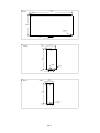
1.1 Appearance of Main Unit ................................................................................................................. H1-1
1.2 Appearance of Expansion Unit/Module .......................................................................................... H1-2
1.3 Appearance of Communication Expansion Module ..................................................................... H1-4
1.4 List of FBs-PLC Models ................................................................................................................... H1-5
1.5 Specifications of Main Unit ............................................................................................................... H1-8
1.6 Environmental Specifications .......................................................................................................... H1-9
1.7 Connection Diagrams of Various Models ...................................................................................... H1-10
1.7.1 NC Control Main Unit (MN) ........................................................................................................................... H1-10
1.7.2 Basic/Advanced Main Unit (MA/MC) ........................................................................................................... H1-11
1.7.3 Digital I/O Expansion Unit .............................................................................................................................. H1-13
1.7.4 Digital I/O Expansion Module ........................................................................................................................ H1-14
1.7.5 High-Density Digital I/O Expansion Module ................................................................................................ H1-15
1.7.6 Numeric I/O Expansion Module .................................................................................................................... H1-15
1.7.7 Analog I/O Expansion Module ...................................................................................................................... H1-15
1.7.8 Temperature Input Module ............................................................................................................................ H1-16
1.7.9 AI/AO/Temperature Combo Module .......................................................................................................... H1-17
1.7.10 Expansion Power Module ......................................................................................................................... H1-17
1.7.11 Voice Output Module ................................................................................................................................... H1-17
1.7.12 Potential Meter Module .............................................................................................................................. H1-17
1.7.13 Load Cell Module ....................................................................................................................................... H1-17
1.7.14 Communication Module (CM) .................................................................................................................... H1-18
1.7.15 Communication Board (CB) ........................................................................................................................ H1-19
1.7.16 Analog Expansion Board ........................................................................................................................... H1-20
1.7.17 Simple HMI .................................................................................................................................................... H1-20
1.8 Drawings with External Dimensions ............................................................................................... H1-21
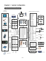
Chapter 2:System Configuration
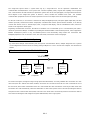
2.1 Single-Unit System of FBs-PLC ...................................................................................................... H2-1

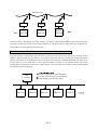
2.2 Formation of Multi-Unit System ....................................................................................................... H2-2
2.2.1 Connection of Multiple FBs-PLC (CPU Link) .............................................................................................. H2-2
2.2.2 Connection of FBs-PLC with Host Computer or Intelligent Peripherals ................................................... H2-3
Chapter 3:Expansion of FBs-PLC
3.1 I/O Expansion ................................................................................................................................... H3-1
3.1.1 Digital I/O Expansion and I/O Numbering .................................................................................................... H3-1
3.1.2 Numeric I/O Expansion and I/O Channel Mapping .................................................................................... H3-3
3.2 Expansion of Communication Port ................................................................................................. H3-5
Chapter 4:Installation Guide
4.1 Installation Environment ................................................................................................................... H4-1
4.2 PLC Installation Precautions ........................................................................................................... H4-1
4.2.1 Placement of PLC .......................................................................................................................................... H4-1
4.2.2 Ventilation Space ............................................................................................................................................ H4-2
4.3 Fixation by DIN RAIL ........................................................................................................................ H4-3
4.4 Fixation by Screws ........................................................................................................................... H4-4
4.5 Precautions on Construction and Wiring ........................................................................................ H4-6
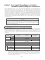
Chapter 5:Power Supply Wiring, Power Consumption Calculation, and
Power Sequence Requirements
5.1 Specifications and Wiring of AC Power Sourced Power Supply ................................................. H5-1
5.2 Specifications and Wiring of DC Power Sourced Power Supply ................................................. H5-2
5.3 Residual Capacity of Main/Expansion Unit and Current Consumption of Expansion Module
……… ........................................................................................................................................................ H5-4
5.3.1 Residual Capacity of Main/Expansion Unit ................................................................................................. H5-4
5.3.2 Maximum Current Consumption of Expansion Module ............................................................................ H5-5
5.3.3 Calculation Example of Power Capacity .................................................................................................... H5-7
5.4 Requirement of Power Sequence in Main Unit and Expansion Unit/Module ........................... H5-9
Chapter 6:Digital Input (DI) Circuit
6.1 Specifications of Digital Input (DI) Circuit ........................................................................................ H6-1
6.2 Structure and Wiring of 5VDC Ultra High Speed Differential Input Circuit .................................. H6-2
6.3 24VDC Single-End Input Circuit and Wiring for SINK/SOURCE Input ....................................... H6-3

Chapter 7:Digital Output (DO) Circuit
7.1 Specifications of Digital Output Circuit ............................................................................................ H7-2
7.2 5VDC Ultra High Speed Line-Driver Differential Output Circuit and its Wiring ........................... H7-3
7.3 Single-End Output Circuit ................................................................................................................ H7-3
7.3.1 Structure and Wiring of Single-End Relay Output Circuit .......................................................................... H7-3
7.3.2 Structure and Wiring of Single-End Transistor SINK & SOURCE Output Circuit ................................... H7-4
7.4 Speed up the Single-End Transistor Output Circuit (only applicable to high and medium-speed)
......................................................................................................................................................... H7-6
7.5 Output Device Protection and Noise Suppression in DO Circuit ............................................... H7-6
7.5.1 Protection of Relay Contacts and Noise Suppression ............................................................................... H7-6
7.5.2 Protection of Transistor Output and Noise Suppression ............................................................................ H7-8
Chapter 8:Test Run, Monitoring and Maintenance
8.1 Inspection After Wiring and Before First Time Power on .............................................................. H8-1
8.2 Test Run and Monitoring ................................................................................................................. H8-1
8.3 LED Indications on PLC Main Unit and Troubleshooting ............................................................. H8-2
8.4 Maintenance ..................................................................................................................................... H8-4
8.5 The Charge of Battery & Recycle of Used Battery ........................................................................ H8-4

H1-1
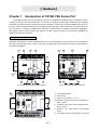
Chapter 1 Introduction of FATEK FBS Series PLC
The FATEK FBS Series PLC is a new generation of micro PLC equipped with excellent functions comparable to medium
or large PLC, with up to five communication ports. The maximum I/O numbers are 256 points for Digital Input (DI) and Digital
Output (DO), 64 words for Numeric Input (NI) and Numeric Output (NO). The Main Units of FB
S are available in three types: MA
(Economy Type), MC (High-Performance Type), and MN (High-Speed NC Type). With the combination of I/O point ranges from
10 to 60, a total of 17 models are available. Fifteen DI/DO and 19 NI/NO models are available for Expansion Units/Modules.
With interface options in RS232, RS485, USB, Ethernet, CANopen, Zigbee and GSM, the communication peripherals are
available with 15 boards and modules.
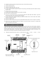
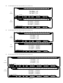
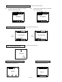
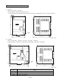
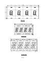
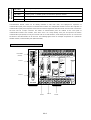
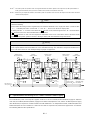
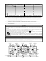
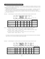
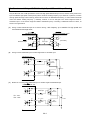
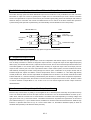
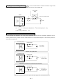
1.1 Appearance of Main Unit
All the Main Units of FBS-PLC have the same physical structure. The only difference is the case width. There are four different
case sizes, which are 60mm, 90mm, 130mm, and 175mm. The figure below will use the Main Unit case of the FBS-24MC as
an example for illustration:
( )
OUT Y
Y6Y1
AC100~240V
C0
Y0
Y4
Y2
C2 Y3
PORT0
Y5
C4 C6
0
4
8
2I
65
9
Y8
Y7 Y9
3
7
( )
IN X
X8
X0
PROGRAMMABLE
CONTROLLER
24V OUT
S/S
RXTX
RUN
ERR
I2 I3
POW
X4X2
X1 X3
0
8
4
2I
I0
9
65
X6
X5 X7
X12
3
I I
7
X10
X9
X11 X13
X10
3I20
Y2
AC100~240V
C0
Y1
Y0
C2
8
Y4
Y3 C4
Y5 Y6
C6 Y7
9
5647
X2
TX
24V OUT
S/S
X0
X1
IN X
( )
RX
ERR
OUT Y
( )
POW
RUN
0
X3 X5
X4
X7
X6
X9
X8
Y8
Y9
X12
X11 X13
3
1
4
11
6
12
9
16
15
18
20
19
15
10
17
3
5
2
8
7
( 未裝通訊板之正視圖 )
( 蓋板掀開之正視圖 )
98
45
I
I2 I3
I
II0
67
32
max.
400mA
IN
400mA
max.
IN
FBs-24MCR2-AC
FBs-24MCR2-AC
13
14
X9
Y7
PORT1
Y0
PORT2
AC100~240V
C0
24V OUT
RX
TX
RX
S/S
TX
RX
Y4
PORT0
C2
Y1
Y3
Y2
CONTROLLER
TX
6574
9
C4
Y5
8
C6
Y6
POW
ERR
I
RUN
0
( )
OUT Y
23
PROGRAMMABLE
X4X0
X1 X3
X2
I3
I
5
9
4
I2
8
X5
0
X6
76
IN X
( )
I0
I
I
X8
2
X7
3
Y9
Y8
X12X10
X11 X13
400mA
max.
IN
FBs-24MCR2-AC
【 Hardware】
○
1
35mm-width DIN RAIL
○
2
DIN RAIL tab
○
3
Hole for screw fixation (ψ4.5×2)
○
4
Terminals of 24VDC power input and digital input
(Pitch 7.62mm)
○
5
Terminals of main power input and digital output
(Pitch 7.62mm)
○
6
Standard cover plate (without communication
board)
○
7
Cover plate of built-in communication port (Port 0)
(Front view without Communication Board)
(Front view with cover plate removed)
(Front view with CB-22 Board installed)

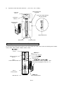
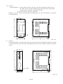
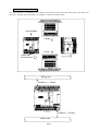
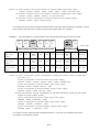
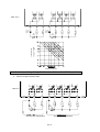
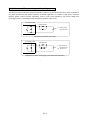
H1-2
Output expansion slot
Digital output terminal block and
Main power input (for XY- )
Screw hole
ψ4.5 × 2
Expansion cable
connector
Y9
DIN RAIL tab
C3C1
Y1
Y2
CONTROLLER
PROGRAMMABLE
7658
Y3
Y4
Y5
C5
Y7
Y6
C7
I09
Y8
OUT Y
2I34
( )
POW
Output status indicator
Y10
X11
Digital input
terminal block
X1
24V IN
S/S X2
X7 X9X5X3
I3
X4 X6
6758
IN X
I4
I0
9 I I
( )
I2
2I3
X8
4
X10
X13
X12 X14
Input status
indicator
FBs-24XYR
Output expansion slot
cover plate
Front view of output expansion slot with
cover plate removed
○
8
Indicators for transmit (TX) and receive (RX) status of built-in communication port (Port0).
○
9
Indicator for Digital Input (Xn).
○
10
Indicator for Digital Output (Yn).
○
11
Indicator for system status (POW, RUN, ERR).
○
12
I/O output expansion header cover [units of 20 points or beyond only], with esthetic purpose and capable of securing
expansion cable.
○
13
FBS-CB22 Communication Board (CB).
○
14
FBS-CB22 CB cover plate (each CB has its own specific cover plate)
○
15
Screw holes of communication board.
○
16
Connector for communication board (for 7 types CB of CB2, CB22, CB5, CB55, CB25, CBE, CBCAN , 3 types AIO
of B2DA, B2AD, B4AD, and 2 types DAP of BDAP and BPEP)
○
17
Left side (communication) expansion header (only available in MC/MN model, for CM22, CM25, CM55, CM25E,
CM55E, and CMGSM connection).
○
18
Connector for Memory Pack.
○
19
Connector for built-in communication port (Port 0) (With USB and RS232 optional, shown in the figure is for RS232)
○
20
Right side (I/O) output expansion header (only available in units with 20 points or beyond), for connecting with
cables from expansion units/modules.
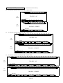
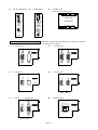
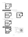
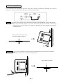
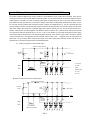
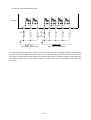
1.2 Appearance of Expansion Unit/Module
There are three types of cases for expansion units/modules. One type uses the same case as main unit that of the 90mm,
130mm, and 175mm, while the other two have thinner 40mm and 60mm cases, which are for expansion modules. All
expansion cables (left) of expansion units/modules are flat ribbon cables (5cm long), which were soldered directly on the PCB,
and the expansion header (right) is a 14Pin Header, with this to connect the right adjacent expansion units/modules. In the
following, each of the three types of expansion units/modules is described as an example:
z Expansion unit/module with 90mm, 130mm, or 175mm width case: [ -24XY
◇–◎, -40XY◇–◎, -60XY◇–◎, -16TC,
-16RTD]

H1-3
z Expansion unit/module with 60mm width case: [-16XY◇, -16Y◇, -20X ]
Expansion cable
connector
DIN RAIL tab
I/O terminal block
Screw hole
ψ4.5 × 2
Output expansion slot
Output status
indicator
8
3
C1
Y1
Y2
Y3
C3
Y4
POW
67
2I
Y8Y6
Y5
C5
Y7
( )
OUT Y
45
8
3
I/O terminal block
S/S
2
I
7
6
X1
X2
X3
X8
54
( )
IN X
X6X4
X5
X7
Output expansion slot
Front view of output expansion slot
with cover plate removed
FBs-16XYR
Output expansion
slot cover plate
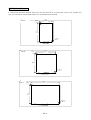
z Expansion module with 40mm width case: [ -8XY◇, -8Y◇, -8X, -6AD, -2DA, -4DA, -4A2D, -2A4TC,
-2A4RTD,-7SG1, -7SG2, -2TC, -6TC, -6RTD, -CM5H, -6NTC, -4PT,
-1LC, -1HLC, -VOM ]
Screw hole
ψ4.5 × 2
Expansion cable
connector
Output status
indicator
Input status
indicator
DIN RAIL tab
I/O terminal block
POW
OUT Y
C1
Y1
I
2
Y3
C3
Y2
Y4
( )
43
X2
2I
S/S
X1
X4
4
3
( )
IN X
X3
I/O terminal block
Front view of output expansion slot
with cover plate removed
FBs-8XYR
Output expansion slot
cover plate
Output expansion slot

H1-4
DIN RAIL tab
Screw hole
ψ4.5 × 2
Expansion cable
connector
Input status
indicator
X8
FG
I/O Header socket
X24
X16
S/S3
X22
X20
X18
X10
S/S2
X14
X12
FG
FG
X19
X21
X23
X17
X13
X15
X9
X11
S/S1
X6
X4
X2
20
I8 I9I7
POW
I0
2
9
I
I II2
34
X1
X5
X7
X3
23
24
222I
IN X
( )
I5I4I3
657
I6
8
FBs-24X
Output expansion slot
cover plate
Front view of output expansion
slot with cover plate
Output expansion slot
z Expansion module with 40mm width case: [ -24X, -24YT, -24YJ, -32DGI ]
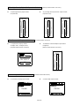
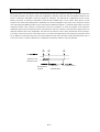
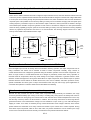
1.3 Appearance of Communication Expansion Module
The Communication Module (CM) of FBS-PLC has a 25mm-width case, which can be used in the following seven modules:
-CM22, -CM25, -CM55, -CM25E, -CM55E, -CM25C, -CM5R.
螺絲固定孔
ψ4.5 × 2
通訊模組擴充扁平排線接頭
(插於主機之通訊模組連接插座 )
Port3 通訊指示燈
Port4
通訊插座
Port3
通訊插座
Port4 通訊指示燈
17
DIN RAIL卡鉤
FBs-CM25E
PORT3 (RS232)
RX
TX
NT
TX
TX
RX
RX
RUN
LNK
乙太網路
(Port4)
Terminator 附加開關
(T:ON, N:OFF)
G
6
2
1
+
3
ETHERNET
PORT4 (RS485)
Port 3
Communication
Screw hole
φ
4.5
×
2
Port3 Communication
Port 4
Communication Socket
Port4
Communication indicato
r
Terminator Switch
(
T: ON
,
N:OFF
)
DIN RAIL tab
Communication module expansion cable
connector (to be plugged in main unit
○
17
)
Ethernet network
(Port 4)

H1-5
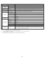
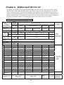
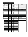
1.4 List of FBs-PLC Models
Module Name Specifications
Main Units
Basic
Main Units
FBs-10MA◇∆–◎–C
6 points 24VDC digital input (2 points high speed 100KHz, 2 points medium speed 20KHz, 2 points
medium speed total 5KHz); 4 points relay or transistor output (2 points high speed 100KHz, 2 points
medium speed 20KHz); 1 RS232 or USB port(expandable up to 3); I/O is not expandable
FBs-14MA◇∆–◎–C
8 points 24VDC digital input (2 points high speed 100KHz, 2 points medium speed 20KHz, 4 points
medium speed total 5KHz); 6 points relay or transistor output (2 point high speed 100KHz, 4 points
medium speed 20KHz); 1 RS232 or USB port(expandable up to 3); I/O is not expandable
FBs-20MA◇∆–◎–C
12 points 24VDC digital input (2 points high speed 100KHz, 4 points medium speed 20KHz, 6 points
medium speed total 5KHz); 8 points relay or transistor output (2 points high speed 100KHz, 6 points
medium speed 20KHz); 1 RS232 or USB port(expandable up to 3)
FBs-24MA◇∆–◎–C
14 points 24VDC digital input (2 points high speed 100KHz, 6 points medium speed 20KHz, 6 points
medium speed total 5KHz); 10 points relay or transistor output (2 points high speed 100KHz, 6 points
medium speed 20KHz); 1 RS232 or USB port(expandable up to 3)
FBs-32MA◇∆–◎–C
FBs-32MB◇∆–◎–C
20 points 24VDC digital input (2 points high speed 100KHz, 6 points medium speed 20KHz, 8 points
medium speed total 5KHz); 12 points relay or transistor output (2 points high speed 100KHz, 6 points
medium speed 20KHz); 1 RS232 or USB port(expandable up to 3); (MB is detachable terminal block)
FBs-40MA◇∆–◎–C
FBs-40MB◇∆–◎–C
24 points 24VDC digital input (2 points high speed 100KHz, 6 points medium speed 20KHz, 8 points
medium speed total 5KHz); 16 points relay or transistor output (2 points high speed 100KHz, 6 points
medium speed 20KHz); 1 RS232 or USB port(expandable up to 3); (MB is detachable terminal block)
FBs-60MA◇∆–◎–C
FBs-60MB◇∆–◎–C
36 points 24VDC digital input (2 points high speed 100KHz, 6 points medium speed 20KHz, 8 points
medium speed total 5KHz); 24 points relay or transistor output (2 points high speed 100KHz, 6 points
medium speed 20KHz); 1 RS232 or USB port(expandable up to 3); (MB is detachable terminal block)
Advanced
Main Units
FBs-10MC◇∆–◎
6 points 24VDC digital input (2 points high speed 200KHz, 2 points medium speed 20KHz, 2 points
medium speed total 5KHz); 4 points relay or transistor output (2 points high speed 200KHz, 2 points
medium speed 20KHz); 1 RS232 or USB port (expandable up to 5); built-in RTC; I/O is not expandable
FBs-14MC◇∆–◎
8 points 24VDC digital input (2 points high speed 200KHz, 2 points medium speed 20KHz, 4 points
medium speed total 5KHz); 6 points relay or transistor output (2 points high speed 200KHz, 4 points
medium speed 20KHz); 1 RS232 or USB port (expandable up to 5); built-in RTC; I/O is not expandable
FBs-20MC◇∆–◎
12 points 24VDC digital input (4 points high speed 200KHz, 2 points medium speed 20KHz, 6 points
medium speed total 5KHz); 8 points relay or transistor output (4 points high speed 200KHz, 4 points
medium speed 20KHz); 1 RS232 or USB port (expandable up to 5); built-in RTC; detachable terminal block
FBs-24MC◇∆–◎
14 points 24VDC digital input (4 points high speed 200KHz, 4 points medium speed 20KHz, 6 points
medium speed total 5KHz); 10 points relay or transistor output (4 points high speed 200KHz, 4 points
medium sped 20KHz); 1 RS232 or USB port (expandable up to 5); built-in RTC; detachable terminal block
FBs-32MC◇∆–◎
20 points 24VDC digital input (6 points high speed 200KHz, 2 points medium speed 20KHz, 8 points
medium speed total 5KHz); 12 points relay or transistor output (6 points high speed 200KHz, 2 points
medium speed 20KHz); 1 RS232 or USB port (expandable up to 5); built-in RTC; detachable terminal block
FBs-40MC◇∆–◎
24 points 24VDC digital input (6 points high speed 200KHz, 2 points medium speed 20KHz, 8 points
medium speed total 5KHz); 16 points relay or transistor output (6 points high speed 200KHz, 2 points
medium speed 20KHz); 1 RS232 or USB port (expandable up to 5); built-in RTC; detachable terminal block
FBs-60MC◇∆–◎
36 points 24VDC digital input (8 points high speed 200KHz, 8 points medium speed total 5KHz); 24 points
relay or transistor output (8 points high speed 200KHz); 1 RS232 or USB port (expandable up to 5);
built-in RTC; detachable terminal block
NC Positioning
Main Units
FBs-20MN◇∆–◎
2 sets (1 axis) 920KHz 5VDC digital differential input, 10 points 24VDC digital input (4 points high speed
200KHz, 6 points medium speed total 5KHz); 2 sets (1 axis) 920KHz 5VDC digital differential output, 6
points relay or transistor output (average high speed 200KHz); 1 RS232 or USB port (expandable up to 5);
built-in RTC; detachable terminal block
FBs-32MN◇∆–◎
4 sets (2 axes) 920KHz 5VDC digital differential input, 16 points 24VDC digital input (4 points high speed
200KHz, 8 points medium speed total 5KHz); 4 sets (2 axes) 920KHz 5VDC digital differential output, 8
points relay or transistor output (4 points high speed 200KHz); 1 RS232 or USB port (expandable up to 5);
built-in RTC; detachable terminal block
FBs-44MN◇∆–◎
8 sets (4 axes) 920KHz 5VDC digital differential input, 20 points 24VDC digital input (8 points medium
speed total 5KHz); 8 sets (4 axes) 920KHz 5VDC digital differential output, 8 points relay or low speed
transistor output; 1 RS232 or USB port (expandable up to 5); built-in RTC; detachable terminal block
Right Side Expansion Modules
Expansion Power
Supply
FBs-EPW–AC/D24
Power supply of 100~240VAC or 24VDC input for expansion module; 3 sets output power with 5VDC,
24VDC, and 24VDC, 14W capacity
DIO
Expansion Units
FBs-24XY◇–◎
14 points 24VDC digital input, 10 points relay or transistor output, built-in power supply
FBs-40XY◇–◎
24 points 24VDC digital input, 16 points relay or transistor output, built-in power supply
FBs-60XY◇–◎
36 points 24VDC digital input, 24 points relay or transistor output, built-in power supply
DIO Expansion
Modules
FBs-8X
8 points 24 VDC digital input
FBs-8Y◇
8 points relay or transistor output
FBs-8XY◇
4 points 24VDC digital input, 4 points relay or transistor output
FBs-16Y◇
16 points relay or transistor output
FBs-16XY◇
8 points 24VDC digital input, 8 points relay or transistor output
FBs-20X
20 points 24VDC digital input
FBs-24XY◇
14 points 24VDC digital input, 10 points relay or transistor output
FBs-40XY◇
24 points 24VDC digital input, 16 points relay or transistor output
FBs-60XY◇
36 points 24VDD digital input, 24 points relay or transistor output
FBs-24X
24 points high-density 24VDC digital input, 30 pins header with latch
FBs-24YT/J
24 points high-density transistor SINK(T) or SOURCE(J) output (0.1A max.),30 pins header with latch

H1-6
Module Name Specifications
Thumbwheel switch
module
FBs-32DGI
8 sets 4 digits (total 32 digits) thumbwheel switch (or 128 points independent switch) multiplex input
module, 30 pins header connector
16/7 Segment LED
display modules
FBs-7SG1
1 set 8 digits 7-segment/4 digits 16-segment LED display (or 64 points independent LED) output display
module, 16 pins header connector
FBs-7SG2
2 sets 8 digits 7-segment/4 digits 16-segment LED display (or 128 points independent LED) output
display module, 16 pins header connector
AIO modules
FBs-2DA
2 channels, 14-bit analog output module (-10~10V, 0~10V or -20~20mA, 0~20mA)
FBs-4DA
4 channels, 14-bit analog output module (-10~10V, 0~10V or -20~20mA, 0~20mA)
FBs-4A2D
4 channels, 14-bit analog input (same specification as 6AD)+2 channels, 14-bit analog output (same
specification as 2DA) combo module
FBs-6AD
6 channels, 14-bit analog input module (-10~10V, 0~10V or -20~20mA, 0~20mA)
Temperature
measurement
modules
FBs-2TC
2 channels, thermocouple temperature input module with 0.1°C resolution.
FBs-6TC
6 channels, thermocouple temperature input module with 0.1°C resolution.
FBs-16TC
16 channels, thermocouple temperature input module with 0.1°C resolution.
FBs-6RTD
6 channels, RTD temperature input module with 0.1°C resolution.
FBs-16RTD
16 channels, RTD temperature input module with 0.1°C resolution.
FBs-6NTC
6 channels, NTC temperature input module with 0.1°C resolution.
AI + Temperature
Measurement
combo modules
FBs-2A4TC
2 channels, 14-bit analog input (same specifications as 6AD)+ 4 channels thermocouple temperature
input (same specifications as 6TC) combo module
FBs-2A4RTD
2 channels, 14-bit analog input (same specifications as 6AD) + 4 channels RTD temperature input (same
s
pecifications as 6RTD) combo module
Voice modules FBs-VOM
Built-in 1MB memory (play continuously up to 2 minutes), extendable 4GB SD card(play continuously up
t
o 8,000 minutes) voice module, 245 messages, output 2W
Load Cell Module FBs-1LC
1 channel, load cell measurement module with 16-bit resolution (including sign bit)
Potential Meter
Module
FBs-4PT
4
channels, 14-bit potential meter input module (Impedance range: 1~10K Ω)
Left Side Expansion Modules
Communication
modules
FBs-CM22
2 ports RS232 (Port3 +Port 4) communication module
FBs-CM55
2 ports RS485 (Port3 +Port 4) communication module
FBs-CM25
1 port RS232 (Port3) + 1 port RS485 (port 4) communication module
FBs-CM25E
1 port RS232 (Port3) + 1 port RS485 (port 4) + Ethernet network interface communication module
FBs-CM55E
1 port RS485 (Port3) + 1 port RS485 (port 4) + Ethernet network interface communication module
FBs-CMZB
Z
igBee communication module
FBs-CMZBR
Z
igBee communication repeate
r
FBs-CMGSM
GSM wireless communication module
FBs-CM25C
General purpose RS232 to RS485/RS422 communication interface converter with photocouple isolation
FBs-CM5R
General purpose RS485 repeater with photocouple isolation
FBs-CM5H
General purpose 4 ports RS485 HUB with photocouple isolation, RS485 can be connected as star
connection
Communication
boards
FBs-CB2
1 port RS232 (Port 2) communication board
FBs-CB22
2 ports RS232 (Port 1+ Port 2) communication board
FBs-CB5
1 port RS485 (Port 2) communication board
FBs-CB55
2 ports RS485 (Port 1+ Port 2) communication board
FBs-CB25
1 port RS232 (Port 1) + 1 port RS485 (Port 2) communication board
FBs-CBE
1 port 10 Base T Ethernet communication board
FBs-CBEH
1 port 100 Base T Ethernet communication board
FBs-CBCAN
1 port CANopen communication board
AIO
boards
FBs-B2DA
2 channels, 12-bit analog output board (0~10V or 0~20mA)
FBs-B2A1D
2 channels, 12-bit analog input + 1 channel, 12-bit analog output combo analog board (0~10V or
0~20mA)
FBs-B4AD
4
channels, 12-bit analog input board (0~10V or 0~20mA)
Precision Load
Cell Module
FBs-1HLC
1 channel, high precision weighing control module with 24-bit resolution
3-Axis Motion
Control Module
FBs-30GM
3-Axis with linear and circular interpolation advanced motional control module, 3 sets of 200KHz high
s
peed pulse input, 3 sets of 500KHz high speed pulse output, 14 points main unit, 16M Bytes program
capacity, 20K Words retentive file register, built-in RS485 and Ethernet, 7.62mm detachable terminal
block
Simple HMI
FBs-BDAP
Board type Data Access Panel
FBs-BPEP
Board type Parameter Entry Panel
FBs-PEP/PEPR
Multi characters with graphics-based Parameter Entry Panel, built-in RFID Read/Write module with PEPR
FBs-DAP-B/BR
16 X 2 LCD character display, 20 keys keyboard, 24VDC power supply, RS485 communication interface,
built-in RFID Read/Write module with BR
FBs-DAP-C/CR
16 X 2 LCD character display, 20 keys keyboard, 5VDC power supply, RS232 communication interface,
built-in RFID Read/Write module with CR

H1-7
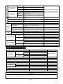
Module Name Specifications
Peripheral and Accessory
RFID Card CARD-H
Read / Write wireless card (for FBs-DAP-BR/CR and FBs-PEPR)
Programming
Devices
FP-08
FBs- Series PLC handheld programmer
Winproladder
FATEK-PLC Winproladder Programming software
Memory Pack FBs-PACK
FBs-PLC program memory pack with 20K Words program, 20K Words register, write protection switch
PWMDA module PWMDA
10-bit single channel pulse width modulation(PWM) 0~10V analog output (AO) module
USB- RS232
Converter Cable
FBs-U2C-MD-180
Communication converter cable with standard USB AM connector to RS232 MD4M connector (used in
standard PC USB to FBs main unit Port 0 RS232), length 180cm
Communication
cables
FBs-232P0-9F-150
MD4M to DB9F communication cable (FBs main unit Port 0 RS232 connect to standard DB9M), length
150cm
FBs-232P0-9M-400
MD4M to DB9M communication cable (FBs main unit Port 0 RS232 connect to DB9F), length 400cm
FBs-232P0-MD-200
MD4M to MD4M communication cable (FBs main unit Port 0 RS232 connect to FBs-PEP/PEPR), length
200cm
FBs-232P0-MDR-200
MD4M to 90˚ MD4M communication cable (FBs main unit Port 0 RS232 connect to FBs-PEP/PEPR),
length 200cm
High density DIO
cable
HD30-22AWG-200
High density modules(FBs-24X, FBs-24YT/J, FBs-32DGI) connector,30pin Socket, 22AWG I/O cable,
length200cm
16/7-Segment
LED display
DBAN.8-nR
0.8” 4-digit 16-segment LED display, n means R(Red) 16-segment LED characters display installed,
can be 1~4
DBAN.2.3-nR
2.3” 4-digit 16-segment LED display, n means R(Red) 16-segment LED characters display installed,
can be 1~4
DB.56-nR
0.56" 8-digit 7-segment display, n means R(Red) 7-segment LED characters display installed,
can be 1~8
DB.8-nR
0.8" 8-digit 7-segment display, n means R(Red) 7-segment LED characters display installed, can be 1~8
DB2.3-nR
2.3" 8-digit 7-segment display, n means R(Red) 7-segment LED characters display installed, can be 1~8
DB4.0-nR
4.0" 4-digit 7-segment display, n means R(Red) 7-segment LED characters display installed, can be 1~4
Training Box
FBs-TBOX
46cm x 32 cm x 16cm suitcase, containing FBs-24MCT main unit. FBs-CM25E communication module
(RS232 + RS485 + Ethernet network), 14 simulated input switches, 10 external relay output, Doctor
terminal outlet I/O, peripherals such as stepping motor, encoder, 7-segment display, 10 of 10mm LED
indicator, thumbwheel switch, and 16 key keyboard.
1. ◇:R ─ Relay output;T ─ Transistor SINK(NPN) output; J ─ Transistor SOURCE (PNP) output
2. ∆:2 ─ built-in RS232 port;U ─ built-in USB port (non-standard)
3. ◎:AC ─ 100~240VAC power supply; D12 ─ 12VDC power supply;D24 ─ 24VDC power supply
4. –C:Blank ─ Standard;–C ─ add in RTC
5. The unmarked frequencies of Digital Input (DI) or Digital Output (DO) are low speed.

H1-8
1.5 Specifications of Main Unit
Item Specification Note
Execution Speed 0.33uS/per Sequence Command
Space of Control Program 20K Words
Program Memory FLASH ROM or SRAM+Lithium battery for Back-up
Sequence Command 36
Application Command 326 (126 types) Include Derived Commands
Flow Chart (SFC) Command 4
Single Point BIT Status
X Output Contact(DI) X0~X255 (256)
Corresponding to External Digital Input
Point
Y Output Relay(DO) Y0~Y255 (256)
Corresponding to External Digital Output
Point
TR Temporary Relay TR0~TR39 (40)
M
Internal Relay
Non-retentive
M0~M799 (800)*
Can be configured as retentive type
M1400~M1911 (512)
Retentive M800~M1399 (600)* Can be configured as non-retentive type
Special Relay M1912~M2001 (90)
S Step Relay
Non-retentive S0~S499 (500)*
S20~S499 can be configured as
retentive type
Retentive S500~S999 (500)* Can be configured as non-retentive type
T Timer ”Time Up” Status Contact T0~T255 (256)
C Counter ”Count Up” Status Contact C0~C255 (256)
Register WORD Data
TMR
Current
Time
Value
Register
0.01S Time base T0~T49 (50)*
T0 ~ T255 Numbers for each time base
can be flexibly adjusted.
0.1S Time base T50~T199 (150)*
1STime base T200~T255 (56)*
CTR
Current
Counter
Value
Register
Retentive C0~C139 (140)* Can be configured as non-retentive type
Non-retentive C140~C199 (60)* Can be configured as retentive type
32-Bit
Retentive C200~C239 (40)* Can be configured as non-retentive type
Non-retentive C240~C255 (16)* Can be configured as retentive type
HR
DR
Data Register
Retentive
R0~R2999 (3000)* Can be configured as non-retentive type
D0~D3999 (4000)
Non-retentive R3000~R3839 (840)* Can be configured as retentive type
HR
ROR
Retentive R5000~R8071 (3072)*
When not configured as ROR, it can
serve as normal register (for read/Write)
Read-only
Register
R5000~R8071 can be configured as ROR,
default setting is (0)*
ROR is stored in special ROR area and
not consume program space
File Register F0~F8191 (8192)*
Must save/retrieved via special
commands
IR Input register R3840~R3903 (64) Corresponding to external numeric input
OR Output Register R3904~R3967 (64)
Corresponding to external numeric
output
SR Special System Register R3968~R4167 (197) R4000~R4095 (96)
Special Register
0.1mSHigh Speed Timer register R4152~R4154 (3)
High Speed
Counter
Register
Hardware(4 sets) DR4096~DR4110 (4×4)
Software (4 sets) DR4112~DR4126 (4×4)
Real Time Calendar Register
(Not available in MA model)
R4128 (sec) R4128 (min) R4130 (hour) R4131 (day)
Optional for MA module
R4132
(month)
R4133 (year) R4134 (week)
XR Index Register V、Z (2), P0~P9 (10)
Interrupt
Control
External Interrupt Control 32 (16 point input positive/negative edges)
Internal Interrupt Control 8 (1, 2 3, 4, 5, 10, 50, 100mS)
0.1mS High Speed Timer (HST) 1 (16bits), 4 (32bits, derived from HHSC)
16-Bit

H1-9
High Speed Counter
Hardware High Speed
Counter
(HHSC) /32 bits
Channels Up to 4
y Total number of HHSC and SHSC is
8.
y HHSC can change into High Speed
Timer with 32 bits/0.1mS Time base.
Counting
mode
8 (U/D, U/D×2, K/R K/R×2, A/B, A/B×2, A/B×3
A/B×4)
Counting
frequency
Up to 200KHz (single-end input) or 920KHz
(differential input)
Software High Speed
Counter
(SHSC) /32 bits
Channels Up to 4
Counting
mode
3 (U/D、K/R、A/B)
Counting
frequency
Maximum sum up to 5KHz
Communication
Interface
Port0 (RS232 or USB)
Communication Speed 4.8Kbps~921.6Kbps
(9.6Kbps)*
Port1~Port4
(RS232, RS485 or Ethernet)
Communication Speed 4.8Kbps~921.6Kbps
(9.6Kbps)*
Port1~4 talk FATEK or Modbus RTU
Master/Slave Communication Protocol
Maximum Connections 254
NC
Positioning
Output
(PSO)
Number of Axes Up to 4
Output Frequency
200KHz single output (single) 100KHZ ( A/B way)
920KHz(single way) and 460KHz(A/B way)
differential output.
Output Pulse Mode 3 (U/D、K/R、A/B)
Positioning Language Special Positioning Programming Language
HSPWM
Output
Number of Points Up to 4
Output Frequency
72Hz~18.432KHz (with 0.1﹪resolution)
720Hz~184.32KHz ( with 1﹪resolution)
Captured input
Points
Max.36 points (all of main units have the feature)
> 10μS(super high speed/high speed input)
Captured pulse
width
> 47μS(medium speed input)
> 470μS(mid/low speed input)
Setting of Digital Filter
X0~X15
Frequency 14KHz ~ 1.8MHz Chosen by frequency at high frequencies
Tine constant 0 ~ 1.5mS
/
0 ~ 15mS,adjustable by step
of 0.1mS/1mS
Chosen by time constant at low frequencies
X16~X35 Time constant 1mS~15mS,adjustable by step of 1mS
Maximum expandable module 32
1.6 Environmental Specifications
Item Specification Note
Operating Ambient
Temperature
Enclosure
equipment
Minimum
5°C
Permanent Installation
Maximum
40°C
Open
equipment
Minimum
5°C
Maximum
55°C
Storage Temperature
-25°C~+70°C
Relative Humidity (non-condensing, RH-2)
5%~95%
Pollution Level
Degree II
Corrosion Resistance
By IEC-68 Standard
Altitude
2000m≦
Vibration
Fixed by DIN RAIL
0.5G, for 2 hours each along the 3 axes
Secured by screws
2G, for 2 hours each along the 3 axes
Shock
10G, 3 times each along the 3 axes
Noise Suppression
1500Vp-p, width 1us
Withstand Voltage
1500VAC, 1 minute
L, N to any terminal
Warning
The listed environmental specifications are for FBS-PLC under normal operation. Any operation in environment
not conform to above conditions should be consulted with FATEK.

H1-10
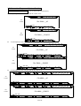
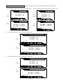
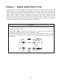
1.7 Connection Diagrams of Various Models
[7.62mm Detachable Terminal Block]
z 20 point digital I/O main unit (12 points IN, 8 points OUT)
Y6Y4Y2Y1-Y0-
SG0
Y0+ Y1+
C2
Y3
Y5
Y7
X10
AC100~240V
X2X0+
24V OUT
S/S
X1+
X0- X1-
X4
X3
X5
X6
X7
X8
X9
X11
400mA
max.
IN
FBS-20MN◇△-AC
Y6Y4Y2Y1-Y0-
SG0
Y0+ Y1+
C2
Y3
Y5
Y7
X10
X2X0+
24V OUT
S/S
X1+
X0- X1-
X4
X3 X5
X6
X7
X8
X9
X11
FBS-20MN◇△-D24/D12
max.
400mA
IN
24VDC / 12VDC
z 32 point digital I/O main unit (20 points IN, 12 points OUT)
X0-
Y1+
Y0-
Y0+
AC100~240V
S/S
24V OUT
X0+
Y8 Y10Y6Y4Y3-Y2-Y1-
Y2+
SG0
Y3+
C4
Y5
Y7
C8
Y9 Y11
X1-
X1+ X2
X4-
X4+
X3
X5
+ X6
X5-
X8
X7
X9
X10
X11
X12 X16
X13
X14
X15
X18
X17 X19
max.
400mA
IN
FBS-32MN◇△-AC
X0-
Y1+
Y0-
Y0+
S/S
24V OUT
X0+
Y8 Y10Y6Y4Y3-Y2-Y1-
Y2+
SG0
Y3+
C4
Y5
Y7
C8
Y9 Y11
X1-
X1+ X2
X4-
X4+
X3
X5
+ X6
X5-
X8
X7 X9
X10
X11
X12 X16
X13
X14
X15
X18
X17 X19
FBS-32MN◇△-D24/D12
max.
400mA
IN
24VDC/ 12VDC
z 44 point digital I/O main unit (28 points IN, 16 points OUT)
X19
Y11
Y10Y8Y6- Y7-Y4- Y5-Y3-Y2-Y0- Y1-
Y4+Y0+ Y1+
SG0
Y3+Y2+ Y7+
SG4
Y5+ Y6+
C8
Y9
X7
AC100~240V
X1-
24V OUT
S/S
X0-
X0+ X1+
X4-
X2
X3
X4+
X5-
X5+
X6
X12-X9-X8-
X8+ X9+
X11
X10
X12+
X15
X13-
X13+
X14
X17
X16 X18
Y14Y12
Y13
C12
Y15
X27X23X21
X20 X22
X25
X24 X26
max.
400mA
IN
FBS-44MN◇△-AC
X19
Y11
Y10Y8Y6- Y7-Y4- Y5-Y3-Y2-Y0- Y1-
Y4+Y0+ Y1+
SG0
Y3+Y2+
Y7+
SG4
Y5+
Y6+
C8
Y9
X7X1-
24V OUT
S/S
X0-
X0+ X1+
X4-
X2
X3
X4+
X5-
X5+ X6
X12-X9-X8-
X8+ X9+
X11
X10
X12+
X15
X13-
X13+
X14
X17
X16 X18
Y14Y12
Y13
C12
Y15
X27X23X21
X20 X22
X25
X24 X26
FBS-44MN◇△-D24/D12
max.
400mA
IN
24VDC / 12VDC
1.7.1 NC Control Main Unit
AC
Power
DC
Power
AC
Power
AC
Power
DC
Power
DC
Power

H1-11
[7.62mm Terminal Block, fixed in model MA, detachable in models MB/MC]
z 10 point digital I/O main unit (6 points IN, 4 points OUT) z 14 point digital I/O main unit (8 points IN, 6 points OUT)
AC
Power
DC
Power
S/S
24V OUT
C0
AC100~240V
C2
Y0
Y1
Y3
Y2
X5X1
X0
X3
X2 X4
IN
400mA
max.
FBS-10MA◇△-AC
FB
S-10MC◇△-AC
S/S
24V OUT
C0
C2
Y0
Y1
Y3
Y2
X5X1
X0
X3
X2 X4
FBS-10MA◇△-D24/D12
FB
S-10MC◇△-D24/D12
IN
400mA
max.
24VDC / 12VDC
AC
Power
DC
Power
C2
AC100~240V
C0
Y0
Y1
Y5Y3
Y2 Y4
X1
24V OUT
S/S
X0
X5
X3
X2 X4
X7
X6
IN
400mA
max.
FBS-14MA◇△-AC
FB
S-14MC◇△-AC
C2C0
Y0
Y1
Y5
Y3
Y2 Y4
X1
24V OUT
S/S
X0
X5X3
X2 X4
X7
X6
FBS-14MA◇△-D24/D12
FB
S-14MC◇△-D24/D12
IN
400mA
max.
24VDC / 12VDC
z 20 point digital I/O main unit (12 points IN, 8 points OUT)
AC
Power
DC
Power
AC100~240V
C0
Y1
Y0
Y2
C2
Y4
Y3
Y6Y5
C4 C6
Y7
24V OUT
S/S
X0 X2
X1
X4
X3
X8X6
X5
X7
X10
X9
X11
IN
400mA
max.
FBS-20MA◇△-AC
FB
S-20MC◇△-AC
C0
Y1
Y0
Y2
C2
Y4
Y3
Y6Y5
C4 C6
Y7
24V OUT
S/S
X0 X2
X1
X4
X3
X8X6
X5
X7
X10
X9
X11
FBS-20MA◇△-D24/D12
FB
S-20MC◇△-D24/D12
IN
400mA
max.
24VDC / 12VDC
z 24 point digital I/O main unit (14 points IN, 10 points OUT)
AC
Power
DC
Power
Y6Y1
AC100~240V
C0
Y0
Y4
Y2
C2
Y3
Y5
C4 C6
Y8
Y7 Y9
X8X0
24V OUT
S/S
X4X2
X1 X3
X6
X5 X7
X12X10
X9
X11 X13
IN
400mA
max.
FBS-24MA◇△-AC
FB
S-24MC◇△-AC
Y6Y1
C0
Y0
Y4
Y2
C2
Y3
Y5
C4 C6
Y8
Y7 Y9
X8X0
24V OUT
S/S
X4X2
X1 X3
X6
X5 X7
X12X10
X9
X11 X13
FBS-24MA◇△-D24/D12
FB
S-24MC◇△-D24/D12
IN
max.
400mA
24VDC/ 12VDC
1.7.2 Basic/Advanced Main Unit

H1-12
z 32 point digital I/O main unit (20 points IN, 12 points OUT)
AC
Power
DC
Power
Y8
AC100~240V
Y4Y1
C0
Y0
Y2
C2
Y3
Y6
Y5
C4 C6
Y7
C8
Y10
Y9 Y11
24V OUT
X12
X4X0
S/S
X2
X1 X3
X8X6
X5 X7
X10
X9
X11
X16X14
X13 X15
X18
X17 X19
IN
400mA
max.
FBS-32MA◇△-AC
FB
S-32MB◇△-AC
FB
S-32MC◇△-AC
Y8Y4Y1
C0
Y0
Y2
C2
Y3
Y6Y5
C4 C6
Y7
C8
Y10
Y9 Y11
24V OUT X12
X4X0
S/S
X2
X1 X3
X8X6
X5 X7
X10
X9
X11
X16X14
X13 X15
X18
X17 X19
FBS-32MA◇△-D24/D12
FB
S-32MB◇△-D24/D12
FB
S-32MC◇△-D24/D12
IN
400mA
max.
24VDC/ 12VDC
z 40 point digital I/O main unit (24 points IN, 16 points OUT)
AC
Power
DC
Power
X21
Y15
C4
AC100~240V
C0 C2
Y0
Y1
Y3
Y2 Y4
Y9
Y7
C6
Y5 Y6
C8
Y8
C12
Y11
Y10
Y13
Y12 Y14
X5
24V OUT
S/S
X1
X0
X3
X2 X4
X13
X9
X7
X6 X8
X11
X10 X12
X17X15
X14 X16
X19
X18
X20
X23
X22
IN
400mA
max.
FBS-40MA◇△-AC
FB
S-40MB◇△-AC
FB
S-40MC◇△-AC
X21
Y15
C4C0 C2
Y0
Y1
Y3
Y2 Y4
Y9
Y7
C6
Y5
Y6
C8
Y8
C12
Y11
Y10
Y13
Y12 Y14
X5
24V OUT
S/S
X1
X0
X3
X2 X4
X13
X9X7
X6 X8
X11
X10 X12
X17X15
X14 X16
X19
X18
X20
X23
X22
FBS-40MA◇△-D24/D12
FB
S-40MB◇△-D24/D12
FB
S-40MC◇△-D24/D12
IN
400mA
max.
24VDC / 12VDC
z 60 point digital I/O main unit (36 points IN, 24 points OUT)
AC
Power
DC
Power
24V OUT X28X12
Y8
Y4Y1
Y0
C0
AC100~240V
C2 Y3
Y2
Y6
C4 C6
Y5
C8
Y7
X4X0
S/S
X2
X1 X3
X8X6
X5 X7
X10
X9
X11
Y14
Y11Y9
Y10
Y13C12
Y12 Y16
C16Y15 Y17 Y19
Y18
X20X16X14
X13 X15
X18
X17 X19
X24X22
X21 X23
X26
X25 X27
Y21C20
Y20
Y23
Y22
X32X30
X29 X31
X34
X33 X35
IN
400mA
max.
FBS-60MA◇△-AC
FB
S-60MB◇△-AC
FB
S-60MC◇△-AC
24V OUT X28X12
Y8
Y4Y1
Y0
C0 C2
Y3
Y2
Y6
C4 C6
Y5
C8
Y7
X4X0
S/S
X2
X1 X3
X8X6
X5 X7
X10
X9
X11
Y14
Y11Y9
Y10
Y13
C12
Y12 Y16
C16
Y15 Y17 Y19
Y18
X20X16X14
X13 X15
X18
X17 X19
X24X22
X21 X23
X26
X25 X27
Y21
C20
Y20
Y23
Y22
X32X30
X29 X31
X34
X33 X35
FBS-60MA◇△-D24/D12
FB
S-60MB◇△-D24/D12
FB
S-60MC◇△-D24/D12
IN
400mA
max.
24VDC / 12VDC

H1-13
[7.62mm fixed terminal block]
z 24 point I/O expansion unit (14 points IN, 10 points OUT)
AC
Power
DC
Power
AC100~240V
C1 C3
Y4
C5
Y1
Y3Y2
Y5
S/S
24V OUT
X3X1
X2
X5
X4
X6
Y10
C7
Y8
Y6 Y7 Y9
X10
X8
X7
X9
X12
X11 X13
X14
IN
400mA
max.
FBS-24XY◇-AC
C1 C3
Y4
C5
Y1
Y3
Y2 Y5
S/S
24V OUT
X3X1
X2
X5
X4
X6
Y10
C7
Y8
Y6
Y7
Y9
X10
X8
X7 X9
X12
X11 X13
X14
FBS-24XY◇-D24/D12
IN
400mA
max.
24VDC / 12VDC
z 40 point I/O expansion unit (24 points IN, 16 points OUT)
AC
Power
DC
Power
X12
C1
AC100~240V
Y5Y2
Y1
Y3
C3
Y4
C7
C5
Y6
Y8
Y7
S/S
24V OUT X5X1
X4X2
X3
X8X6
X7
X10
X9
X11
Y11Y9
C9
Y10 Y12
C13
Y16
Y14
Y13 Y15
X19X15
X14
X13
X16 X18
X17
X22X20
X21
X24
X23
IN
400mA
max.
FBS-40XY◇-AC
X12
C1
Y5Y2
Y1
Y3
C3
Y4
C7
C5
Y6
Y8
Y7
S/S
24V OUT
X5X1
X4X2
X3
X8X6
X7
X10
X9
X11
Y11Y9
C9
Y10 Y12
C13
Y16Y14
Y13 Y15
X19X15
X14
X13
X16 X18
X17
X22X20
X21
X24
X23
FBS-40XY◇-D24/D12
IN
400mA
max.
24VDC / 12VDC
z 60 point I/O expansion unit (36 points IN, 24 points OUT)
AC
Power
DC
Power
X20
Y14
C5
AC100~240V
C1
Y3
Y2
Y1
C3
Y4
Y5
Y9
Y8
C7
Y6
Y7
C9
Y11
Y10 Y12
C13
Y13
24V OUT
S/S
X3X1
X2
X5
X4 X6
X10
X9X7
X8
X11 X13
X12
X17X15
X14 X16
X19
X18
Y24
Y19
Y16
Y15 Y17
C17
Y18
C21
Y20 Y22
Y21 Y23
X34
X27
X24
X23X21
X22
X25
X26
X31
X29
X28 X30
X33
X32
X35
X36
IN
400mA
max.
FBS-60XY◇-AC
X20
Y14
C5C1
Y3
Y2
Y1
C3
Y4
Y5
Y9
Y8
C7
Y6
Y7
C9
Y11
Y10 Y12
C13
Y13
24V OUT
S/S
X3X1
X2
X5
X4 X6 X10
X9X7
X8
X11 X13
X12
X17X15
X14
X16
X19
X18
Y24
Y19
Y16
Y15 Y17
C17
Y18
C21
Y20 Y22
Y21 Y23
X34
X27
X24
X23X21
X22
X25
X26
X31
X29
X28 X30
X33
X32
X35
X36
FBS-60XY◇-D24/D12
IN
400mA
max.
24VDC / 12VDC
1.7.3 Digital I/O Expansion Unit

H1-14
[7.62mm fixed terminal block]
z 8 point digital I/O module (4 points IN, 4 points OUT)
X4
C3C1
Y1 Y2
S/S
X2
X1 X3
Y4
Y3
FBS-8XY◇
z 8 point digital input module (8 points IN )
X6
X5
X8
X7
S/S
X4X2
X1 X3
FBS-8X
z 8 point digital output module (8 points OUT)
C5
Y5
Y6
Y7
C7
Y8
Y1
C1
Y2 Y3
C3
Y4
FBS-8Y◇
z 16 point digital I/O module (8 points IN, 8 points OUT)
C1
Y1
Y2
C3
Y3
C5
Y4
Y6
Y5
Y8
Y7
S/S
X2
X1
X4
X3
X6
X5
X8
X7
FBS-16XY◇
z 20 point digital input module (20 points IN)
X1
X13X11
X12
S/S
X17X15
X14 X16
X19
X18 X20
X9X5X3
X2 X4
X7
X6 X8
X10
FBS-20X
z 16 point digital output module (16 points OUT)
Y10
C9
Y9
C11
Y11
Y12
Y15
Y13
C13
Y14
Y16
Y1
C1
Y2
C3
Y3
Y6
C5
Y4
Y5 Y7
Y8
FBS-16Y◇
z 24 point digital I/O module (14 points IN, 10 points OUT)
Y1
C1
Y2
C7C5
Y4
C3
Y3
Y5 Y6
Y7
S/S
X1
X2
X3
X4
X5
X6
X7
X8
X9
Y10
Y8
Y9
X10
X11
X12
X13
X14
FBS-24XY◇
z 40 point digital I/O module (24 points IN, 16 points OUT)
X20
Y14
C5C1
Y3
Y2
Y1
C3
Y4
Y5
Y9
Y8
C7
Y6 Y7
C9
Y11
Y10 Y12
C13
Y13
S/S
X3
X2
X1
X6X4
X5 X13
X10
X8
X7
X9
X12
X11 X17
X14 X16
X15
X18
X19
Y16
Y15
X24X22
X21 X23
FBS-40XY◇
z 60 point digital I/O module (36 points IN, 24 points OUT)
Y14
C5C1
Y3
Y2
Y1
C3
Y4
Y5
Y9
Y8
C7
Y6
Y7
C9
Y11
Y10
Y12
C13
Y13
Y24
Y19
Y16
Y15 Y17
C17
Y18
C21
Y20 Y22
Y21 Y23
X20
S/S
X3X1
X2
X5
X4 X6
X10
X8
X7 X9
X12
X11 X13 X17X15
X14 X16
X19
X18 X34
X27
X24X22
X21 X23 X25
X26
X31
X29
X28 X30 X32
X33
X36
X35
FBS-60XY◇
1.7.4 Digital I/O Expansion Module

H1-15
[30Pin/2.54mm Header connector]
z 24 point high-density input module
(24 points IN)
I
2
S/S1
X2
X4
X6
X8
S/S2
X10
X12
X14
X16
S/S3
X18
X20
X22
X24
30
29
X1
X3
X5
X7
FG
X9
X11
X13
X15
FG
X17
X19
X21
X23
FG
FBS-24X
z 24 point high-density transistor output module
(24 points OUT)
I
2
V1+
Y2
Y4
Y6
Y8
V2+
Y10
Y12
Y14
Y16
V3+
Y18
Y20
Y22
Y24
30
29
Y1
Y3
Y5
Y7
V1-
Y9
Y11
Y13
Y15
V2-
Y17
Y19
Y21
Y23
V3-
FBS-24YT
I
2
V1+
Y2
Y4
Y6
Y8
V2+
Y10
Y12
Y14
Y16
V3+
Y18
Y20
Y22
Y24
30
29
Y1
Y3
Y5
Y7
V1-
Y9
Y11
Y13
Y15
V2-
Y17
Y19
Y21
Y23
V3-
FBS-24YJ
[2.54mm Header connector]
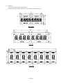
z 7 segment LED display module
(8 digits/-7SG1, 16 digits/-7SG2)
[16 pin/2.54mm Header connector]
CH1
CH0
FBS-7SG1 / 2
z Thumbwheel switch multiplex input module
(4 digits
×8)
[30Pin/2.54mm Header connector]
FBS-32DGI
24V+
NC
S2
S4
S6
S8
D1
D3
D5
D7
D9
D11
D13
D15
NC
FG
24V-
S1
S3
S5
S7
D0
D2
D4
D6
D8
D10
D12
D14
NC
I
2
30
29
[7.62mm fixed terminal block]
z 6 channel A/D analog input module
I2-
I2+
I4-
I4+
I3+
I3-
I5+
I5-
BV I U 10V5V
I0-AG
I0+
I1-
I1+
FBS-6AD
z 2 channel D/A output module
O1+O0+
AG O0- O1-
FBS-2DA
V 10VUI 5VB
1.7.5 High-Density Digital I/O Expansion Module
1.7.6 Numeric I/O Expansion Module
1.7.7 Analog I/O Expansion Module

H1-16
z 4 channel D/A output module
O2-
O2+ O3+
O3-
IV U 10V5VB
O0-AG
O0+
O1-
O1+
FBS-4DA
z 4 channel A/D input, 2 channel D/A output module
I2-
I0-
I0+ I1+
I2+
I1-
I3+
I3-
IV U
10V
5VB
O0-
AG
O0+
FBS-4A2D
O1+
O1
-
[7.62mm fixed terminal block]
z 2/6 channel thermocouple input module
T0
+ +
-
T1
-
FBS-2TC
T4
T0
+-+-+
T2 T3
+
-+-
T5
+-
T1
-
FBS-6TC
z 16 channel thermocouple input module
T0+ T1+ T2+ T3+ T4+
T5+
T6+
T6-T5-
T4-T3-T2-T1-T0-
T7+
T7-
T8+
T8-
T9+ T10+ T11+
T12+ T13+
T13-T12-
T11-T10-T9-
T14+ T15+
T14- T15-
FBS-16TC
z 6 channel RTD input module
P4-P2-
P2+
P3-
P3+ P4+
P5-
P5+
P0-COM
P0+
P1-
P1+
FBS-6RTD
R4+
R0+
R2-
R2+
R3-
R3+
R1+
R5-
R5+
R4-
R1-R0-
FBS-6NTC
z 16 channel RTD input module
P0+ P1+ P2+ P3+ P4+
P5+ P6+
P6-P5-
P4-P3-P2-P1-P0-
P7+
P7-
P8+
P8-
P9+ P10+ P11+
P12+ P13+
P13-P12-
P11-P10-P9-
P14+ P15+
P14- P15-
COM
FBS-16RTD
1.7.8 Temperature Input Module

H1-17
[7.62mm fixed terminal block]
z 2 channel A/D analog input & 4 channel
thermocouple input module
T2-
I0-
I0+ I1+
T2+
I1-
T3+
T3-
IV U 10V5VB
T0-
COM
T0+
FBS-2A4TC
T1+
T1
-
z 2 channel A/D analog input & 4 channel
RTD input module
P2-
I0-
I0+ I1+
P2+
I1-
P3+
P3-
IV U 10V5VB
P0-
COM
P0+
FBS-2A4RTD
P1+
P1-
[7.62mm fixed terminal block]
AC
Power
24V OUT
AC100~240V
IN
250mA
max.
FBS-EPW-AC
DC
Power
24V OUT
24VDC
IN
max.
250mA
FBS-EPW-D24
[7.62mm fixed terminal block]
[7.62mm fixed terminal block] [7.62mm fixed terminal block]
1.7.9 Analog/Temperature Combo Module
1.7.10 Expansion Power Module
1.7.11 Voice Output Module
1.7.12 Potential Meter Module
1.7.13 Load Cell Module
FBS-VOM
SD CARD
+
-
AUDIO
OUT
SP+SG SP-
---
+
FBS-4PT
H1
C
+
C
2
H
3
CH
0
H
+
AG
C
H
1
-
+
C
FBS-1LC
CH0-
+EXC
-EXC
CH0+
Page is loading ...
Page is loading ...
Page is loading ...
Page is loading ...
Page is loading ...
Page is loading ...
Page is loading ...
Page is loading ...
Page is loading ...
Page is loading ...
Page is loading ...
Page is loading ...
Page is loading ...
Page is loading ...
Page is loading ...
Page is loading ...
Page is loading ...
Page is loading ...
Page is loading ...
Page is loading ...
Page is loading ...
Page is loading ...
Page is loading ...
Page is loading ...
Page is loading ...
Page is loading ...
Page is loading ...
Page is loading ...
Page is loading ...
Page is loading ...
Page is loading ...
Page is loading ...
Page is loading ...
Page is loading ...
Page is loading ...
Page is loading ...
Page is loading ...
Page is loading ...
Page is loading ...
Page is loading ...
Page is loading ...
Page is loading ...
Page is loading ...
Page is loading ...
Page is loading ...
Page is loading ...
Page is loading ...
-
 1
1
-
 2
2
-
 3
3
-
 4
4
-
 5
5
-
 6
6
-
 7
7
-
 8
8
-
 9
9
-
 10
10
-
 11
11
-
 12
12
-
 13
13
-
 14
14
-
 15
15
-
 16
16
-
 17
17
-
 18
18
-
 19
19
-
 20
20
-
 21
21
-
 22
22
-
 23
23
-
 24
24
-
 25
25
-
 26
26
-
 27
27
-
 28
28
-
 29
29
-
 30
30
-
 31
31
-
 32
32
-
 33
33
-
 34
34
-
 35
35
-
 36
36
-
 37
37
-
 38
38
-
 39
39
-
 40
40
-
 41
41
-
 42
42
-
 43
43
-
 44
44
-
 45
45
-
 46
46
-
 47
47
-
 48
48
-
 49
49
-
 50
50
-
 51
51
-
 52
52
-
 53
53
-
 54
54
-
 55
55
-
 56
56
-
 57
57
-
 58
58
-
 59
59
-
 60
60
-
 61
61
-
 62
62
-
 63
63
-
 64
64
-
 65
65
-
 66
66
-
 67
67


FATEK FBs Series User manual
- Category
- Digital & analog I/O modules
- Type
- User manual
Ask a question and I''ll find the answer in the document
Finding information in a document is now easier with AI
Related papers
Other documents
-
Legrand Power Packs, PWP2120 & PWP2277 Installation guide
-
-
Endres+Hauser RSG30 Operating instructions
-
Soyal AR-485REP-V3 Owner's manual
-
Hikvision DS-KAD704Y Quick start guide
-
Hitachi HSC-2100 User manual
-
 ACME Furniture 97366 Assembly Instructions Manual
-
Lava Y10 User manual
-
Delta Electronics Programmablelogic Controller DVP-Slim User manual
-
