Page is loading ...

iSMA CONTROLLI S.p.A. – Via Carlo Levi 52, 16010 Sant’Olcese (GE) - Italy |
support@ismacontrolli.com
www.ismacontrolli.com Installation Instruction| 1st Issue rev. 4 | 01/2022 page 1
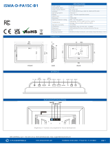
iSMA-B-2D1B
iSMA-B-2D1B-WD
SPECIFICATION
Power supply
230 V AC max. 8 VA
Special inputs
2x dry contact
Digital inputs
4x dry contact inputs for light and blind switches
Digital outputs
2x relay outputs for lights; max. load 4 A @ 230 V AC
1x TRIAC output for blind with interlocked relay direction
switch; max. load 1,5 A @ 230 V AC
Interface
RS485, 2x DALI interfaces (max 16 devices, integrated power
supply with 40 mA current limit for each interface), USB
Ingress protection
IP40 - for indoor installation
Temperature
Operating: 0°C to +50°C; Storage -40°C to +85°C
Relative humidity
5 to 95% RH (without condensation)
Connectors
2.5 mm2 screw terminals
WD – Plug / Socket Wieland GST15 series
Dimensions
123 x 137 x 55 mm
Mounting
DIN rail mounting (DIN EN 50022 specification)
Housing material
Plastic, self-extinguishing PC/ABS
BLOCK DIAGRAM
COMMUNICATION
RJ12 PIN DESCRIPTION
DALI INTERFACE
DIGITAL INPUTS
SPECIAL INPUTS
DIMENSIONS / TOP PANEL
OUTPUTS

iSMA CONTROLLI S.p.A. – Via Carlo Levi 52, 16010 Sant’Olcese (GE) - Italy |
support@ismacontrolli.com
www.ismacontrolli.com Installation Instruction| 1st Issue rev. 4 | 01/2022 page 2
WARNING
• Note, an incorrect wiring of this product can damage it and lead to other hazards.
• Make sure the product has been correctly wired before turning the power ON.
• Before wiring or removing/mounting the product, be sure to turn the power OFF. Failure to do so might cause electric shock.
• Do not touch electrically charged parts such as the power terminals. Doing so might cause electric shock.
• Do not disassemble the product. Doing so might cause electric shock or faulty operation.
• Use the product within the operating ranges recommended in the specification (temperature, humidity, voltage, shock, mounting direction,
atmosphere etc.). Failure to do so might cause fire or faulty operation.
• Firmly tighten the wires to the terminal. Insufficient tightening of the wires to the terminal might cause fire.
BLINDS CALIBRATION PROCEDURE
The calibration process is necessary always when the blind\shutter is used for the first time or when there is a need of recalibration or restoring to
the default settings. The time values are written into BLIND_UP_TIME/ BLIND_DOWN_TIME registers (values in the registers equal 0 by default).
The difference between BLIND_UP_TIME\BLIND_DOWN_TIME values from the first calibration and recalibration process cannot be greater than 20%.
The calibration can be run by monostable pushbuttons or three-state bistable pushbuttons.
1. To start the calibration process the roller-blind/shutter should be in the closed, lowest position.
2. Next, the roller- blind/shutter needs to be pulled up to the desired maximum position.
3. The roller-blind/shutter then needs to be pulled down back to the closed, lowest position.
4. Steps 2 and 3 should be repeated to complete the callibartion process
In order to complete the callibration process properly the following conditions must be fulfilled:
1. The difference between previous saved open/close time value and the average open/close time value obtained in the calibration
process cannot be greater than 20%, unless previous saved value is ‘0’.
2. The gap between two open time values cannot be greater than 20%.
3. The gap between two close time values cannot be greater than 20%.
Example: The first open time is 20 seconds, the second one can not exceed 24 seconds and can not be lower than 16 seconds.
4. Each open/close cycle needs to be initiated within 3 seconds of the end of previous one.
If the the above conditions are met, the open time values and the close time values are averaged and written to the BLIND_UP_TIME and
BLIND_DOWN_TIME registers. This is indicated by a quick up and down movement of the slats in case of the shutter control or quick up and down
movement of the blind.
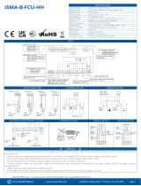
SLATS CALIBRATION PROCEDURE
The calibration process is necessary if the time of opening of the slats differs from the one stored in the SLATS_OPENING_TIME register (1 second by
default).
The calibration can be run by monostable pushbuttons.
1. To begin the calibration process the slats should be completely rotated down as seen on the figure (position 1).
2. From this position the slats need to be completely rotated up (position 2 on the figure) by short presing the up button. Each press of the
button rotates the slats by a step proportional to the value stored in SLATS_OPENING_TIME.
3. The slats need to be rotated down back to position 1.
4. The points no. 2 and 3 need to be repeated.
In order to complete the callibration process properly the following conditions must be fulfilled:
1. To complete the rotation cycle, the number of rotation steps to open slats should be equal to the number of
rotation steps to close slats.
2. The number of rotation steps in the rotation cycle must be greater than 5 and lower than 15.
3. Each open/close cycle needs to be initiated within 3 seconds of the end of previous one.
4. SLATS_NUMBER_OF_STEPS register needs to be set at the default value of 10 steps.
If the the above conditions are met, the new open time value is calculated by multiplying the old SLATS_OPENING_TIME by the number of open/close
steps made in the calibration cycle and then dividing the result by 10.
Example: SLATS_OPENING_TIME value is 1000 ms. Twelve steps are needed to complete the rotation cycle in the calibration process. The new value
stored in the register is: (1000 ms * 12) / 10, which gives 1200 ms.

iSMA CONTROLLI S.p.A. – Via Carlo Levi 52, 16010 Sant’Olcese (GE) - Italy |
support@ismacontrolli.com
www.ismacontrolli.com Installation Guideline| 1st Issue rev. 1 | 05/2022
INSTALLATION GUIDELINE
Please read the instruction before use or operating the device. In case of any questions after
reading this document, please contact the iSMA CONTROLLI Support Team
(support@ismacontrolli.com).
• Before wiring or removing/mounting the product, make sure to turn the power off. Failure to do so
might cause an electric shock.
• Improper wiring of the product can damage it and lead to other hazards. Make sure that the product
has been correctly wired before turning the power on.
• Do not touch electrically charged parts such as power terminals. Doing so might cause an electric shock.
• Do not disassemble the product. Doing so might cause an electric shock or faulty operation.
• Use the product only within the operating ranges recommended in the specification (temperature,
humidity, voltage, shock, mounting direction, atmosphere, etc.). Failure to do so might cause a fire or
faulty operation.
• Firmly tighten the wires to the terminal. Failure to do so might cause a fire.
• Avoid installing the product in close proximity to high-power electrical devices and cables, inductive loads, and switching devices.
Proximity of such objects may cause an uncontrolled interference, resulting in an instable operation of the product.
• Proper arrangement of the power and signal cabling affects the operation of the entire control system. Avoid laying the power and
signal wiring in parallel cable trays. It can cause interferences in monitored and control signals.
• It is recommended to power controllers/modules with AC/DC power suppliers. They provide better and more stable insulation for
devices compared to AC/AC transformer systems, which transmit disturbances and transient phenomena like surges and bursts to
devices. They also isolate products from inductive phenomena from other transformers and loads.
• Power supply systems for the product should be protected by external devices limiting overvoltage and effects of lightning
discharges.
• Avoid powering the product and its controlled/monitored devices, especially high power and inductive loads, from a single power
source. Powering devices from a single power source causes a risk of introducing disturbances from the loads to the control devices.
• If an AC/AC transformer is used to supply control devices, it is strongly recommended to use a maximum 100 VA Class 2
transformer to avoid unwanted inductive effects, which are dangerous for devices.
• Long monitoring and control lines may cause loops in connection with the shared power supply, causing disturbances in the
operation of devices, including external communication. It is recommended to use galvanic separators.
• To protect signal and communication lines against external electromagnetic interferences, use properly grounded shielded cables
and ferrite beads.
• Switching the digital output relays of large (exceeding specification) inductive loads can cause interference pulses to the electronics
installed inside the product. Therefore, it is recommended to use external relays/contactors, etc. to switch such loads. The use of
controllers with triac outputs also limits similar overvoltage phenomena.
• Many cases of disturbances and overvoltage in control systems are generated by switched, inductive loads supplied by alternating
mains voltage (AC 120/230 V). If they do not have appropriate built-in noise reduction circuits, it is recommended to use external
circuits such as snubbers, varistors, or protection diodes to limit these effects.
Electrical installation of this product must be done in accordance with national wiring codes and conform to
local regulations.
/