www.ismacontrolli.com
DMP221en | 1st Issue rev. 1 | 05/2022
iSMA-D-PA
User Manual
Android PC Panel

iSMA-D-PA User Manual
www.ismacontrolli.com
DMP221en | 1st Issue rev. 1 | 05/2022
page 2 of 19
Table of Contents
1 Introduction .................................................................................................................................... 3
1.1 Revison History .......................................................................................................................................3
2 Safety Rules..................................................................................................................................... 4
3 Technical Specification ................................................................................................................. 5
3.1 iSMA-D-PA7C-B1 .....................................................................................................................................5
3.2 iSMA-D-PA10C-B1/ iSMA-D-PA15C-B1 ..............................................................................................6
4 Standards and Norms .................................................................................................................. 8
4.1 EN 55022:2010+AC:2011 .....................................................................................................................8
4.2 EN 61000-3-2:2014................................................................................................................................8
4.3 EN 61000-3-3:2013................................................................................................................................8
4.4 EN 55024:2010 + A1:2015 ...................................................................................................................8
4.5 EN 60950-1:2006 + A11:2002 + A1:2010 + A12:2011 + A2:2013...............................................8
5 Dimensions ..................................................................................................................................... 9
5.1 iSMA-D-PA7C-B1 .....................................................................................................................................9
5.2 iSMA-D-PA10C-B1...................................................................................................................................9
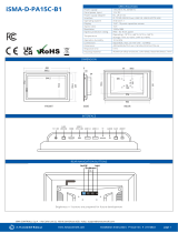
5.3 iSMA-D-PA15C-B1...................................................................................................................................9
6 Interfaces.......................................................................................................................................10
6.1 iSMA-D-PA7C-B1 .................................................................................................................................. 10
6.2 iSMA-D-PA10C-B1................................................................................................................................ 10
6.3 iSMA-D-PA15C-B1................................................................................................................................ 10
6.4 Setting USB Mode to OTG................................................................................................................. 11
7 Operation Guide..........................................................................................................................14
7.1 Rear Navigation Buttons.................................................................................................................... 14
7.2 Setting Static IP Address .................................................................................................................... 14
8 Installation.....................................................................................................................................18
8.1 Snap Joint Installation......................................................................................................................... 18
8.2 Wall Mount Installation ...................................................................................................................... 18
9 Android System............................................................................................................................19

iSMA-D-PA User Manual
www.ismacontrolli.com
DMP221en | 1st Issue rev. 1 | 05/2022
page 3 of 19
1 Introduction
The iSMA-D-PA panels are industrial PC panels with the Android operating system. Panels
have been designed to simplify the use of the Master Application Controller: iSMA-B-
MAC36NL.
They can be connected to the iSMA-B-MAC36NL, JACE, or other supervisor powered by
Niagara to display graphics by web page from the Niagara system.
As PC panels with Android, they can also be used as the user interface. There is an option
to install a dedicated application that allows communication with other devices in a BMS
system, for example, the iSMA CONTROLLIAndroid application designed for connectivity
with a Niagara station or any HTML 5 web-based controller.
Panels are available in three sizes: 7, 10, or 15 inches. They can be built into the wall
(VESA compatibility). They have an extensive menu in over 7 languages, in which the
displayed image can be easily customized.
Figure 1. iSMA-D-PA panels
1.1 Revison History
Rev. Date Description
1.0 18 Jul 2019 First edition
1.1 25 May 2022 7" Android panel added
Rebranded
Table 1. Revision history

iSMA-D-PA User Manual
www.ismacontrolli.com
DMP221en | 1st Issue rev. 1 | 05/2022
page 4 of 19
•
•
•
•
•
•
•
•
•
•
•
•
•
•
•
•
2 Safety Rules
Improper wiring of the product can damage it and lead to other hazards. Make sure
that the product has been correctly wired before turning the power on.
Before wiring or removing/mounting the product, make sure to turn the power off.
Failure to do so might cause an electric shock.
Do not touch electrically charged parts such as power terminals. Doing so might cause
an electric shock.
Do not disassemble the product. Doing so might cause an electric shock or faulty
operation.
Use the product only within the operating ranges recommended in the specification
(temperature, humidity, voltage, shock, mounting direction, atmosphere, etc.). Failure
to do so might cause a fire or faulty operation.
Firmly tighten the wires to the terminal. Failure to do so might cause a fire.
Avoid installing the product in close proximity to high-power electrical devices and
cables, inductive loads, and switching devices. Proximity of such objects may cause an
uncontrolled interference, resulting in an instable operation of the product.
Proper arrangement of the power and signal cabling affects the operation of the entire
control system. Avoid laying the power and signal wiring in parallel cable trays. It can
cause interferences in monitored and control signals.
It is recommended to power controllers/modules with AC/DC power suppliers. They
provide better and more stable insulation for devices compared to AC/AC transformer
systems, which transmit disturbances and transient phenomena like surges and bursts
to devices. They also isolate products from inductive phenomena from other
transformers and loads.
Power supply systems for the product should be protected by external devices limiting
overvoltage and effects of lightning discharges.
Avoid powering the product and its controlled/monitored devices, especially high
power and inductive loads, from a single power source. Powering devices from a single
power source causes a risk of introducing disturbances from the loads to the control
devices.
If an AC/AC transformer is used to supply control devices, it is strongly recommended
to use a maximum 100 VA Class 2 transformer to avoid unwanted inductive effects,
which are dangerous for devices.
Long monitoring and control lines may cause loops in connection with the shared
power supply, causing disturbances in the operation of devices, including external
communication. It is recommended to use galvanic separators.
To protect signal and communication lines against external electromagnetic
interferences, use properly grounded shielded cables and ferrite beads.
Switching the digital output relays of large (exceeding specification) inductive loads can
cause interference pulses to the electronics installed inside the product. Therefore, it
is recommended to use external relays/contactors, etc. to switch such loads. The use
of controllers with triac outputs also limits similar overvoltage phenomena.
Many cases of disturbances and overvoltage in control systems are generated by
switched, inductive loads supplied by alternating mains voltage (AC 120/230 V). If they
do not have appropriate built-in noise reduction circuits, it is recommended to use
external circuits such as snubbers, varistors, or protection diodes to limit these effects.

iSMA-D-PA User Manual
www.ismacontrolli.com
DMP221en | 1st Issue rev. 1 | 05/2022
page 5 of 19
3 Technical Specification
3.1 iSMA-D-PA7C-B1
Panel Type Industrial LCD panel A grade
Operating System Android 6.0
Screen Type LED; backlight lifetime ≥50000 h,
Size 7”
Aspect Ratio 16:9
Resolution 1024x600
Luminance Standard 300 nit
Contrast 800:1/1000:1
Active Area 222.7x125.2 mm/344.2x193.6 mm
Display Color 16.7 M
View Angle 80/80/80/80 / 89/89/89/89
Response Time 5 ms
Installation Compatible with VESA, for embedding
Menu Languages English, French, German, Spanish, Chinese, Italian, Russian, Portuguese, Arabic
Touch Type 10-point capacitive touch screen
Material Metal/aluminum alloy
Interface IP, RS232, TF/SD Card, USB 2.0, USB 3.0, USB C (OTG USB)/ USB 3.0 (OTG USB), HDMI (10”
panel), RJ45, Audio output
Power Port 12 VDC
Anti-interference Anti-interference electromagnetic compatibility; electromagnetic interference
Anti-vibration 5-19 HZ/1.0 mm amplitude; 19-200 HZ/1.0 g accelerated speed
Temperature Operating temperature: -10°C to 60°C
(14°F to 140°F)
Storage temperature: -10°C to 60°C (14°F
to 140°F)

iSMA-D-PA User Manual
www.ismacontrolli.com
DMP221en | 1st Issue rev. 1 | 05/2022
page 6 of 19
Humidity Operation humidity: 25% to 85% RH Storage humidity: 10% to 90%RH
Anti-static 4 KV-8 KV; (customized max. 16 KV)
Rated Voltage 100 V AC~240 V to DC 12 V-24 V
Rated Frequency 50 Hz/60 Hz
Power Supply AC 110-240 V, 50/60 Hz
Power Supply
Adapter
EU, UK, or US
Power Power consumption ≤30 W Power standby ≤1.5 W
Dimensions 293.6x193.6x48.5 mm (11.560x7.622x1.909 in)/420.0x269.0x70.0 mm
(16.535x10.591x2.756 in)
IP IP65 – for front panel
Table 2. Technical specification of the iSMA-D-PA7C-B1 panel
3.2 iSMA-D-PA10C-B1/ iSMA-D-PA15C-B1
Panel Type Industrial LCD panel A grade
Operating System Android 7.1
Screen Type LED; backlight lifetime ≥50000 h,
Size 10.1’’/15.6”
Aspect Ratio 16:9
Resolution 1366x768/1920x1080
Luminance Standard 300 nit
Contrast 800:1/1000:1
Active Area 222.7x125.2 mm/344.2x193.6 mm
Display Color 16.7 M
View Angle 80/80/80/80 / 89/89/89/89
Response Time 5 ms

iSMA-D-PA User Manual
www.ismacontrolli.com
DMP221en | 1st Issue rev. 1 | 05/2022
page 7 of 19
Installation Compatible with VESA, for embedding, wall mount
Menu Languages English, French, German, Spanish, Chinese, Italian, Russian, Portuguese, Arabic
Touch Type 10-point capacitive touch screen
Material Metal/aluminum alloy
Interface IP, RS232, TF/SD Card, USB 2.0, USB 3.0, USB C (OTG USB)/ USB 3.0 (OTG USB), HDMI (10”
Panel), RJ45, Audio Output
Power Port 12 VDC
Anti-interference Anti-interference electromagnetic compatibility; electromagnetic interference
Anti-vibration 5-19 HZ/1.0 mm amplitude; 19-200 HZ/1.0 g accelerated speed
Temperature Operating temperature: -10°C to 60°C
(14°F to 140°F)
Storage temperature: -10°C to 60°C (14°F
to 140°F)
Humidity Operation humidity: 10% to 80%RH Storage humidity: 10% to 90%RH
Anti-static 4 KV-8 KV; (customized max. 16 KV)
Rated Voltage 100 V AC~240 V to DC 12 V-24 V
Rated Frequency 50 Hz/60 Hz
Power Supply AC 110-240 V, 50/60 Hz
Power Supply
Adapter
EU, UK, or US
Power Power consumption ≤30 W Power standby ≤1.5 W
Dimensions 293.6x193.6x48.5 mm (11.560x7.622x1.909 in)/420.0x269.0x70.0 mm
(16.535x10.591x2.756 in)
IP IP65 – for front panel
Table 3. Technical specification of the iSMA-D-PA10C-B1/ iSMA-D-PA15C-B1 panels

iSMA-D-PA User Manual
www.ismacontrolli.com
DMP221en | 1st Issue rev. 1 | 05/2022
page 8 of 19
4 Standards and Norms
4.1 EN 55022:2010+AC:2011
Electromagnetic compatibility of multimedia equipment. Emission Requirements.
4.2 EN 61000-3-2:2014
Electromagnetic compatibility (EMC). Limits for harmonic current emissions for
equipment input current ≤ 16 A per phase).
4.3 EN 61000-3-3:2013
Electromagnetic compatibility (EMC). Limits for voltage changes, voltage fluctuations and
flicker in public low-voltage supply systems, for equipment with rated current ≤ 16 A per
phase.
4.4 EN 55024:2010 + A1:2015
Information technology equipment. Immunity characteristics. Limits and methods of
measurement.
4.5 EN 60950-1:2006 + A11:2002 + A1:2010 + A12:2011 + A2:2013
Information technology equipment. Safety General requirements specifies requirements
intended to reduce risks of fire, electric shock or injury for the OPERATOR and layman
who may come into contact with the equipment and, where specifically stated, for a
SERVICE PERSON.

iSMA-D-PA User Manual
www.ismacontrolli.com
DMP221en | 1st Issue rev. 1 | 05/2022
page 9 of 19
5 Dimensions
5.1 iSMA-D-PA7C-B1
Figure 2. Dimesions of iSMA-D-PA7C-B1
5.2 iSMA-D-PA10C-B1
Figure 3. Dimensions of iSMA-D-PA10C-B1
5.3 iSMA-D-PA15C-B1
Figure 4. Dimensions of iSMA-D-PA15C-B1

iSMA-D-PA User Manual
www.ismacontrolli.com
DMP221en | 1st Issue rev. 1 | 05/2022
page 10 of 19
6 Interfaces
The monitor recognizes and selects the signal automatically. The only exception is the
USB in the OTG mode: the USB port needs to be manually set to the OTG mode. For full
instruction see section Setting USB Port to OTG mode. In the 10” Android Panel USB C is
automatically set to the OTG mode; there is no need to change the settings.
6.1 iSMA-D-PA7C-B1
Figure 5. Interfaces of iSMA-D-PA7C-B1
6.2 iSMA-D-PA10C-B1
Figure 6. Interfaces of iSMA-D-PA10C-B1
6.3 iSMA-D-PA15C-B1
Figure 7. Interfaces of iSMA-D-PA15C-B1

iSMA-D-PA User Manual
www.ismacontrolli.com
DMP221en | 1st Issue rev. 1 | 05/2022
page 11 of 19
•
•
•
6.4 Setting USB Mode to OTG
Go to the main menu of the Android Panel PC – a round, white icon with dots at the
bottom center of the screen:
Figure 8. Main menu
Go to the Settings:
Figure 9. Settings
Go to the Developer options:

iSMA-D-PA User Manual
www.ismacontrolli.com
DMP221en | 1st Issue rev. 1 | 05/2022
page 12 of 19
•
•
Figure 10. Developer options
Set the USB Mode to the OTG Mode and turn on USB debugging:
Figure 11. USB mode and USB debugging
Set the USB Configuration to MTP:

iSMA-D-PA User Manual
www.ismacontrolli.com
DMP221en | 1st Issue rev. 1 | 05/2022
page 13 of 19
Figure 12. Select USB configuration

iSMA-D-PA User Manual
www.ismacontrolli.com
DMP221en | 1st Issue rev. 1 | 05/2022
page 14 of 19
•
•
7 Operation Guide
7.1 Rear Navigation Buttons
The rear navigation buttons are used to turn the device on and off. Brightness +/- buttons
are prepared for future development:
Figure 13. Rear navigation buttons
Symbol Name Instruction
Brightness +/- Choose + Buttons prepared for future development
Brightness +/- Choose -
On/Off On/Off button Start-up/Shut down the monitor. The button has to be
pressed for a few seconds for both turning on and off.
When turning on, wait a few seconds after pressing the
button.
Table 4. Operating of rear navigation buttons
7.2 Setting Static IP Address
Follow the instruction steps to set a static IP address:
Follow steps 1 and 2 from the point 1.7 (go to the Settings of the Adroid Panel PC).
Go to the More option:

iSMA-D-PA User Manual
www.ismacontrolli.com
DMP221en | 1st Issue rev. 1 | 05/2022
page 15 of 19
•
•
Figure 14. Settings - More
Go to the Ethernet:
Figure 15. Ethernet
Go to the Ethernet IP mode:

iSMA-D-PA User Manual
www.ismacontrolli.com
DMP221en | 1st Issue rev. 1 | 05/2022
page 16 of 19
•
•
Figure 16. Ethernet IP mode
Choose the “static” option:
Figure 17. Setting Ethernet IP mode
Insert the IP address and other information and click CONNECT:

iSMA-D-PA User Manual
www.ismacontrolli.com
DMP221en | 1st Issue rev. 1 | 05/2022
page 17 of 19
Figure 18. Inserting Ethernet information

iSMA-D-PA User Manual
www.ismacontrolli.com
DMP221en | 1st Issue rev. 1 | 05/2022
page 18 of 19
•
•
•
•
8 Installation
Do not place the monitor next to the radiator or heat source.
Do not let any objects press or twine around the power cable or VGA cable.
Do not place the monitor near a water source or humid places.
Do not block off the back vents, which can dissipate heat generated inside it, to
prevent damage of components.
8.1 Snap Joint Installation
Follow the below steps to install the monitor with four snap joints buckle hole:
Figure 19. Embed with snap joint installation
8.2 Wall Mount Installation
Figure 20. Wall mount installation

iSMA-D-PA User Manual
www.ismacontrolli.com
DMP221en | 1st Issue rev. 1 | 05/2022
page 19 of 19
9 Android System
WARNING!
In case any custom modifications or any other changes are introduced to the Android
system originally installed on the equipment, the warranty automatically expires. The
only exception is when the iSMA CONTROLLI itself announces the possibility of
introducing custom modifications to the Android system originally installed on the
equipment precisely specifying the range of such modifications.
/