Page is loading ...


2
1. Safety Instructions .................................. 3
1.1. For Your Orientation........................................................... 3
1.2. Pictogram Definitions........................................................ 3
2. Understanding The
Pumping Stations .................................. 4
2.1. Main Features..................................................................... 4
2.2. Pumping Station Control ................................................... 4
2.3. Pumping Station Components.......................................... 5
3. Installation ............................................... 5
3.1. Preparations For Installation............................................ 5
3.2. Laying The Exhaust Line ................................................... 5
3.3. Venting Units....................................................................... 5
3.4. Electrical Connections ...................................................... 6
3.5. Connecting The Vacuum Unit .......................................... 6
Connecting The Pumping Station
Via A Bellows...................................................................... 6
3.6. Cooling ................................................................................. 6
3.7. Pumping Station Connections Plan
General Schema................................................................. 7
Connection Involving
Rotary Vane Vacuum Pumps............................................ 8
Connection Involving Diaphragm Pumps....................... 9
4. Operations .............................................. 10
4.1. Transportation Protection .............................................. 10
42. Filling In The Lubricant.................................................... 10
4.3. Operational Behaviour With Gas Load......................... 10
4.4. Starting .............................................................................. 11
4.5. Switching OFF And Venting............................................ 11
5. What To Do In Case
Of Breakedowns? .................................. 11
6. Maintenance .......................................... 12
6.1. Replacing The Lubricant Reservoir And
The Operating Fluid Change........................................... 12
7. Service .................................................... 13
8. Technical Data ....................................... 14
8.1. Dimensions........................................................................ 15
9. Accessories ........................................... 16
10. Spare Parts ............................................. 16
Declaration Of Contamination .................... 17
Declaration OF Conformity............ (last page)
PPlleeaassee nnoottee::Current operating instructions are available via
www.pfeiffer-vacuum.net.
Index
Page Page

3
Caution, danger of damage to the pump or the
system.
CAUTION
1. Safety Instructions
☞Read and follow all instructions in this manual.
– Inform yourself regarding:
– Hazards which can be caused by the pumping station;
– Hazards which can be caused by your system;
– Hazards which can be caused by the medium being
pumped.
☞Avoid exposing any part of the body to vacuum.
☞Observe the safety and accident prevention regulations.
☞Regularly check that all accident prevention measures are
being complied with.
☞Do not operate the turbo pumping station with open high
vacuum flange.
☞Use at least 4 bracket screws to connect the high vacuum
flange.
☞The unit has been accredited protection class IP 30. When
the unit is operated in environments which require other
protection classes, the necessary measures must be
taken.
☞Do not carry out any unauthorised conversions or
alterations to the turbo pumping station.
☞The control of turbopumping stations has been so
designed that the pumps re-start automatically following
an interruption to the mains power supply. For this reason,
access to the vacuum chambers (for example, via doors,
flanges, valves) may only be opened once the pumping
station has been switched off.
☞When returning individual components please observe the
shipping instructions (refer to the operating instructions
for the pumping station components).
Modifications reserved.
Warning, danger of personal injury.
WARNING
1.1.
For Your Orientation
Instructions in the text
➡Working instruction: here, you have to do something.
Symbols used
The following symbols are used throughout in illustrations.
High vacuum flange
Cooling water connection
Electric connection
Exhaust
Abbreviations used
DCU = Display and operating unit
TC = Electronic drive unit, turbopump
TPS = Power supply
Position numbers
The same pump and accessory parts have the same position
numbuers in all illustrations.
1.2. Pictogram Definitions
Warning, danger of burns from touching hot
parts.
WARNING
Warning, danger of injury from rotating parts.
WARNING
Please note, attention to particulary important
information on the product, handling the
product or to a particular part of the documen-
tation.
☞
PLEASE NOTE

4
The plug and play type pumping stations are fully
automatically operating pumping units.
The integrated power part with the Display And Operating
Unit DCU 001 serves to control and monitor the pumping
station and works in conjunction with the Electronic Drive
Unit TC 600.
Cooling
Standard type: Air cooling integrated in the casing
(up to 35 °C ambient temperature).
Alternative: Water cooling (please see Section 9.
Accessories).
Details regarding the pumping station
components can be found in the respective
operating instructions.
The possible pumping station variants and
their components are set out in Section 2.3. of
these operating instructions.
Transport
Lifting gear, which may only be attached to the ring screws,
can be used to transport the pumping stations.
The threaded holes for the ring screws are located in the high
vacuum flange.
The two carrying handles 3 (please see the illustration above)
are provided only for manual carrying.
☞
PLEASE NOTE
2. Understanding The Pumping Stations
Where the delivery of pumping stations include
a rotary vane vacuum pump it must be noted
that this rotary vane pump is supplied without a
filling of operating fluid.
Before first time starting, the rotary vane
vacuum pump must be filled with operating fluid.
The operating fluid is contained in a pack inclu-
ded with the delivery consignment.
Before first-time starting on pumping stations
equipped with a Diaphragm Pump MVP 055-3 or
a rotary vane vacuum pump, the transportation
protection must be removed (please see the
sticker an the pumping station).
For the procedure please refer to Section 4.1..
Proper Use
– The turbomolecular pumping stations may only be used for
the purpose of generating vacuum.
– The turbomolecular pumping stations may only be
operated in the existing configuration.
Improper Use
The following is regarded, inter alia, as improper:
– The pumping of explosive or corrosive gases.
– Operating the pumping stations in areas where there is a
danger of explosion.
– The use of accessories which are not named in this
manual or which have not been agreed by the
manufacturer.
Improper use will cause all claims for liability and guarantees
to be forfeited.
2.2. Pumping Station Control
☞
PLEASE NOTE
CAUTION
Pumping Station Pumping Station Control Operating Instructions
for DCU/TPS
TSH 071 TC 600 with
TSU 071 DCU 001 and TPS 100
TSH 261 TC 600 with PM 0477 BN/
TSU 261 DCU 001 and TPS 200 PM 0521 BN
TSH 521 TC 600 with
TSU 521 DCU 001 and TPS 300
2.1. Main Features
1
2
3
3
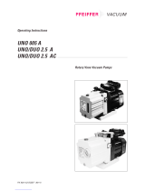
Turbomolecular Drag Pumping Station TSH 521
1 High vacuum flange
2 Display And Operating Unit DCU
3 Carrying handle

5
3.2. Laying The Exhaust Line
Please observe the backing pump operating
instructions when laying the exhaust line.
Exhausted gases and vapours can be hazardous
to health and cause environmental pollution.
3.3. Venting Units
The pumping stations are equipped with Venting valve
TVF 005 as standard.
Control is effected via the pre-selected setting on Electronic
Drive Unit TC 600.
The venting mode of the TVF 005 is selected via the DCU.
Drying Unit TTV 001 (Accessory)
The drying unit keeps moisture away from the apparatus
when venting with atmospheric air.
➡Secure Drying Unit TTV 001 to the rear side of the pumping
station casing using the two knurled screws.
Where the casing variant with additional cover for the
rotary vane vacuum pump is involved the drying unit must
be fitted within this cover.
➡Make the connection to the venting valve with a PVC hose
(please refer to Section 9. Accessories).
CAUTION
3.1. Preparations For Installation
Do not carry out any unauthorised conversions
or alterations to the turbo pumping station.
– Only remove the blank flange from the high vacuum side
immediately before connection.
– The lubricant reservoir is already fitted to turbopumps and
filled.
– Where the use of rotary vane vacuum pumps is involved,
the operating fluid is included in the delivery consignment
and must be filled into the pump before first time operating.
– Diaphragm pumps do not require lubricant.
– Permissible magnetic fields:
TSH 071/TSU 071 ≤4 mT
TSH 261/TSU 261 ≤5.5 mT
TSH 521/TSU 521 ≤5 mT
– The pumping station should be erected on a horizontal
surface.
On delivery, the pumping station is provided with four elastic
buffers on the underside.
In addition, and to render the pumping station mobile, rollers
can be fitted (please see Section 9. Accessories).
WARNING
3. Installation
2.3. Pumping Station Components
PPuummppiinngg SSttaattiioonnTTSSHH 007711TTSSHH 226611TTSSHH 552211OOppeerraattiinngg IInnssttrruuccttiioonnss
TTSSUU 007711TTSSUU 226611TTSSUU 552211
CCoommppoonneennttss
TTuurrbboommoolleeccuullaarr DDrraagg PPuummppTMH 071 PM 0504 BN
TMU 071
TMH 261 PM 0470 BN
TMU 261
TMH 521 PM 0496 BN
TMU 521
DDiiaapphhrraaggmm PPuummppMVP 015-2 PU 0012 BN
MVP 035-2 MVP 035-2 PU 0011 BN
MVP 055-3 MVP 055-3 MVP 055-3 PU 0011 BN
RRoottaarryy VVaannee VVaaccuuuumm PPuummppDUO 2.5 DUO 2.5 DUO 2.5 PK 0152 BN
UNO 005 A UNO 005 A UNO 005 A PK 0152 BN
DUO 5 DUO 5 DUO 5 PK 0197 BN
DUO 10 DUO 10 DUO 10 PK 0170 BN
VVeennttiinngg VVaallvveeTVF 005 TVF 005 TVF 005 PM 0 507 BN
For further accessories please refer to Section 9.

6
Piping must be connected free of stress.
A bellows fitted in the piping will compensate
for any stress arising.
3.6. Cooling
The pumping stations have been designed to be air cooled as
standard where ambient temperatures of up to 35 °C are
involved.
If required, conversion to water cooling is possible (for water
cooling please refer to the "Accessories").
Water cooling is necessary where casing
heating is being used.
CAUTION
CAUTION
3.4. Electrical Connections
The electrical connections must be effected in
accordance with local regulations. The voltage
requirements shown on the rating plate must
comply with the mains voltage.
Alternating current is required for operating the pumping
station.
The mains connection cable (length 2.5 m) is provided on the
pumping station.
➡Plug in mains connection plug (the pumping station can
now be operated).
Accessory Connections:
For the electrical connections of accessories please refer to
Section 3.7. "Connections Plan".
3.5. Connecting The Vacuum Unit
There should be no unilateral loading on the high
vacuum flange.
The weight of a vacuum chamber freely flanged
on the vacuum flange must not exceed, with the
TSH/TSU 071 maximum 200 N (20 kg), with
TSH/TSU 261 maximum 500 N (50 kg), and with
TSH/TSU 521 maximum 1000 N (100 kg).
The utmost cleanliness must be observed
when fitting all high vacuum parts. Unclean
components prolong the pumping time.
➡Only remove the blank cover on the high vacuum flange
once the vacuum unit is ready for connection so that no
moisture, which would prolong the pumping time to
attainment of final vacuum, precipitates in the pump.
➡The use of a splinter shield in the high vacuum flange
protects against foreign bodies (please see accessories
for the turbopump).
Connecting The Pumping Station Via A
Bellows
Advantage: Reduced vibration transmission.
The pumping station must be mechanically anchored.
➡Screw the pumping station to a holder with threaded
screws M10. The elastic buffers need not be removed.
☞
PLEASE NOTE
CAUTION
CAUTION

7
3.7. Pumping Station Connections Plan
General Schema
PE
1P6
1G5
DCU
1P6
POWER SUPPLY
TC 600
MAINS
RS 485
X3
OPTION
TPG 251/252
RELAY-BOX
OPTION
VAC.-MEASURANCE
TERMINAL STRIP X1
3
TERMINAL STRIP
TSHU 071 / 261 / 521
RS 485
REMOTE
VENT.
FANHEAT/TMS
FV-PUMP X2
PM 051 409 -X
13
14
1S2
1X2
PE
PE
TC
1E5
PM 051 101 -T
POT.-EQUALIZATION
FRAME GROUNDING
M
1~
UV
PE
1M7
M
1~
UV
PE
1E8
FEEDER
OPTION
HEATER
BACKING PUMP FAN OPTION
FORE-VACUUM
SAFETY VALVE
TVV 001
OPTION
VENT.-VALVE
TVF-005
1Y8 2Y6
PM 051 406 -S

8
grün
2A
1A
5B
4B
1S2
1 2 43
HEAT/TMS
PE
L
N
1E5
1
X1
5
X1
2
X1
6
X1
3
X1
7
X1
4
X1
8
X1
9
X1
10
X1
15
X1
16
X1
L
1P6
PE
N
TPG 251
TPG 252
OPTION
M
1~
UV
PE
1M7
11 13
12 14
17
M
1~
UV
PE
1E8
L
1G5
PE N
1G5
POWER SUPPLY
PENL
1X2
PE
POT.-EQUALIZATION
FRAME GROUNDING
OPTION
TURBO HEATER
BACKING PUMP FAN
BACKING-PUMP AS ROTARY-VANE-PUMP
21
X1
22
X1
A1
A2
1K1
12 21
14
/1.2
/1.2
12
21
14
1K1
/1.4
K
A
1
2
+3
4
FV-PUMP
ws
PM 051 409 -X
gn bn ge
Z
MAINS
TURBO
PE PE
18
OPTION
19
20
A1
A2PE
1Y8
TVV 001
FORE-VACUUM SAFETY VALVE
Fuse-rating according to type-plate
Bridge relay contacts 11 and 21
and also 14 and 24
(DU=-cable end sleeves)
Connection to Kl.21 and 22
with DUO sleeve 1.5 mm
Fit switch 1S2 in such a
way that terminal positions
1A and 4B point upwards.
Connection Involving Rotary Vane Vacuum Pumps
PM 051 408 -S

9
grün
2A
1A
5B
4B
1S2
1 2 43
HEAT/TMS
PE
L
N
1E5
1
X1
5
X1
2
X1
6
X1
3
X1
7
X1
4
X1
8
X1
9
X1
10
X1
L
1P6
PE
N
TPG 251
TPG 252
OPTION
11 13
12 14
L
1G5
PE N
PENL
1X2
PE
POT.-EQUALIZATION
FRAME GROUNDING
OPTION
TURBO HEATER
1
2
+3
4
FV-PUMP
ws
PM 051 409 -X
gn bn ge
Z
MAINS
BACKING-PUMP AS DIAPHRAGM-PUMP
21
X1
22
X1
240VAC/5A
SOLID-STATE-RELAY
PE
TURBO
PE
M
1~
UV
PE
1E8
FAN
1715
X1
16
X1
M
1~
UV
PE
1M7
BACKING PUMP
18
1G5
POWER SUPPLY
20
19
A1
A2PE
1Y8
TVV 001
OPTION
FORE-VACUUM SAFETY VALVE
Fuse-rating according to type-plate
Connection to Kl.21 and 22
with DUO sleeve 1.5 mm
Fit switch 1S2 in such a
way that terminal positions
1A and 4B point upwards.
Connection Involving Diaphragm Pumps
PM 051 407 -S

10
4. Operations
4.2. Filling In The Lubricant
– The ttuurrbboommoolleeccuullaarr ddrraagg ppuummppbearing has been filled
with the required amount of lubricant in the works.
– The ddiiaapphhrraaggmm ppuummppis lubricated for the whole of its
working life.
– The rroottaarryy vvaannee vvaaccuuuumm ppuummppmust be filled with
operating fluid P3 before first time starting. A filling of
operating fluid is included with the delivery consignment.
Procedure:
(please also refer to Section 6.1.).
➡Unscrew two screws on the right-hand side panel. Slightly
lift the panel and remove.
➡Unscrew operating fluid filler screw 8.
➡Unscrew the locking screw on the operating fluid flask
(included) and screw on the filling hose (in the side panel).
➡Insert the filling hose in the operating fluid filler opening
and allow operating fluid to flow in; the amount and type of
operating fluid is shown on the rating plate.
➡Screw in operating fluid filler screw 8 and take care with
the O-ring.
➡Re-secure the filling hose in the side panel.
➡Fit the side panel back onto the pumping station.
4.3. Operational Behaviour With Gas Load
Water cooling is necessary if the pumping
station is to be operated with gas load.
Details regarding the operational behaviour with gas load can
be found in the respective turbopump operating instructions.
CAUTION
4.1. Transportation Protection
Pumping stations which contain a Diaphragm Pump
MVP 055-3 or a rotary vane vacuum pump are shipped with
transportation protection (please see also the sticker on the
pumping station).The following must be removed before
first-time starting:
➡Remove both side panels from the pumping station by
unscrewing each two screws.
➡Disconnect the earthing cable from the side panels.
➡Unscrew the Allan head screws 10 (M6) from both sides of
the pumping station base.
10
10
➡The transportation protection is now removed. The side
panels can be re-fitted. Caution: Re-connect the earthing
cable.

11
– Once the self test has been successfully completed
(duration: TSH/TSU 071 approximately 10 s; TSH/TSU 261
approximately 10 s; TSH/TSU 521 approximately 15 s),
the pumping station begins to operate.
– If the vacuum pump does not start after being switched on
please refer to "What To Do In Case Of Breakdowns" In the
repective operating instructions for the turbopump.
– The turbomolecular drag pump starts up automatically.
The start up phase up to attainment of the rotation speed
switchpoint is dependent on the size of the vacuum
chamber. For start up times in respect of the turbopump
please refer to "Technical Data" in the relevant operating
instructions.
Where the incidence of water vapour is
anticipated, before starting the pumping
station it is recommended to open the gas
ballast valve on the backing pump by hand. If it
is ascertained that the intake pressure of the
pump increases or is unusually high, the valve
can be opened while the pumping station is
running. Once the final pressure has stabilized
the valve can be closed again.
4.5. Switching OFF And Venting
➡The complete pumping station is switched off with the
key 6 "Pumpstand EIN/AUS" / "pumping station ON/OFF".
– Turbopump and vacuum chamber are vented via Venting
Valve TVF 005 which opens for 0.3 seconds when the
venting frequency does not attain 50% of the final rotation
speed. It then closes again for 10 seconds and is then
opened for the venting time of 3,600 seconds (1 hour).
– The venting mode can be changed via the DCU.
➡Where water cooling is involved: Shut off water supply.
☞
PLEASE NOTE
1
2
8
7
6
345
Pumping station front panel
1 LCD display
2 Status display
3 Malfunction
acknowledgment key
4 Key "left"
5 Key "right"
6 Pumping station ON/OFF key
7 Red illuminating diode for
malfunction status
8 Green illuminating diode for
operations status
4.4. Starting
Turbopump rotors turn at great speed. When the
high vacuum flange is open there is a danger of
personal injury and of damage to the pump resul-
ting from the falling in of objects.
Therefore, never operate the pump with an open
high vacuum flange.
➡With water cooling: Open the cooling water supply and
check flow.
➡Switch on the pumping station with the "Pumpstand
EIN/AUS" ("pumping station ON/OFF") key (6) on the front
panel.
WARNING
5. What To Do In Case Of Breakdowns?
Please refer to the operating instructions for the individual
components for information on the elimination of
malfunctions.

12
6. Maintenance
Maintenance on the individual components of
the pumping station should be carried out in
accordance with the instructions in the
respective sections of the relevant operating
instructions.
6.1. Replacing The Lubricant Reservoir And
The Operating Fluid
– The ddiiaapphhrraaggmm ppuummppbearings are lubricated for the whole
of their working life.
– The lubricant reservoir in respect of the ttuurrbbooppuummppshould
be replaced at least once a year. Where extreme
operating conditions or unclean processes are involved,
the replacement interval should be shorter.
Procedure:
➡Unscrew the four screws from the cover plate and remove.
➡Unscrew four screws from the turbopump holding plate.
➡Lift out the turbopump with the holding plate from the
pumping station.
➡Carry out the change of the lubricant reservoir in
accordance with the turbopump operating instructions.
The Lubricant can contain toxic substances
from the medium pumped. Lubricant must be
disposed of in accordance with the respective
regulations.
Safety instructions data sheet for the lubricant
on request.
– The operating fluid for the rroottaarryy vvaannee vvaaccuuuumm ppuummpp
should be changed at least once a year.
Procedure:
➡Unscrew the two screws on the right hand side panel.
Slightly lift up the side panel and remove.
➡Unscrew two screws 4 and pull out perforated plate 5 to
the right hand side.
➡Exert slight downward pressure on operating fluid duct 6,
turn 90° and bring into the forward position.
➡Unscrew operating fluid drain screw 7 and drain operating
fluid via operating fluid duct 6 into a suitable container.
The temperature of the operating fluid can be as
high as 80 °C.
Toxic gases and vapours can escape from the
operating fluid which can be enriched with
substances which represent a hazard to health.
Disposal must be carried out in accordance with
the relevant regulations.
WARNING
WARNING
WARNING
☞
PLEASE NOTE
Lubricant reservoir
on turbomolecular pumps Order number
TMH/U 071 PM 073 073 -T
TMH/U 261 PM 063 265-T
TMH/U 521 PM 063 265 -T
Operating fluid for rotary
vane vacuum pumps Pack size Order number
P3 1 l PK 001 106 -T
P3 5 l PK 001 107 -T
P3 20 l PK 001 108 -T
45769
4
8
Changing the operating fluid on rotary vane vacuum pumps
4 Screws (2 pieces)
5 Perforated plate
6 Operating fluid duct
7 Operating fluid drain screw
8 Operating fluid filler screw
9 Sight glass
Order numbers for the lubricant reservoir on turbopumps and
operating fluid on rotary vane vacuum pumps
➡Screw back in operating fluid drain screw 7 taking care
with the O-ring.
➡Fill in operating fluid as described in Section 4.1. of these
operating instructions.
➡Re-fit the perforated plate and the side panel.
➡Check the operating fluid daily where non-stop operations
are involved, otherwise each time the pumping station is
switched on.
Further information regarding changes of
operating fluid can be found in the operating
instructions for the respective rotary vane
vacuum pump.
☞
PLEASE NOTE

13
7. Service
Do make use of our service facilities
In the event that repairs are necessary on your pumping
station a number of options are available to you to ensure any
system down time is kept to a minimum:
– Have the pump repaired on the spot by our Pfeiffer
Vacuum Service Engineers,
– Return individual components to the manufacturer for
repairs,
– Replace individual components.
Local Pfeiffer Vacuum representatives can provide full
details.
Before returning:
➡Dismantle all accessories.
➡Drain lubricant/operating fluid (please see Section 6.1.).
➡If the units are free of harmful substances please attach a
clearly visible notice "Free of harmful substances" (both on
the unit and also on the delivery note and any accompany-
ing letters).
"Harmful substances" are substances and preparations as
defined in the current, local, dangerous substances
regulations; in the U.S.A. as
"materials in accordance with the Code of Federal
Regulations (CFR) 49 Part 173.240 Definition and Preparation".
We will carry out the decontamination and invoice this work
to you if you have not attached this note. This also applies
where the operator does not have the facilities to carry out
the decontamination work. Units which are contaminated
microbiologically, explosively or radioactively cannot be
accepted as a matter of principle.
Fill out the declaration of contamination
➡In every case the "Declaration of Contamination" must be
completed diligently and truthfully.
➡A copy of the completed declaration must accompany the
unit; any additional copies must be sent to your local Pfeif-
fer Vacuum Service Center.
Please get in touch with your local Pfeiffer Vacuum represen-
tatives if there are any questions regarding contamination.
Decontaminate units before returning or
possible disposal. Do not return any units which
are microbiologically, explosively or
radioactively contaminated.
Returning contaminated units
If contaminated have to be returned for maintenance/repair,
the following instructions concerning shipping must be
followed:
➡Neutralise the pump by flushing with nitrogen or dry air.
➡Seal all openings to the air.
➡Seal pump or unit in suitable protective foil.
➡Ship units only in appropriate transport containers.
Repair orders are carried out according to our
general conditions of sale and supply.
If repairs are necessary, please send the unit together with a
short damage description to your nearest Pfeiffer Vacuum
Service Center.
Contact addresses and telephone hotline
Contact addresses and telephone numbers can be found on
the back cover of these operating instructions.
☞
PLEASE NOTE
WARNING

14
8. Technical Data
Pumping Station Unit TSH 071 TSH 071 TSU 071 TSH 261 TSU 261 TSH 521 TSH 521 TSU 521 TSU 521
Connection, nominal diameter DN 40 ISO-KF DN 63 ISO-K DN 63 CF-F DN 100 ISO-K DN 100 CF-F DN 100 ISO-K DN 160 ISO-K DN 100 CF-F DN 160 CF-F
Pumping speed for
Nitrogen N2l/s 33 60 60 210 210 300 510 300 510
Final pressure with
rotary vane vacuum pumps mbar < 1 · 10-7 < 1 · 10-7 < 5 · 10-10 < 1 · 10-7 < 5 · 10-10 < 5 · 10-10 1) < 5 · 10-10 1) < 5 · 10-10 < 5 · 10-10
diaphragm pumps mbar < 1 · 10-7 < 1 · 10-7 < 1 · 10-8 < 1 · 10-7 < 1 · 10-8 < 1 · 10-8 1) < 1 · 10-8 1) < 1 · 10-8 < 1 · 10-8
Pumping speed, backing pump
at a mains frequency of 50 Hz with
Diaphragm Pump MVP 015-2 m3/h 0,9 0,9 0,9 — — — — — —
MVP 035-2 m3/h 2,1 2,1 2,1 2,1 2,1 — — — —
MVP 055-3 m3/h 3,3 3,3 3,3 3,3 3,3 3,3 3,3 3,3 3,3
Rotary Vane Pump DUO 2.5 m3/h 2,5 2,5 2,5 2,5 2,5 2,5 2,5 2,5 2,5
UNO 5 m3/h555555555
DUO 5 m3/h555555555
DUO 10 m3/h 10 10 10 10 10 10 10 10 10
Mains connection-
power consumption with
Diaphragm Pump MVP 015-2 VA 140 140 140 — — — — — —
MVP 035-2 VA 280 280 280 380 380 — — — —
MVP 055-3 VA 300 300 300 400 400 500 500 500 500
Rotary Vane Pump DUO 2.5 VA 230 230 230 330 330 430 430 430 430
UNO 5 VA 230 230 230 330 330 430 430 430 430
DUO 5 VA 470 470 470 570 570 670 670 670 670
DUO 10 VA 650 650 650 750 750 850 850 850 850
Weight with
Diaphragm Pump MVP 015-2 kg 28 28 28 — — — — — —
MVP 035-2 kg 32 32 32 42 42 — — — —
MVP 055-3 kg 37 37 37 47 47 56 56 56 56
Rotary Vane Pump DUO 2.5 kg 32 32 32 42 42 51 51 51 51
UNO 5 kg 32 32 32 42 42 51 51 51 51
DUO 5 kg 44 44 44 54 54 63 63 63 63
1) Final pressure only reachable with metal sealing of the high vacuum flange

15
8.1. Dimensions
40
36
472
400
7.5
12.5
350
392
66.5 542.5
Schalter EIN/AUS
Switch ON/OFF
Netzanschluß/
Mains connection
Durchführung
Meßkabel/
Auspuff G1/2
Exhaust G1/2;
Feedthrough
Measurement cable
Sperrgas/Flutgas;
Sealing gas/
Venting gas;
Wasserkühlung/
Water cooling
3
150
145
275 96
Betriebsmittel-
ablaßrinne/
Operating fluid
duct
With DUO 10/5
only
Nur mit
DUO 10 / 5
G1/4 innen/inside
G1/4 innen/inside
G1/8 innen/inside

16
9. Accessories
Description Size Number Comments/ Ordering quantity
relevant operating instructions
Drying Unit TTV 001 PM Z00 121 filled with zeolite/
PM 0022 BN
Zeolite filling for the drying unit approx. 260 cm3PM006 786 -T
Set of rollers consist of: for mobile pumping station
2 wheels without brakes P 0994 830
2 wheels with brakes P 3885 259 EA
4 screws M10 x 16 N 3059 469 8P
4 spring washers 10,2 x 2,5 N 3535 913 SP
Heating sleeve TMH/TMU 071 230 V; Schuko plug PM 041 900 -T PM 0542 BN
208 V; UL plug PM 041 901 -T
115 V; UL plug PM 041 902 -T
TMH/TMU 261 230 V; Schuko plug PM 041 903 -T PM 0542 BN
208 V; UL plug PM 041 904 -T
115 V; UL plug PM 041 905 -T
TMH/TMU 521 230 V; Schuko plug PM 051 096 -T PM 0542 BN
208 V; UL plug PM 051 097 -T
115 V; UL plug PM 051 098 -T
Water cooling TSH/TSU 071 PM 016 102 -T
TSH/TSU 261 PM 016 101 -T
TSH/TSU 521 PM 016 101 -T
Oil Mist Filter ONF 25 PM 015 399 -T PK 0213 BN
ONF 4-20 PM 015 400 -T PK 0169 BN
(for DUO 5 and DUO 10)
Oil Mist Filter ONF 16 PM 015 401 -T PK 0213 BN
(for DUO 2.5 and DUO 5
10. Spare Parts
Spare parts are listed in the relevant operating instructions
for the individual components
Further accessories are listed in the operating instructions for
the individual components.
When ordering accessories please be sure to state the full
part number. Please use this list as an order form (by taking a
copy).

17
Tradename Chemical name Danger class Precautions associated Action if spillage or human
Product name (or Symbol) with substance contact
Manufacturer
1.
2.
3.
4.
5.
5. Legally Binding Declaration
I hereby declare that the information supplied on this form is complete and accurate. The despatch of equipment will be in
accordance with the appropriate regulations covering Packaging, Transportation and Labelling of Dangerous Substances.
Name of Organisation: _______________________________________________________________________________
Address: _____________________________________ Post code: _____________________________________
Tel.: ______________________________________________________________________________________
Fax: _____________________________________ Telex: ________________________________________
Name: ______________________________________________________________________________________
Job title: ______________________________________________________________________________________
Date: _____________________________________ Company stamp: ________________________________
Legally binding signature: _____________________________________________________________________________
Declaration of Contamination of Vacuum Equipment and Components
The repair and/or service of vacuum components will only be
carried out if a correctly completed declaration has been
submitted. Non-completion will result in delay.
The manufacturer could refuse to accept any equipment
without a declaration.
This declaration can only be completed and signed by authorised and qualified staff:
1. Description of component:
- Equipment type/model: _________________________
- Code No.: __________________________
- Serial No.: __________________________
- Invoice No.: __________________________
- Delivery Date: __________________________
3. Equipment condition
- Has the equipment been used?
yes ❐no ❐
- What type of pump oil was used?
___________________________________________
- Is the equipment free from potentially harmful
substances?
yes ❐(go to section 5)
no ❐(go to section 4)
4. Process related contamination
of equipment
- toxic yes ❐no ❐
- corrosive yes ❐no ❐
- microbiological hazard*) yes ❐no ❐
- explosive*) yes ❐no ❐
- radioactive*) yes ❐ no ❐
- other harmful substances yes ❐no ❐
*) We will not accept delivery of any equipment that has been radioactively or microbiologically contaminated without written
evidence of decontamination!
2. Reason for return:
_____________________________________________
_____________________________________________
_____________________________________________
_____________________________________________
_____________________________________________
Please list all substances, gases and by-products which may have come into contact with the equipment:

im Sinne folgender EU-Richtlinien:
pursuant to the following EU directives:
- Maschinen/Machinery 98/37/EG (Anhang/Annex IIA)
- Elektromagnetische Verträglichkeit/Electromagnetic Compatibility
89/336/EWG
- Niederspannung/Low Voltage 73/23/EWG
Hiermit erklären wir, dass das unten aufgeführte Produkt den Bestimmungen der EU-Maschinen-
richtlinie 98/37/EG, der EU-Richtlinie über Elektromagnetische Verträglichkeit 89/336/EWG
und der EU-Niederspannungsrichtlinie 73/23/EWG entspricht.
We hereby certify, that the product specified below is in accordance with the provision of EU Machinery
Directive 98/37/EEC, EU Electromagentic Compatibility Directive 89/336/EEC and EU Low
Voltage Directive 73/23/EEC
.
Produkt/Product:
TSH/TSU 071
TSH/TSU 261
TSH/TSU 521
Angewendete Richtlinien, harmonisierte Normen und angewendete nationale Normen:
Guidelines, harmonised standards, national standards which have been applied:
EN 292-1 EN 50 081-1
EN 292-2 EN 50 082-2
EN 294 IEC 801 1-4
EN 61 010 VDE 0843-6
EN 55 011
Unterschrift/Signature:
Unterschriften:
(W. Dondorf)
Geschäftsführer
Managing Director
Pfeiffer Vacuum GmbH
Berliner Str. 43
35614 Asslar
Germany
Konformitätserklärung
Declaration of Conformity
Konf.I/2003

(03/04)
Adressen • Addresses
Argentina
ARO S.A., Av. Belgrano 369,
1092 Buenos Aires, Phone: +54 / 11 4331 5766,
Fax: +54 / 11 4331 3572, Email: info@aroline.com.ar
Australia
Scitek Australia Pty. Ltd., Suite 1B,
10-18 Cliff Street, Milsons Point, NSW 2061,
Phone: +61 / 2 9954 1925, Fax: +61 / 2 9954 1939,
Email: contact@scitek.com.au
Austria
Pfeiffer Vacuum Austria GmbH
Diefenbachgasse 35, A-1150 Wien,
Phone: +43 / 1 8941 704, Fax: +43 / 1 8941 707
Service Hotline: +43 / 1 8941704,
Email: office@pfeiffer-vacuum.at
Branch Office, Czech Republic
Pfeiffer Vacuum Austria GmbH, Branch Prague
Zvonarska 885, CZ-156 00 Praha 5
Phone: + 420/257 923 888, Fax: + 420/257 923 014
Email: office@pfeiffer-vacuum.cz
Belgium / Luxemburg
Pfeiffer Vacuum Belgium N.V./S.A.
Luxemburgstraat 5, B-9140 Temse
Phone: +32 / 3 710 5920, Fax: +32 / 3 710 5929
Service Hotline: +32 / 3 710 5922,
Email: Sales@pfeiffer-vacuum.be
Brazil
Elmi Tec
Assistencia Técnica e Representação S/C Ltda.
Rua Bernadino de Compos, 551-Brooklin
CEP 04620-002 São Paulo, SP - Brasil
Phone: +55 / 11 5532 0740, Fax: +55 / 11 5535 3598,
Email: elmi-tec@elmi-tec.com.br
Chile
BERMAT S.A., Coyancura 2283, Oficina 601
Providencia, P.O. Box 9781, Santiago
Phone: +56 / 2 231 8877, Fax: +56 / 2 231 4294,
Email: bermat@bermat.cl
Colombia
Arotec Colombiana S.A., Carrera 16 No. 36-95
Apartado 050 862, Santafe de Bogota / Colombia
Phone: +57 / 1 288 7799, Fax: +57 / 1 285 3604,
Email: arotec@arotec.net
Denmark
Pfeiffer Vacuum Scandinavia AB, Vesterengen 2,
DK-2630 Taastrup, Phone: +45 / 43 52 38 00,
Fax: +45 / 43 52 38 50, Email: sales@pfeiffer-vacuum.dk
France
Pfeiffer Vacuum France SAS 45, rue Senouque, BP 139
F-78531 BUC Cedex, Phone: +33 / (0)1 30 83 04 00,
Fax: +33 / (0)1 30 83 04 04, Email: info@pfeiffer-vacuum.fr
Germany
Pfeiffer Vacuum GmbH,
Berliner Strasse 43, D-35614 Asslar
Phone: +49 / 6441 802 400, Fax: +49 / 6441 802 399
Service Hotline: +49 / 6441 802 333,
Email: Info@pfeiffer-vacuum.de
Great Britain
Pfeiffer Vacuum Ltd.
2-4 Cromwell Business Centre
Howard Way, Interchange Park
Newport Pagnell, MK16 9QS, United Kingdom
Phone: +44 / 1 908 500615, Fax: +44 / 1 908 500616,
Email: sales@pfeiffer-vacuum.co.uk
Greece
Analytical Instruments S.A., 1 Mantzarou St.,
GR-15451 Athens, Phone: +30 / 210 674 8973-7,
Fax: +30 / 210 674 8978, Email: contact@analytical.gr
Hong Kong
Pfeiffer Vacuum Asia Ltd.
c/o Hakuto Enterprises Ltd.
8th Floor World Trade Center
No. 280 Gloucester Road
Causeway Bay
Hong Kong
Phone: +852 2578 4921, Fax: +852 2807 2498,
Email: sales@pfeiffer-vacuum.com.hk
India
Pfeiffer Vacuum India Ltd.
25-5 Nicholson Road, Tarbund
Secunderabad 500 009,
Phone: +91 / 40 2775 0014, Fax: +91 / 40 2775 7774,
Email: pfeiffer@vsnl.net
Israel
ODEM Scientific Applications Ltd.
9 Hamazmera St., P.O.B. 2001 Nes Ziona
Phone: +972 8 938 0333, Fax: +972 8 938 0334,
Email: odemltd@isdn.net.il
Italy
Pfeiffer Vacuum Italia S.p.a.
Via San Martino, 44 I-20017 RHO (Milano)
Phone: +39 / 2 93 99 051, Fax: +39 / 2 93 99 05 33,
Email: contact@pfeiffer-vacuum.it
Japan
Hakuto Co. Ltd., C.P.O. Box 25,
Vacuum Scientific Instruments Division
C.P.O. Box 25, Tokyo 100-91, Phone: +81 / 3 32 258 910,
Fax: +81 / 3 32 259 011, Email: pfeiffer@hakuto.co.jp
Korea
Pfeiffer Vacuum Korea Ltd.,
703 Ho, 853-1, Hankuk Mulru, Dongchonri, Suzi-Eup,
449-843 Yong-in City, Kyungkido,
Phone: +82 / 31 266 0741, Fax: +82 / 31 266 0747,
Email: sales@pfeiffer-vacuum.co.kr
Netherlands
Pfeiffer Vacuum Nederland BV
Veldzigt 30a, NL-3454 PW De Meern,
Phone: +31 / 30 6666050, Fax: +31 / 30 6662794,
Email: Sales@pfeiffer-vacuum.nl
Peru
Ing. E. Brammertz s.r.l., José Pardo 182,
Apartado 173, PE-18 Miraflores, Phone: +51 / 1 445 8178,
Fax: +51 / 1 445-1931, Email: braming@terra.com.pe
Poland
Softrade Sp.z.o.o, ul. Grunwaldzka 391,
PL-60-173 Poznan, Phone: +48 / 61 8677 168,
Fax: +48 / 61 8677 111, Email: softrade@softrade.com.pl
Portugal
Tecnovac
Tecnologia de Vacio S.L.,
Sector Literatos, 38 - Local 1,
ES-28760 Tres Cantos (Madrid)
Phone: +34 / 91 804 11 34, Fax: +34 / 91 804 30 91,
Email: tecnovac@tecnovac.es
Singapore
APP Systems Services Pte Ltd, 11, Toh Guan Road East,
#03-01 APP Enterprise Building, Singapore 608603,
Phone: +65 / 6425 6611, Fax +65 / 6560 6616,
Email: sales@appsystems.com.sg
Spain
Tecnovac
Tecnologia de Vacio S.L.,
Sector Literatos, 38 - Local 1,
ES-28760 Tres Cantos (Madrid)
Phone: +34 / 91 804 11 34, Fax: +34 / 91 804 30 91,
Email: tecnovac@tecnovac.es
Sweden
Pfeiffer Vacuum Scandinavia AB
Johanneslundsvägen 3
SE-194 61 Upplands Väsby, Phone: +46 / 8 590 748 10,
Fax: +46 /8 590 748 88, Email: sales@pfeiffer-vacuum.se
Switzerland
Pfeiffer Vacuum Schweiz S.A.
Förrlibuckstraße 30, CH-8005 Zürich
Phone: +41 / 1 444 2255, Fax: +41 / 1 444 2266
Email: info@pfeiffer-vacuum.ch
South Africa
Labotec Pty Ltd., P.O. Box 6553,
Halfway House, 1685 Midrand
Phone: +27 / 11 315 5434, Fax: +27 / 11 315 5882,
Email: sales@labotec.co.za
Taiwan
HAKUTO Taiwan Ltd. Hsinchu office No. 103,
Hsien Chen 11th Street, Chupei,
HsinChu County, Taiwan, R.O.C. (zip/postal code: 302)
Phone: +886 / 3 554 1020, Fax: +886 / 3 554 0867,
Email: leo-shih@hakuto.com.tw
Thailand
Hakuto (Thailand) Ltd.
18th Floor, Chokchail Intíl Bldg.
690 Sukhumvit Road, Klongton, Klongtoey, Bangkok 10110
Phone: +662 / 259 6244, Fax: +662 / 259 6243,
Email: tmgroup@hakutothailand.com
U.S.A.
Pfeiffer Vacuum, Inc.
24 Trafalgar Square
Nashua, NH 03063-1988, USA
Phone: +1/ 603 578 6500, Fax: +1/ 603 578 6550,
Email: contact@pfeiffer-vacuum.com
Venezuela
Secotec S.A., Apartado 3452, Caracas 1010-A,
Phone: +58 / 212 573 8687, Fax: +58 / 212 573 1932,
Email: secotec@cantv.net
Other countries
AVI - Applied Vacuum Industries GmbH
Leginglenstrasse 17A; CH-7320 Sargans
Switzerland
Phone: +41 / 81 710 03 80
Fax: +41 / 81 710 03 81
Email: avi@bluewin.ch
Scope of represented countries
Armenia, Azerbaijan, Bangladesh, Belarus, Bulgaria, Cambo-
dia, Estonia, Georgia, Kazakhstan, Kingdom of Nepal, Kirghi-
zia, Latvia, Lithuania, Maldavia, Philippines, P.R. China,
Rumania, Russia, Tajikistan, Turkmenistan, Ukraine, Uzbeki-
stan, Vietnam
A.E.M.S.
Advanced Equipment Materials and Systems
P.O. Box 25
Föhrenweg 18
FL-9496 Balzers
Phone: +423/ 380 0550
Fax: +423/ 380 0551
Email: aems@adon.li
Scope of represented countries
Bahrain, Egypt, Iraq, Iran, Jordan, Kuwait, Lebanon, Lybia,
Oman, Pakistan, Saudi-Arabia, Sudan, Syria, Turkey, United
Arab Emirates, Yemen
Zentrale/Headquarters
Pfeiffer Vacuum GmbH
Berliner Strasse 43
D-35614 Asslar
Telefon 06441/802-0
Telefax 06441/802-202
Hotline 06441/802-333
www.pfeiffer-vacuum.net
1/19