Page is loading ...


2
Table of contents
Table of contents
1 About this manual. . . . . . . . . . . . . . . . . . . . . . . . . . . . . . . . . . . . . . 3
1.1 Validity. . . . . . . . . . . . . . . . . . . . . . . . . . . . . . . . . . . . . . . . . . . . . . . . 3
1.2 Conventions . . . . . . . . . . . . . . . . . . . . . . . . . . . . . . . . . . . . . . . . . . . 3
2 Safety . . . . . . . . . . . . . . . . . . . . . . . . . . . . . . . . . . . . . . . . . . . . . . . . 5
2.1 Safety precautions . . . . . . . . . . . . . . . . . . . . . . . . . . . . . . . . . . . . . . 5
2.2 Proper use. . . . . . . . . . . . . . . . . . . . . . . . . . . . . . . . . . . . . . . . . . . . . 5
2.3 Improper use. . . . . . . . . . . . . . . . . . . . . . . . . . . . . . . . . . . . . . . . . . . 5
3 Transport and storage . . . . . . . . . . . . . . . . . . . . . . . . . . . . . . . . . . 6
3.1 Transport. . . . . . . . . . . . . . . . . . . . . . . . . . . . . . . . . . . . . . . . . . . . . . 6
3.2 Storage . . . . . . . . . . . . . . . . . . . . . . . . . . . . . . . . . . . . . . . . . . . . . . . 6
4 Product description . . . . . . . . . . . . . . . . . . . . . . . . . . . . . . . . . . . . 7
4.1 Product identification. . . . . . . . . . . . . . . . . . . . . . . . . . . . . . . . . . . . . 7
4.2 Function . . . . . . . . . . . . . . . . . . . . . . . . . . . . . . . . . . . . . . . . . . . . . . 8
5 Installation . . . . . . . . . . . . . . . . . . . . . . . . . . . . . . . . . . . . . . . . . . . . 9
5.1 Setting up the pump . . . . . . . . . . . . . . . . . . . . . . . . . . . . . . . . . . . . . 9
5.2 Connecting the vacuum side. . . . . . . . . . . . . . . . . . . . . . . . . . . . . . . 9
5.3 Connecting the exhaust side. . . . . . . . . . . . . . . . . . . . . . . . . . . . . . 10
5.4 Connecting to the mains power supply . . . . . . . . . . . . . . . . . . . . . . 10
5.5 Make remote connection. . . . . . . . . . . . . . . . . . . . . . . . . . . . . . . . . 13
5.6 Filling up the operating fluid . . . . . . . . . . . . . . . . . . . . . . . . . . . . . . 14
5.7 Operations monitoring (Option). . . . . . . . . . . . . . . . . . . . . . . . . . . . 15
5.8 Fitting the ONF and the oil return line (option) . . . . . . . . . . . . . . . . 15
6 Operation . . . . . . . . . . . . . . . . . . . . . . . . . . . . . . . . . . . . . . . . . . . . 16
6.1 Before switching on the pump. . . . . . . . . . . . . . . . . . . . . . . . . . . . . 16
6.2 Switching on the pump . . . . . . . . . . . . . . . . . . . . . . . . . . . . . . . . . . 16
6.3 Pumping condensable vapours. . . . . . . . . . . . . . . . . . . . . . . . . . . . 17
6.4 Switching off . . . . . . . . . . . . . . . . . . . . . . . . . . . . . . . . . . . . . . . . . . 18
7 Maintenance. . . . . . . . . . . . . . . . . . . . . . . . . . . . . . . . . . . . . . . . . . 19
7.1 Precautions. . . . . . . . . . . . . . . . . . . . . . . . . . . . . . . . . . . . . . . . . . . 19
7.2 Changing the operating fluid . . . . . . . . . . . . . . . . . . . . . . . . . . . . . . 20
8 Decommissioning . . . . . . . . . . . . . . . . . . . . . . . . . . . . . . . . . . . . . 22
8.1 Shutting down for longer periods. . . . . . . . . . . . . . . . . . . . . . . . . . . 22
8.2 Re-starting. . . . . . . . . . . . . . . . . . . . . . . . . . . . . . . . . . . . . . . . . . . . 22
8.3 Disposal . . . . . . . . . . . . . . . . . . . . . . . . . . . . . . . . . . . . . . . . . . . . . 22
9 Malfunctions . . . . . . . . . . . . . . . . . . . . . . . . . . . . . . . . . . . . . . . . . 22
9.1 Rectifying malfunctions . . . . . . . . . . . . . . . . . . . . . . . . . . . . . . . . . . 23
10 Service . . . . . . . . . . . . . . . . . . . . . . . . . . . . . . . . . . . . . . . . . . . . . . 25
11 Spare parts . . . . . . . . . . . . . . . . . . . . . . . . . . . . . . . . . . . . . . . . . . 26
12 Accessories. . . . . . . . . . . . . . . . . . . . . . . . . . . . . . . . . . . . . . . . . . 27
13 Technical data . . . . . . . . . . . . . . . . . . . . . . . . . . . . . . . . . . . . . . . . 28
13.1 Dimensions . . . . . . . . . . . . . . . . . . . . . . . . . . . . . . . . . . . . . . . . . . . 29
Declaration of conformity . . . . . . . . . . . . . . . . . . . . . . . . . . . . . . 30

3
About this manual
1 About this manual
1.1 Validity
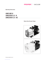
This operating manual is for customers of Pfeiffer Vacuum. It describes the func-
tioning of the designated product and provides the most important information for
safe use of the unit. The description follows applicable EU guidelines. All informa-
tion provided in this operating manual refer to the current state of the product's de-
velopment. The documentation remains valid as long as the customer does not
make any changes to the product.
Up-to-date operating instructions can also be downloaded from
www.pfeiffer-vacuum.net.
Applicable docu-
ments
*also available via www.pfeiffer-vacuum.net
1.2 Conventions
Safety instructions The safety instructions in Pfeiffer Vacuum operating manuals are the result of risk
evaluations and hazard analyses and are oriented on international certification
standards as specified by UL, CSA, ANSI Z-535, Semi-S1, ISO 3864 and DIN 4844.
In this document, the following hazard levels and information are considered:
Penta 10/20/35 Operating instructions
Safety information for vacuum pumps "Safety Guide" PT 0300 BN*
Declaration of Conformity Part of this document
Operating instructions for accessories (order-specifically) see section "accessories"*
DANGER
Immediate danger
Death or very severe injuries occur.
WARNING
Possible danger
Death or injuries may occur.
CAUTION
Possible danger
Medium to slight injuries may occur.
NOTE
Command or note
Command to perform an action or information about properties, the disregarding of
which may result in damage to the product.

4
About this manual
Pictograph
definitions
Instructions in the
text
Work instruction: here you have to do something.
Symbols used The following symbols are used consistently throughout in all illustrations:
Vacuum flange
Exhaust flange
Gas ballast valve
Power connection
Prohibition of an action or activity in connection with a
source of danger, the disregarding of which may result in
serious accidents.
Warning of a displayed source of danger in connection
with operation of the unit or equipment.
Command to perform an action or task associated with a
source of danger, the disregarding of which may result in
serious accidents.
V
G

5
Safety
2Safety
2.1 Safety precautions
• Do not expose any body parts to the vacuum.
• Observe the safety and accident prevention regulations.
• Check regularly that all safety precautions are being complied with.
• Do not carry out any unauthorised modifications or conversions to the pumps.
• Depending on the operating and ambient conditions, the surface temperature of
the pumps may rise above 70 °C. Use suitable finger guards if necessary.
• When returning the pumps to us please note the instructions in the Service sec-
tion.
2.2 Proper use
• The vacuum pump may only be used to generate a vacuum.
• Installation, operating and maintenance regulations must be complied with.
• Other accessories than those described in this manual must not be used without
the agreement of Pfeiffer Vacuum.
2.3 Improper use
Improper use will cause all claims for liability and guarantees to be forfeited. Im-
proper use is deemed to be all use for purposes deviating from those mentioned
above, especially:
• Pumping of corrosive gases.
• Pumping of explosive media.
• Operation of the pump in potentially explosive areas.
• Pumping of gases containing impurities such as particles, dusts and condensate;
note the vapour compatibility levels of the pump.
• Pumping of substances that tend to sublime.
• Use of the vacuum pump to generate pressure.
• Pumping of liquids.
• The use of operating fluids not specified by Pfeiffer Vacuum.
• Connection to pumps or units which are not suitable for this purpose according
to their operating instructions.
• Connection to units which have exposed voltage-carrying parts.
NOTE
Duty to inform
Each person involved in the installation, operation or maintenance of the vacuum
pump must read and observe the safety-related parts of these operating instructions.
Absolute observe the safety information for vacuum pumps (PT 0300 BN) !
The operator is obligated to make operating personnel aware of dangers originating
from the vacuum pump, the pumped medium and the entire system.
NOTE
CE conformity
The manufacturer's declaration of conformity becomes invalid if the operator modifies
the original product or installs additional components.
Following installation into a plant and before commissioning, the operator must
check the entire system for compliance with the valid EU directives and reassess it
accordingly.

6
Transport and storage
• The operation of the devices in potentially radioactive areas.
3 Transport and storage
3.1 Transport
Remove the locking cap from the vacuum and exhaust flange immediately be-
fore connecting!
– Check the cone strainer, paying attention to the o-ring.
Use only the eye bolt on the top side of the pump to lift the pump.
Fig. 1: Transporting the pump
3.2 Storage
Check that all the openings on the pump are securely closed.
Store the pump in a cool, dry place; preferably at room temperature (approx.
20°C).
– For a longer period of storage, seal the pump in a PE bag with drying agents
enclosed.
– For a period of storage longer than one year, it is recommended to carry out
maintenance and change the operating fluid.

7
Product description
4 Product description
4.1 Product identification
To correctly identify the product when communicating with Pfeiffer Vacuum, al-
ways have the information from the rating plate available.
• Pump model and model number
• Serial number
• Type and amount of operating fluid
• Date of manufacture
Fig. 2: Product identification on the rating plate
Scope of delivery • Pump with drive unit
• Operating fluid P3 (for standard pump)
• Cone strainer and centering ring with O-ring
• Locking cap for vacuum and exhaust flange
• Remote plug with bridge (On/Off function)
• Operating instructions
Pump types
D-35641 Asslar
Mod.: Penta 20
Mod.-Nr.: PK D74 xxx
Ser.- Nr.: 3454440
S : max. XXX m /h
Oil : P3 X l
Mass : XX kg
n : XXXX 1/min
(N )
2
3
max.
Made in Germany 2005/01
Pump type Pumping speed [m
3
/h]
Penta 10 11
Penta 20 22
Penta 35 34

8
Product description
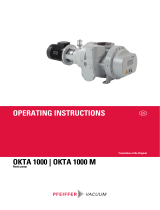
4.2 Function
The PentaLine
®
pumps are two-stage rotary shutter pumps with an electronic drive
concept for all coarse and fine vacuum applications. Since the drive is coupled to
the pump system by a contactless mechanism, it suffers no mechanical wear and
is completely maintenance-free. The pumps are equipped with a vacuum safety
valve that vacuum seals the vacuum chamber and vents the pump at the same time
when the pump is at a standstill.
Fig. 3: Penta 10/20/35
1 Vacuum flange
2 Exhaust flange
4 Casing panel
6Base
32 Mains connection
50.1 Remote connection
50.2 Remote plug with bridge
161 Gas ballast valve
162 Connection for operating fluid
return line
172 Operating fluid filler screw
172a Operating fluid drain screw
V
G
172
172a
161
161
2
1
50.1
50.2
32
4
6

9
Installation
5 Installation
5.1 Setting up the pump
Installation location When installing the pump, observe the following conditions:
• Note the load-bearing capacity of the mounting surface.
• Maximum installation altitude 1000 m (above mean sea level)
• Permissible ambient temperature: +12 ... 40°C
• Maximum relative humidity 95%
Fig. 4: Installation
Fill up with operating fluid before operating the first time (see p. 14, chap. ).
– Amount and type according to rating plate
Always place the pump on a firm, even surface.
– Where stationary installation is involved, anchor the pump on site.
When installing the pump in a closed housing, ensure there is sufficient air cir-
culation.
– Sightglass and gas ballast valve must be visible and readily accessible.
– Voltage and frequency information given on the motor rating plate must be
visible.
5.2 Connecting the vacuum side
Remove locking cap from the vacuum flange;
– pay attention to the cone strainer and the respective O-ring in the intake port.
The connection between the pump and the recipient should be kept as short as
possible.
max. 10
°
≥ 35 mm
≥ 5 mm
±
≥ 5 mm

10
Installation
– Depending on the pump type, use metallic hoses or PVC hoses with flange
connections.
– Separators, filters etc. may be installed upstream to protect the pump (see ac-
cessories). However, please observe the loss of pumping capacity due to the
conductivity of the accessories.
5.3 Connecting the exhaust side
Choose the cross-section of the exhaust line to be at least the size of the nominal
connection diameter of the vacuum pump's exhaust connection.
Piping to the pump must be suspended or supported.
– Physical forces from the piping system must not be allowed to act on vacuum
pumps.
Lay piping from the pump sloping downward so that no condensate can flow
back into the pump; otherwise fit a condensate separator.
– If an air trap is created in the system, then a device for draining condensation
water must be provided at the lowest point.
5.4 Connecting to the mains power supply
The input voltage may lie in the ranges 100 ... 120 VAC (50/60 Hz) and 200 ... 240
VAC (50/60 Hz). The pump is preset ex works to a voltage range of 200 ... 240 VAC.
In case of another supply voltage the input has to be switched over accordingly.
CAUTION
High pressure in the exhaust line!
Danger of damage to the seals and danger of the pump bursting.
Install the line without shut-off valves on the exhaust side.
If there is danger of a build-up of excess pressure (> 1500 mbar abs.) in the lines,
observe all official accident prevention safety regulations.
If the exhaust gases are being extracted, the exhaust pressure must be at least
250 mbar greater than the pressure at the intake side.
WARNING
Emission of toxic substances from the exhaust!
Danger of poisoning from emitted gases or vapours, which can be detrimental to
health and/or can pollute the environment, depending on the particular application.
Comply with the applicable regulations when working with toxic substances.
Only officially approved filter systems may be used to separate and remove these
substances.
DANGER
Voltage-bearing elements
Danger to life from electric shock.
The electrical connection can be carried out only by trained and authorised electrici-
ans.
Ensure the system is adequately earthed.

11
Installation
Connecting to the
mains power supply
Permissible input voltage range:
• 100 ... 120 VAC ( ± 10 %)
• 200 ... 240 VAC ( ± 10 %)
Fig. 5: Power supply pin assignment; Type: Harting Han 3A
The drive electronics ensures automatically the correct direction of rotation of the
pump.
Fuse protection
To protect the motor in case of malfunction, carry out fuse protection in accor-
dance with the regional regulations.
– Select a fuse with slow characteristics.
WARNING
Safe electrical installation
Safe operation after installation is the responsibility of the operator. The pump and its
electrical equipment have no lock-out/tag-out device and no emergency off device.
Make sure that the system is integrated in an emergency off safety circuit.
– If an emergency off situation is triggered, the voltage supply must be imme-
diately interrupted.
Consult Pfeiffer Vacuum for special requirements.
CAUTION
Excess voltage!
Danger of destroying the motor.
Power connections must comply with local regulations. Voltage and frequency infor-
mation given on the motor rating plate must correspond to the mains voltage and
frequency values.
To protect the motor and supply cable in case of malfunction, mains fuse protection
must be implemented.
1 Neutral conductor
2 Phase L1
3 not connected
4earth, PE
1
23
4

12
Installation
Fig. 6: Example for fuse protection for single phase operation
max. current: 17.7 A
Changing the voltage
range
The mains voltage must be determined on-site each time before the pump is in-
stalled or moved to a different location.
A voltage selector switch below the connector plate enables toggling between the
two voltage ranges. The factory default setting is 200 ... 240 VAC.
Fig. 7: Changing the voltage range for the power supply
Disconnect the pump from the power supply.
L1
N
PE
02 04 01
F 1
NOTE
Overvoltage!
An incorrect voltage range setting can damage the motor.
Disconnect the pump from the power supply.
Only change the voltage range when the pump is disconnected from the power
mains.
S Voltage selector switch
240
240
120
S

13
Installation
Remove the connector plate and set the voltage selector switch "S" to the desi-
red voltage range.
Monitoring of the
operation conditions
The pump features the following functions for monitoring the pump components:
• Monitoring the temperature of the electronics
– Resetting by briefly removing the remote connector or by disconnecting from
the mains ("Off/On").
• Monitoring the internal motor winding temperature
– Resetting by briefly removing the remote connector or by disconnecting from
the mains ("Off/On"), followed by pump cooling.
• Surge current shut-down of electronics
– Resetting by briefly removing the remote connector or by disconnecting from
the mains ("Off/On").
5.5 Make remote connection
Fig. 8: Remote connector pin assignment M12 socket, 4-pin (A-coded)
2+ 24 V*
2-1 Pump "On"
2-3 Temperature control mode "On"
2-4 Standby "On"
1
2 (+24 V)
1
3
4
2
34

14
Installation
5.6 Filling up the operating fluid
The type and amount of operating fluid should be visible on the pump's rating
plate for every rotary vane pump.
The delivery consignment for the standard pump contains sufficient operating
fluid for one filling. The use of other operating fluids requires prior authorisation
from Pfeiffer Vacuum.
Permissible operating fluid
• P3 (standard operating fluid)
• Operating fluid for special applications on request
Filling up the opera-
ting fluid
Unscrew operating fluid filler screw 172.
Fill up operating fluid.
– Correct filling level during operations: Within the markings at the sightglass
frame.
Fig. 9: Filling up the operating fluid
Screw in operating fluid filler screw 172.
Check operating fluid level only when the pump is warm and running; close
– vacuum flange and gas ballast valve to do so,
– Check operating fluid daily in non-stop operation, otherwise whenever the
pump is switched on. Refilling is possible when the pump is in final vacuum
operation.
NOTE
Guarantees relating to attainment of final pressures and trouble free functioning
of the pump apply only providing a permissible operating fluid is used.
max.
min.

15
Installation
5.7 Operations monitoring (Option)
A pressure switch can be installed on the side of the support to monitor the oper-
ating fluid pressure of the rotary vane pump during operations. By pressure drop
and when the pump is at rest, the contact of the pressure switch opens. The signal
can be used to control external valves.
Fig. 10: Pressure switch; installation location and circuit diagram
5.8 Fitting the ONF and the oil return line (option)
For frequent pumping at higher intake pressures the use of an oil mist filter with
oil return line is recommended in order to reduce the discharge of oil mist.
Fig. 11: Penta 35 with oil mist filter ONF 25 XL
Switching voltage: 5 ... 250 Volt (potential-free)
Current, max. 2 Amp.
Protection class IP 55
1 + 2 closers = pressureless open
1
2
243
242
33
(241/145)
77
(78)

16
Operation
Position the ONF on the small flange on the exhaust side of the pump and fit
using the tension ring (accessory); take care with the centering ring.
Screw in hose nipple 241 inplace of the operating fluid drain screw.
Fit operating fluid return hose 242 at both sides on the hose nipples and tighten
with hose clip at the ONF side.
6 Operation
6.1 Before switching on the pump
Check the operating fluid level in the sightglass.
Compare the voltage and frequency information on the rating plate with the
mains voltage and frequency values.
Check that the exhaust connection allows free flow (max. permissible pressure
1.5 bar absolute).
– Activate the shut-off valves in such a way that they open before or at the same
time as the pump is started.
Protect the pump sufficiently from taking in contaminants by means of suitable
precautions (e.g. dust filters); if necessary, check operating fluid regularly or re-
place at shorter intervals.
6.2 Switching on the pump
The pump can be switched on in any pressure range.
No special precautions are necessary when pumping dry gases. In order to attain
the lowest possible final pressures, the gas ballast valve should be closed.
Switch-on pump via remote plug with bridge 50.2.
Standby The pump can be operated with reduced rotation speed (standby) during process
breaks or in cases with small load. Thus the power consumtion of the pump is re-
duced and the operating temperature of the pump lowered.
Bridge Pin 2 and Pin 4 at remote connection 50.1 (see p. 13, chap. 5.5);
– use customized remote plug (see p. 27, chap. 12).
CAUTION
Hot surface!
Danger of burns if hot parts are touched. Depending on the operating and ambient
conditions, the surface temperature of the pump may rise above 70 °C.
In this case, use suitable finger guards.
NOTE
Improper operating status of the pump!
Simultaneously standby and temperature control mode leads to an increased opera-
ting temperature and therefore to switching off the pump.
In addition, do not use gas ballast while the pump is on standby.

17
Operation
6.3 Pumping condensable vapours
Should the process gases contain condensable gases present at high percentages,
the rotary vane pump must be operated with a gas ballast (i.e. with an open gas
ballast valve).
Gas ballast valve,
standard version
To avoid condensation in the pump when pumping condensable vapours, air is pe-
riodically fed into the working chamber at the beginning of the compression phase
via the gas ballast valve 161.
Open gas ballast valve; to do so, turn cap 43 on the gas ballast valve 161 so that
the two holes line up.
Fig. 12: Operation with gas ballast valve 161
Temperature control
mode
Operating the pump in temperature control mode will further improve the dis-
charge of liquids when pumping large volumes of condensable vapours. The fan
is temporarily switched off to increase the operating temperature of the pump.
Open gas ballast valve; to do so, turn cap 43 on the gas ballast valve 161 so that
the two holes line up.
Bridge Pin 2 and Pin 3 at remote connection 50.1 to switch on the temperature
control mode;
– use customized remote plug (see p. 27, chap. 12).
CAUTION
Bad final vacuum and damage to the pump!
Danger of condensation and corrosion due to exceeding the water vapour compatibi-
lity (see Technical data) during operation without a gas ballast or in case of insufficient
supply of flushing gas.
Only pump vapours when the pump is warm and the gas ballast valve is open.
When the process has been completed, allow the pump to continue running for
about 30 minutes with the vacuum flange closed and the gas ballast open for ope-
rating fluid regeneration purposes.
161

18
Operation
6.4 Switching off
The pump can be switched off in any pressure range.
Rotary vane pumps have an integrated safety valve on the intake side. If the differ-
ential pressure between the exhaust side and the intake side is ≥ 250 mbar, then
the valve closes automatically and vents the pump when the pump is switched off.
Switch-off pump by disconnecting from mains or via remote bypass50.2.
Venting the vacuum
chamber
Maintaining the va-
cuum in the chamber
CAUTION
Danger of backflow of operating fluid into the intake line!
Contamination of the connected vacuum system!
Vent the vacuum chamber within 30 s, regardless of the chamber size.
For a longer venting process, use an additional shut-off valve and shut off the intake
line after switching off the pump.
CAUTION
Danger of backflow of operating fluid into the intake line!
Contamination of the connected vacuum system!
Because the safety valve of the pump is not suitable for longer-term sealing, install
an additional shut-off valve in the intake line.
Shut off the intake line immediately after switching off the pump.

19
Maintenance
7 Maintenance
7.1 Precautions
Switch off the pump, vent it to atmospheric pressure and let it cool down.
Disconnect the drive motor from the mains and secure it so that it cannot be
switched on.
Only dismantle the pump as far as necessary in order to repair defects.
Dispose of used operating fluid in compliance with local regulations.
When using synthetic operating fluids or working with toxic substances or sub-
stances contaminated with corrosive gases, the relevant instructions governing
their use must be observed.
Use only alcohol or similar agents for cleaning pump parts.
Checklist for inspec-
tion, maintenance
and overhaul
Certain repair and overhaul work should only be performed by Pfeiffer Vacuum
Service (PV). Pfeiffer Vacuum will be released from all warranty and liability claims
if the required intervals for inspection, maintenance, or overhaul are exceeded or
inspection, maintenance, repair or overhaul procedures are not performed proper-
ly. This also applies if replacement parts other than Pfeiffer Vacuum OEM replace-
ment parts are used.
WARNING
Pump parts may be contaminated from pumped media!
Danger of poisoning due to contact with harmful substances.
Decontaminate the pump before carrying out any maintenance work.
In the event of contamination, take suitable safety precautions to prevent your health
from being harmed by any dangerous substances.
Activity daily as required;
at least
annually
as required;
at least
every 2
years
as required;
at least
every 4
years
Check operating fluid level X
Visual inspection (leak-tightness/oil
leaks)
X
Check filter insert of external oil mist filter
(if existent)
X
Change filter insert of external oil mist fil-
ter (if existent)
X
Change operating fluid X
Cleaning the pump and renew the seals X
Clean gas ballast valve and silencer
nozzle
X
Clean the fan intake side X
Clean or change vacuum safety valve X (PV)
Clean or change exhaust valves X (PV)
Change vanes and hydraulic vane X (PV)
Depending on the process, the required replacement intervals for lubricants and the intervals for
inspection, maintenance and overhaul may be shorter than the guide values specified in the table.
Consult with Pfeiffer Vacuum Service if necessary.

20
Maintenance
7.2 Changing the operating fluid
The changing interval for the operating fluid depends on the pump applications,
but should be carried out once a year.
Switch off pump.
Unscrew operating fluid drain screw 172a and drain operating fluid.
Fill the specimen in a test tube or some similar vessel and test by holding
against the light.
The level of deterioration of operating fluid P3 can be read off the colour scale
in accordance with DIN 51578; request the supplementary sheet PK 0219 BN or
download it from the Internet.
Where discolouration is dark yellow to red brown (equivalent to 4 ... 5 on the sca-
le) change operating fluid.
Fig. 13: Draining the operating fluid
NOTE
Depending on the applications, Pfeiffer Vacuum recommends determining the
exact service life of the operating fluid during the first year of operation.
The replacement interval may vary from the guide value specified by Pfeiffer Vacuum
depending on the thermal and chemical loads, and the accumulation of suspended par-
ticles and condensation in the operating fluid.
WARNING
Hot operating fluid!
Danger of burns when draining due to contact with skin.
Wear suitable protective clothing.
Use a suitable collecting vessel.
172a
/