Proxima Ultralight SV1 User manual
- Category
- Data projectors
- Type
- User manual

Technical Support Proxima ASA
Horsterweg 24, 6191 RX, Beek, The Netherlands
Tel: +31 43 358 5210 Fax: +31 43 358 5202
Ultralight SV1
MODULE LEVEL SERVICE MANUAL

MODULE LEVEL Ultralight SV1 101.670
SERVICE MANUAL
Proxima ASA CONFIDENTIAL2
1 TABLE OF CONTENTS
1 TABLE OF CONTENTS.........................................................................................................................2
2 REVISION HISTORY .............................................................................................................................2
3 SCOPE...................................................................................................................................................3
4 MODULE LEVEL SERVICE AGREEMENT ...........................................................................................3
5 ASSOCIATED DOCUMENTATION .......................................................................................................3
6 REPLACEMENT OF MODULE LEVEL ELEMENTS .............................................................................4
6.1 SAFETY GUIDELINES....................................................................................................................4
6.2 PROTECTIVE CLOTHING..............................................................................................................4
6.3 TOOLS............................................................................................................................................4
7 TROUBLESHOOTING...........................................................................................................................5
7.1 WORK PROCEDURES...................................................................................................................8
7.1.1 GENERAL PROCEDURES .....................................................................................................8
7.1.2 REPLACEMENT OF MECHANICAL AND ELECTRONIC PARTS .........................................9
8 WIRING CONNECTION DIAGRAM, TOP AND BOTTOM CABINET .................................................12
2 REVISION HISTORY
18.03.99 HM Draft of Module level service Manual for SVGA LCD PROJECTOR
08.06.99 HM Draft with referance to new SPP-structure
21.06.99 HM Release of revision A
17.08.99 HM Release of revision B
18.08.99 HM Release of revision C

MODULE LEVEL Ultralight SV1 101.670
SERVICE MANUAL
Proxima ASA CONFIDENTIAL3
3 SCOPE
This document describes the assembly of the SVGA LCD Projector unit at module level detail, and serves as
a guide for the replacement of such elements when the unit needs servicing. The document does not assist
in repairing the elements themselves (such as replacing individual components on the electronic circuit
boards).
The information contained in this document may be subject to change without prior notice.
4 MODULE LEVEL SERVICE AGREEMENT
Only the primary customer named in the Module level service Agreement may carry out the repairs detailed in
this document.
Any unauthorised repair that is performed outside the scope of this document will violate
any warranties and could potentially damage the unit.
5 ASSOCIATED DOCUMENTATION
For Sparepart & Accessory overview, please refer to the ASK web-page.

MODULE LEVEL Ultralight SV1 101.670
SERVICE MANUAL
Proxima ASA CONFIDENTIAL4
6 REPLACEMENT OF MODULE LEVEL ELEMENTS
The following procedures must only be carried out by qualified and experienced service
personnel authorized by means of the Module Level Service Agreement to perform module
level repairs on LCD projector units.
Always remember to test the product thoroughly immediately after service.
6.1 SAFETY GUIDELINES
The following safety guidelines should be followed at all times. Failure to do so could seriously damage the
projector unit, or create a hazard to the service personnel or projector unit owner, and may violate warranties
on the product.
This product operates on mains voltage. Make sure to unplug the power cord before
attempting to open the unit. To avoid burns, do not open the unit to replace parts until it has
cooled down completely after use. The interior of the projector becomes hot during operation.
Do not under any circumstances operate the lamp whilst the housing is open, as there is a risk
of permanent injury due to contact with high voltage elements, explosion of the glass lamp
bulb or exposure to high levels of UV radiation.
The UHP-lamp used is high voltage when starting and high-pressure when operating.
6.2 PROTECTIVE CLOTHING
The following protective clothing should be worn in addition to normal work clothing when servicing the unit:
• Static free cotton gloves
• Full face visor (for all replacements of illumination/optical module level elements)
6.3 TOOLS
The work should be performed at a static-free workstation. Work in a dust-free environment if possible and
have access to a high-pressure air blower to remove dust when assembling the unit.
The following tools are required to service the LCD projector unit:
ID TOOL USED FOR
1 Torx no. 10 screwdriver Replacing elements
2 Torx no. 8 screwdriver Replacing elements (e.g. main fan(s))
3 Pair of snipe-nosed pliers Miscellaneous (e.g. removing cables/springs)

MODULE LEVEL Ultralight SV1 101.670
SERVICE MANUAL
Proxima ASA CONFIDENTIAL5
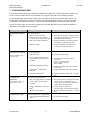
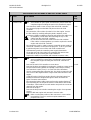
7 TROUBLESHOOTING
This troubleshooting guide helps determining what parts to replace if a defective projector comes in for
service. Not all possible defects are described here, only the ones that are most likely to appear.
For replacement procedures, please refer to the Servicing the Unit-section following this section. For
pricing details of the various parts, please refer to the Sparepart and Accessories Pricelist-document
on the web. The numbers in brackets ( ) refer to the exploded drawing of the module level elements.
Please also refer to the User Guide for setting up the unit with different sources and other additional
information not available in this document.
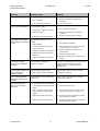
PROBLEM PROBABLE CAUSE REMEDY
White image projected
only
Loss of image data
1. Bad flex cable connection
between main PCB controller
connector and Polysilicone engine
2. Main PCB
controller defective
3. Defective engine
1. Reconnect flex cable connectors (3 pcs)
(See “Work Procedures” in section 7.1.2
task “Main PCB Controller”)
2. Replace defective main PCB controller
and engine (considered one part)
3. Replace defective engine and PCB
controller (considered one part)
Lamp does not start up
(LEDs are lighted on top
panel, fans run)
Loss of lamp power
1. Defective lamp
2. Loss of enable signal to lamp
power supply
(6)
from main PCB
controller
3. Defective main PCB controller
4. Lamp power
(6)
(ballast unit)
defective
5. Defective mains filter
(4)
1. Replace defective lamp
2. Reconnect/secure loose enable
connector
(Green ~ 0.2V/5V, on/off
Red ~ 4V/0.1V, on/off
Black: GND)
3. Replace defective main PCB controller
and engine
4. Replace defective lamp power supply
5. Replace defective mains filter (~ + 400V
DC)
Complete unit
inoperative
(all operations inactive, no
light, no LED, no fan)
No power to internal functions
1. Bad connection between controller
power supply
(5)
to main PCB
controller
2. Broken mains fuse (F1 at mains
filter
(4)
)
3.
Defective mains filter
(4)
1. Reconnect 6 pin PC-edge connector (DC
voltage to main PCB: GND 5V, 6V,
15.3V, 16.5V, 5V, 3.3V seen from front
GND towards projection lens)
2. Replace broken mains fuse
(Schurter Type: SP 2.5A Fast 250 VAC)
3. Replace defective mains filter (~ + 400V
DC)
Garbled video image
Loss of image synch or image data
1. User programmable parameters
illegal
1. Execute Factory Reset

MODULE LEVEL Ultralight SV1 101.670
SERVICE MANUAL
Proxima ASA CONFIDENTIAL6
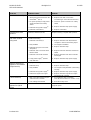
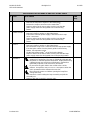
PROBLEM PROBABLE CAUSE REMEDY
Excessive fan noise
Main fan(s) defective
1. Fan
(3)
defective
2. Fan mount out of position
1. Replace defective fan(s)/fanhouse
complete
2. Secure fan mount
Fan(s) is/are inoperative
Loss of power to fan(s)
1. Loose fan(s)
(3)
wiring connector
2. Defective fan(s)
(3)
3. Defective main PCB controller
1. Reconnect/secure wiring
2. Replace defective fan(s)/fanhouse
complete
3. Replace defective PCB controller
Dark spot in the middle
of the image, increasing
in size
Overheating of Polysilicone LCD
module
1. Dirty dustfilter
2. Loose Polysilicone engine fan
power connector
3. Defective Polysilicone engine fan
4. Defective lamp (too much heat
radiation)
5. Defective main PCB controller
1. Clean/replace dustfilter
2. Reconnect/secure loose Polysilicone
engine fan power connector
3. Return engine fan to producer for
replacement
4. Replace defective lamp
5. Replace defective PCB controller and
engine
Red, green or blue
colours are misaligned
in image
LCD modules misaligned in
Polysilicone engine
Centre of coinciding pixels may be up to 1,5
pixels’ width apart (gap of 0.5 pixels
between). This is still inside optical
specification
Line of pixels in different
color crossing the
image (hor/vert)
Defective line of pixels in LCD
module of the Polysilicone engine
Entire engine and main PCB controller
needs to be replaced
Parts of the projected
image are discoloured
or white
Defective field in LCD module of the
Polysilicone
Entire engine and main PCB controller
needs to be replaced
Image projected as
vertical or horizontal
lines only
Loss of image synch or image data
1. User programmable parameters
illegal
2. Bad connection between main
PCB controller controller
and
engine
3. Defective Polysilicone engine
4. Defective main PCB controller
1. Execute Factory Reset
2. Reconnect flex cable connector (See
“Work Procedures” in section 7.1.2)
3. Replace defective Polysilicone engine
and main PCB controller
4. Replace defective main PCB controller
and Polysilicone engine

MODULE LEVEL Ultralight SV1 101.670
SERVICE MANUAL
Proxima ASA CONFIDENTIAL7
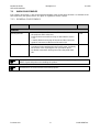
PROBLEM PROBABLE CAUSE REMEDY
Fuse breaks instantly
Too much current to the unit
1. Wrong fuse value inserted on the
mains filter
(4)
(at F1)
2. DC power polarity to lamp power
supply inverted at the safety
switch
3. Defective lamp power supply
(6)
4. Defective mains filter
(4)
1. Replace fuse with correct value
(Schurter Type: SP 2.5A Fast 250 VAC)
2. Check DC power connection on safety
switch
3. Replace defective lamp power supply
4. Replace mains filter
Distorted noise from
speakers
Speaker(s)
defective (blown) Replace housing complete with speakers
Unit shuts off while
being used
Possible overheating
1. Defective main fan(s)
(3)
2. Dirty dustfilter
3. Defective lamp (too much heat
dissipation)
4. Defective 100°Celcius Bi-metal
thermo switch
5. Defective main PCB controller
6. Lamp power supply
(6)
(ballast
unit) defective
1. Replace defective main fan/fanhouse
complete or remove obstructing object
2. Clean/replace dustfilter
3. Replace defective lamp
4. Replace fanhouse with fans and thermo
switch
5. Replace defective main PCB controller
and engine
6. Replace defective lamp power supply
Image is flickering or
appears to be unstable
in light intensity
Lamp light is flickering
1. Defective lamp
2. Dirty dustfilter
3. Defective lamp power supply
(6)
4. Defective Polysilicone engine
1. Replace defective lamp
2. Clean/replace dirty dustfilter (overheating
of lamp)
3. Replace defective lamp power supply
4. Replace defective Polysilicone engine
and main PCB controller
Colours break up
1. Bad connection between engine
and main PCB controller
2. User settings not allowed
1. Secure/fix flex cable connection
(See “Work Procedures” in section 7.1.2)
2. Execute Factory reset
White vertical line
appears far right in
picture
Synchronization error Perform RESET on remote control or
projector panel

MODULE LEVEL Ultralight SV1 101.670
SERVICE MANUAL
Proxima ASA CONFIDENTIAL8
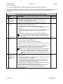
7.1 WORK PROCEDURES
The numbers in brackets ( ) refer to the exploded drawing of the module level elements. An estimate of the
time required for the replacement is also given as a guide for service charges.
7.1.1 GENERAL PROCEDURES
TASK PROCEDURE TIME REQ.
GENERAL
Opening the unit
• Unscrew the 8 pcs cabinet screws, 7 located on the sides of
the projector and 1 at the rear.
• Remove the zoom and focus rings as described in section
7.1.2.
• Carefully lift the housing top off the unit and disconnect the
speaker connectors at the front of the main PCB.
5 min.
Reassembling the unit
• This is assumed to be the necessary stages of any of the
procedures below performed in the reverse order, and finally
the reverse of the “Opening the unit” procedure above.
• No further instructions will be given unless they differ from
this.
5 min.
Always remember to make a note of the cable connections when performing service, as this
will be of great help when reassembling the product.
All references are seen from the front of the projector.

MODULE LEVEL Ultralight SV1 101.670
SERVICE MANUAL
Proxima ASA CONFIDENTIAL9
7.1.2 REPLACEMENT OF MECHANICAL AND ELECTRONIC PARTS
All replacement operations require that the unit is opened; an open unit is therefore assumed in the following
replacement procedures. The numbers in the left column and in the text refers to the exploded view
illustration.
REPLACEMENT OF MECHANICAL AND ELECTRONIC PARTS
# TASK PROCEDURE TIME REQ.
1 HOUSING
BOTTOM
(part of Housing
Complete)
• Remove the main PCB controller, Polysilicon engine, rear cover,
housing handle,
adjustable feet,
and dust cover with filter,
as
described in their respective sections.
• Replace the housing bottom
(1)
and remount in reverse order.
30 min.
2 PROJECTION
LENS
• Remove the main PCB controller and Polysilicon engine
as
described in their respective sections.
• Remove the zoom and focus rings as described below.
• Unscrew the 4 cross-slot screws holding the projection lens
(2)
to the
engine.
• Replace with new lens, making sure that the 2 plastic guides on the
lens enters their designated holes on the engine. Fasten the
screws.
• Remount the zoom/focus rings and reassemble the projector.
20 min.
Do not touch the optics; prism in engine or lens glass, as this
may severly reduce the optical quality or damage the engine
permanently.
ZOOM & FOCUS
RINGS
• Take hold of the focus ring
between your thumb and index finger.
• Apply pressure and pull/wriggle the ring off the projector lens. If this
is not sucessful, try moving your grip.
• Remove the housing top as described previously.
• To remove the zoom lens, turn the rear end of the projector towards
you.
• Place your thumbs behind the zoom ring on each side of the lens
and apply pressure outwards, until the ring slides off the lens.
• Replace with new rings and remount in reverse order.
2 min.
Make sure to enter the focus ring retainers onto the drilled pits
in the lens assembly rim groove. The zoom ring has 3 holes
which should be fitted onto the screw heads on the lens assy
and it is correctly fitted when you hear a clicking sound when
mounting.
3 FANHOUSE
COMPLETE
(w/ cooling fans
and thermo
switch)
• Remove the main PCB controller and the Polysilicon engine as
seen above.
• Remove the fanhouse
(3)
by unscrewing the 2 screws at the top and
1 screw at the bottom of the engine.
• Hold the engine in a firm grip with the lens pointing towards you,
your left hand supporting the rear left corner and your right hand
enclosing the rear right corner of the fanhouse.
• Bend the fanhouse carefully down sideways, releasing the 2 upper
plastic retainers and pull it away from the engine.
• Replace and remount in reverse order by snapping the fanhouse
onto the engine. Make sure that the retainers enters their
designated holes.
15 min.

MODULE LEVEL Ultralight SV1 101.670
SERVICE MANUAL
Proxima ASA CONFIDENTIAL10
REPLACEMENT OF MECHANICAL AND ELECTRONIC PARTS
# TASK PROCEDURE TIME
REQ.
MAIN PCB
CONTROLLER
Neither the Polysilicone engine nor the main PCB controller
are available as spare parts. If malfunction, please return the
complete engine including the main PCB controller for repair .
• Unscrew the 4 metal screws on top of the main PCB controller.
• Disconnect all plugs marked with silk print on the main PCB
controller.
• Disconnect the 3 flex cables from the PCB
to the engine. Loosen
the flex cables by carefully pulling the plastic retainers on the
connectors slightly out without removing and pull the flex cables out.
5 min
Be extremely careful when disconnecting the 3 pcs. flex
cables from the main PCB controller!
Do not disconnect the flex cables from the LCD modules!
If flex cables are damaged/torn you need to replace the entire
engine and main PCB controller.
• Disconnect the 6 pin PC-edge connector (controller power supply to
main PCB controller) on the left of the projector. To do so you need
to pull the adjacent corner of the main PCB controller and
simultaneously push the controller power supply downwards.
• Lift up the rear end of the main PCB controller and remove rear
cover
with fan by unscrewing the single nutwasher.
• Replace the main PCB controller and remount in reverse order.
POLYSILICONE
ENGINE
Neither the Polysilicone engine nor the main PCB controller
are not available as spare parts. If malfunction, please return
the complete engine including the main PCB controller for
repair.
• Remove the main PCB controller as seen above.
• Remove the lamp assembly
by loosening the 3 retainer screws on the
lamp lid at the housing bottom and pulling out the lamp assembly.
• Unscrew the 4 screws (Torx), 1 on each side of the aluminum
chassis sourrounding the projection lens, the single screw on the left
rear corner of the engine and the single screw at the left side of the
engine.
• Gently lift up the Polysilicone engine from the housing bottom in a
twisting movement to lenghten the ignitor cables and ease the
ignitor connector removement.
• Disconnect the ignitor cable connector from the engines fanhouse
(2)
by first bending one of the plastic retainers aside with a flat headed
screwdriver. Then bend the second retainer and push the connector
upwards from the engine.
• Remove the engine.
• Remove the lamp house before returning the engine. See separate
section.
• Replace with new engine and remount in reverse order.
10 min.
Make sure that the position of the connector is correct when
reassembled. The no 1 mark must point towards the
projection lens end.

MODULE LEVEL Ultralight SV1 101.670
SERVICE MANUAL
Proxima ASA CONFIDENTIAL11
REPLACEMENT OF MECHANICAL AND ELECTRONIC PARTS
# TASK PROCEDURE TIME
REQ.
4 MAINS FILTER
• Remove main PCB controller as described above.
• Remove the Polysilicon engine as described above.
• Release the snapon connector on the mains filter
(4)
.
• Replace and mount in reverse order, making sure that the
power supply enters the designated slots in the housing
bottom.
5 min.
5 CONTROLLER
POWER SUPPLY
• Remove main PCB controller as described above.
• Remove Polysilicon engine as described above.
• Pull out the controller power supply
(5)
and release the 2 snap
on DC connectors.
• Replace and mount in reverse order, making sure that the
power supply enters the designated slots in the housing
bottom.
15 min.
6 LAMP POWER
SUPPLY
• Remove main PCB controller as described above.
• Remove Polysilicon engine as described above.
• Disconnect the snap-on DC connector from the lamp power supply.
• Free the ignitor cables from the plastic guides in the housing
bottom. See separate section.
• Lift the lamp power supply
(6)
out of the housing bottom.
• Replace and mount in reverse order, making sure that the lamp
power supply enters the designated slots in the housing bottom.
15 min.
LAMP
ASSEMBLY
Use only original lamp and holder as specified in the user
guide/service web-page. The lamp is individually adjusted with
the holder to maintain optimum illumination. Replacement using
a different lamp may result in poor illumination, malfunction
(potentially explosion) and will void any warranties
2 min.
Do not touch the glass bulb or the coated surface of the
reflector. An explosion may occur as a consequence when the
unit is operated and the elements become hot.
Disconnect the power cord before opening the lamp lid to
change the lamp.
• Unscrew the 3 screws holding the lamp assembly and pull the
assembly out.
• Replace with new assembly in reverse order.

MODULE LEVEL Ultralight SV1 101.670
SERVICE MANUAL
Proxima ASA CONFIDENTIAL12
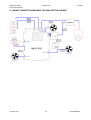
8 WIRING CONNECTION DIAGRAM, TOP AND BOTTOM CABINET
-
 1
1
-
 2
2
-
 3
3
-
 4
4
-
 5
5
-
 6
6
-
 7
7
-
 8
8
-
 9
9
-
 10
10
-
 11
11
-
 12
12


Proxima Ultralight SV1 User manual
- Category
- Data projectors
- Type
- User manual
Ask a question and I''ll find the answer in the document
Finding information in a document is now easier with AI
Related papers
-
Infocus DP8000 User manual
-
Proxima DP8500x Installation And Integration
-
 Proxima Proxima UltraLight LX2 User manual
-
Ask Proxima Pro AV 9300 User manual
-
 Proxima DESKTOP PROJECTOR 6105XGA User manual
-
-
-
-
 Proxima DESKTOP PROJECTOR 6150 User manual
-
 Proxima 6150/6100 User manual


